EP0062711A1 - Zusammensetzbare Schubladen - Google Patents
Zusammensetzbare Schubladen Download PDFInfo
- Publication number
- EP0062711A1 EP0062711A1 EP81301555A EP81301555A EP0062711A1 EP 0062711 A1 EP0062711 A1 EP 0062711A1 EP 81301555 A EP81301555 A EP 81301555A EP 81301555 A EP81301555 A EP 81301555A EP 0062711 A1 EP0062711 A1 EP 0062711A1
- Authority
- EP
- European Patent Office
- Prior art keywords
- drawers
- drawer
- aperture
- bottom panel
- support structure
- Prior art date
- Legal status (The legal status is an assumption and is not a legal conclusion. Google has not performed a legal analysis and makes no representation as to the accuracy of the status listed.)
- Granted
Links
- 230000000694 effects Effects 0.000 claims description 3
- 230000000717 retained effect Effects 0.000 claims 2
- 238000013459 approach Methods 0.000 description 4
- 210000000038 chest Anatomy 0.000 description 4
- 238000000034 method Methods 0.000 description 3
- 238000010276 construction Methods 0.000 description 1
- 238000003780 insertion Methods 0.000 description 1
- 230000037431 insertion Effects 0.000 description 1
- 239000000463 material Substances 0.000 description 1
- 239000002184 metal Substances 0.000 description 1
- 238000012986 modification Methods 0.000 description 1
- 230000004048 modification Effects 0.000 description 1
- 239000002023 wood Substances 0.000 description 1
Images
Classifications
-
- A—HUMAN NECESSITIES
- A47—FURNITURE; DOMESTIC ARTICLES OR APPLIANCES; COFFEE MILLS; SPICE MILLS; SUCTION CLEANERS IN GENERAL
- A47B—TABLES; DESKS; OFFICE FURNITURE; CABINETS; DRAWERS; GENERAL DETAILS OF FURNITURE
- A47B88/00—Drawers for tables, cabinets or like furniture; Guides for drawers
- A47B88/70—Coupled drawers
Definitions
- This invention relates to sliding drawers of the type usually held in relative vertical registration to one another in desks, bureaus and the like, and particularly to drawers which can be operably joined to one another to create one deep drawer from two or more shallow drawers.
- Drawers are a well-travelled art. Typically in the form of sliding, rectangular, box-like structures, they are slidably held in desks, bureaus, credenzas, chests of drawers, and the like in relative vertical registered alignment.
- One common characteristic drawers generally share is that once they are made, their overall dimensions, particularly their capacity for holding objects, is not easily alterable. This characteristic is unfortunate, for often, with the passage of time, requirements or needs change. For example, when one purchases a desk, the purchaser may have, at that time, required only one deep drawer and one or more shallow drawers. Susequent to the desk's purchase, the requirement may have changed to more deeper drawers and fewer shallow drawers. The approach to this problem has heretofore generally been threefold: (1) Make do with the desk as is, (2) modify the desk's structure, or (3) buy a new desk that meets these new requirements.
- a chest of drawers for example, containing a small number of vertically registered, high-capacity (i.e., deep) drawers may have been purchased with specific requirements or a particular use in mind. Yet, as time goes by, it is often found that new requirements or additional uses call for a greater number of lower- capacity (i.e., shallow) drawers. In such a case, one is once again left with the three above-stated approaches.
- the present invention provides a fourth approach to these long-endured problems, an approach that is inexpensive, practical and easy to implement.
- the invention provides structure that allows two or more separate, registered drawers to be joined in vertical alignment so that they operate as a single, large drawer.
- At least two drawers are slidably held in a support structure - a desk, for example.
- Each drawer includes an article-receiving enclosure formed from a surrounding sidewall structure having front, side and back panels.
- a bottom panel of'at least the superposed one of two drawers is removably supported within the sidewall structure, proximate one periphery thereof, by a sill that is attached to each side panel.
- the apparatus for attaching one drawer to an immediately underlying drawer is as Eollows: Affixed to at least each rear corner of the lower drawer, and adjacent the upper periphery, is a corner block having formed therein a vertically oriented aperture therethrough.
- the rear portion of each sill of the lower drawer is provided with a vertical aperture situated so that the aperture can be placed coaxial with that of the corresponding corner block of the underlying 3rawer when the two drawers are placed in vertically registered relation.
- An attachment pin is provided, configured and of a length to be easily received by and extend between the two coaxially aligned apertures formed in the sills and corner blocks of two vertically registered drawers, to join the drawers together.
- two or more drawers of the present invention are conventionally mounted in such support structure as desks, credenzas, bureaus or the like.
- the bottom panel can then be removed from the upper of the two drawers and the attachment pins inserted through the sill apertures of the upper drawer and into the underlying apertures in the corner blocks of the underlying drawer.
- the two drawers With the pins so inserted, and the bottom panel removed from the upper drawer, the two drawers are operatively joined to form a single drawer having a combined holding capacity of the two drawers.
- three or more drawers can be joined to form a single drawer of even greater holding capacity.
- An object of the invention is to provide a vertically registered grouping of drawers the ability to have two or more drawers combined into one deeper drawer or be used as separate, relatively shallow drawers. This provides the owner with the ability to tailor the size of the drawers to meet changing needs and requirements. If a deep file drawer is no longer needed, the drawers may be separated, the bottoms reinserted, and the owner quickly has the needed shallow drawers. Likewise, a chest of drawers for clothes may be converted from shallow drawers for baby clothes to deeper drawers for sweaters and other bulky clothin Another advantage accrues from the reduced costs which result. The manufacturer needs to make fewer different-sized drawers and the wholesaler and retailer need to stock fewer types of units.
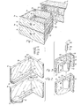
- drawers A and B constructed in accordance with the present invention and, as illustrated in Fig. 1, slidably held in a support structure C (e.g., a desk).
- the drawers A and B are identically structured and, therefore, only drawer A will be described. It will be understood, however, that the description of the parts and numbering of drawer A will apply equally to the structure and parts of the drawer B.
- drawer A includes a front or face panel 4, a back panel 6 and two spaced, parallel side panels 8 extending between the front and back panels 4 and 6, respectively, forming the familiar rectangular drawer sidewall structure.
- a planar bottom panel 10 is configured to be removably received and held within the drawer A, supported therein by a pair of spaced, parallel sills 12 that are attached to and run along the bottom peripheries of the side panels 8. As can be more particularly seen in Fig. 2, the sills 12 present an upper surface 13 for supporting the bottom panel 1 0 when inserted in the drawer A.
- a triangularly shaped corner block 18 Formed in each corner block 18 is a vertically oriented through-hole 20. A similarly dimensioned through-hole 22 is formed in each sill 12. The through hole 22 is located so as to be substantially coaxial with the overlying through-hole 20 in the corner block 18 when the two drawers A and B are situated in vertically registered alignment as illustrated in Fig. 1.
- a lock pin 24 is provided having an elongate, cylindrically shaped shaft 26, a disc-like head 28 affixed at one end of the shaft 26.
- the opposing end 30 is provided with a frustoconical shape for purposes which will become evident as explained below.
- the shaft 26 of the pin 24 is dimensioned to be freely and easily received by the apertures 20 and 22 formed in the corner block 18 and sill 12, respectively.
- the length of the shaft 24, as will be more particularly described below, is of a dimension that will allow the pin 24 to be inserted in the hole 22 formed in a sill 12 of drawer A, for example, and extend therethrough into the hole 20 of an underlying corner block 18 of drawer B .
- FIGS. 1-10 illustrate the drawer A to be constructed of wood. However, it should be evident to those skilled in the art that a variety of other suitable materials, such as metal, plastic or the like, can also be used to construct the drawers of the present invention.
- the practical aspects of the drawers of the present invention are .realized when at least two of the drawers are slidably held in appropriately formed support structure C in vertically registered relation such as, for example, found in bureaus, chests of drawers and desks. At least two overlying, vertically registered drawers constructed in accordance with the present invention are needed. Further, any type of support structure can be used to support and allow the drawer to be slidably withdrawn from the support structure C.
- the support structure C preferably holds the drawers for slidable movement in a horizontal plane so that each drawer held therein can individually be withdrawn from the support structure C when one pulls on the knob 32 affixed to the outer facing of the front panels 4.
- the support structure C can be provided with any appropriate holding apparatus for slidably holding the drawers A and B therein, it is preferred that the holding apparatus used be of a type that minimizes the spacing 34 (Fig. 1) between two vertically registered drawers when so held.
- the drawers A and B be mounted within the support structure C using conventional side rail mounting.
- One such method of mounting drawers A and B is illustrated in Fig. 1 in which runners 3'6 are affixed to the outer surface of the outside panels 8 of drawers A and B.
- Side rails 37 are attached to the support structure C for receiving and supporting the drawers A and function to cooperatively engage the runners 36 to allow slidable movement of the drawers within the support structure C.
- drawers A and B With drawers A and B slidably held in an appropriately constructed support structure C, use of the invention can now be described.
- the drawers A and B can first be used individually. In this respect, both drawers A and B would have their respective removable bottom panels 10 inserted therein and supported by the sills 12. However, when the need arises to combine the drawers A and B to form one single, deeper drawer of greater holding capacity, the bottom panel 10 of the overlying or upper drawer A is removed.
- the drawers A and B are then aligned to make coaxial the apertures 22, formed in the sills 12 of drawer A, with the underlying aperture 20, formed in the corner blocks 18 of drawer B.
- drawers A and B should be withdrawn a sufficient distance from the support structure C to allow the bottom panel 10 to be removed from drawer A and provide access to apertures in which pin 24 is to be inserted.) So aligned, the fastening pin 24 can then be inserted into and through the aperture 22 formed in each sill 12 of the drawer A and into the underlying aperture 20 of the drawer B. Thereby, the drawers A and B are joined so that sliding movement of one of the drawers in the support structure, drawer A for example, will effect like movement of the underlying drawer, drawer B. By operatively combining the two drawers A and B, a single drawer is obtained with a holding capacity of the combination.
- the tapered or frustoconical-shaped end 30 of the shaft 26.of the fastening pin 24 acts to compensate for slight misalignments of the apertures 22 and 20. In this respect, also, it may be desired to counterbore the top portion of the underlying hole 20, formed in the corner block 18, to accommodate the disc-like head 28 of the fastening pin. This allows a convenient receptacle for the fastening pin when the combining aspects of the invention are not in use (i.e., when the drawers are each provided with their respective bottom panels 10 and used individually).
- corner blocks 18 each having formed therein apertures 20, could be alternately placed at the intersection of side panels 8 and front panel 4.
- a corner block 18 could be placed at each one of the four intersections of side panels 8 with front and rear panels 4 and 6, provided that drawer A is of sufficient depth to angularly provide sufficient clearance for the bottom panel 10 to bypass corner blocks 18 and insertion or removal of the bottom panel 10.
- FIG. 3 An alternate method of joining drawers A and B together, similar to that described above, is illustrated in Fig. 3.
- Bracket 38 is provided with wing- like flanges 39 and is fastened to the interior surface of side panels 8 via any appropriate fastening apparatus such as, for example, screws 40 which extend through appropriately formed apertures in the wing sections 39 of the bracket 38.
- the bracket 38 is provided with a planar support surface 42 and a vertically oriented, cylindrical throughbore 44.
- the support surface 42 has formed therein detent slots 46 and 48.
- the bracket 38 functions to provide a four-point support for the bottom panel 10 (there being a bracket 38 proximate each corner formed by the junction of side panels 8 and rear panel 6 of drawer A).
- Bracket 50 is essentially identical in structure to bracket 38 with the exception of the absence of detent slots 46 and 48 affixed via fastening apparatus. Bracket 50 is located on the drawer so that a vertically disposed throughbore 52 formed therein can be placed in coaxial relation with the aperture 44 of an overlying bracket 38 when two drawers constructed in accordance with this disclosure are placed in vertically registered relation.
- a fastening pin 56 is shaped and configured to be inserted into and through the throughbores 4 4 and 52 of the brackets 38 and 50, respectively.
- the fastening pin 56 has a cylindrically shaped body portion 58 and a finger element extending radially therefrom and located at one of the opposing ends of the shaft 58.
- the opposing end of the shaft may be provided with a frustoconical configuration, such as that provided the fastening pin 24 o Fig. 2, or alternatively, with a somewhat hemispherical shape as illustrated in Fig. 3.
- the purpose of so configuring the end of the shaft 56 is for the reasons stated above with respect to the fastening pin 24: To allow the fastening pin 56 to be inserted into the throughbores 44 and 52 notwithstanding minor misalignments between them.
- the fastening pin 56 is held within the throughbore 44,. the arm 60 being situated in the retaining slot 46.
- the depth of retaining slot 46, relative to the location of arm 60, allows the head surface 62 of the fastening pin 56 to be situated flush or perhaps a little below the support surface 42 of bracket 38. In this way, the fastening pin does not interfere with the support function of the bracket 38 when the bottom panel 10 is supported by the bracket 38 in the drawer.
- both drawers are partially withdrawn from the support structure (not shown) to allow one access to the fastening pin contained in the bracket 38 of the upper drawer A.
- the drawers A and B are vertically registered so that the apertures 44 formed in the brackets 38 of the overlying drawer A are made substantially coaxial with the throughbores 52 formed in the brackets 50 of the underlying drawer B.
- the fastening pin may then be grasped by its arm 60, raised from the retaining slot 46, turned 90 degrees and allowed to drop into the deeper locking slot 48. This allows the shaft 58 of the fastening pin to be inserted in and received by the underlying throughbore 52 of bracket 50, fastened to the underlying drawer B. In this way, the two drawers now are joined together to function as a single, higher capacity drawer.
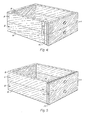
- Fig. 4 illustrates yet another alternate embodiment of the attachment apparatus of the present invention.
- a dovetail channel 70 is formed in one or more of the vertical, outer surfaces of the drawers A and B.
- the channel 70 is shown formed in a side panel 8 of the drawers.
- the dovetail channels 70 formed in the side panels 8 of the respective drawers are longitudinally aligned. It should be apparent that the dovetail channels 70 are formed in the side panels 8 so that when drawers A and B are vertically registered, the respective dovetail channels 70 are likewise aligned.
- a slat 72 formed and configured to be slidably received by the dovetail channel 70, is inserted in one of the dovetail channels.
- the slat 72 is positioned within the dovetail channels 70 of both drawers A and B, thereby joining the two drawers.
- the bottom panel 10 (not shown in Fig. 4) can then be removed from drawer A and the combination of the two drawers A, B used as one single drawer.
- the drawers A and B shown in Fig. 5 illustrate a method of joining the two drawers using grooves 74 and 76 respectively formed in the top and bottom peripheries of front panels 4.
- the grooves 74 and 76 are situated so as to be placed in confronting relation (i.e., the groove 74 of drawer B confronts groove 76 of drawer A) when the drawers A and B are vertically registered.
- a rib 78 configured to be slidably received by the hollow formed by the confronting grooves 74 and 76 of drawers B and A, respectively, is inserted in the grooves.
- the rib 78 is dimensioned to extend substantially the entire length of the grooves 74 and 76 (which themselves extend the full longitudinal length of the side panels 4), yet not protrude from the hollow when appropriately located therein - as illustrated in Fig. 5.
- the invention need not be limited to the use of only two vertically registered drawers constructed as described above.
- a plurality of drawers can be held in an appropriately constructed support st ruc - ture and used as desired to form one or more deeper drawers from a greater number of shallower drawers.
- the bottom panel 10 need not be removable, but could be structured to form the device used to combine the two drawers, as follows: The bottom panel 10 would be split along a line running down the center of the panel, parallel to the side panels 8, from the front panel 4 to the back panel 6, forming two substantially equally-dimensioned half-panels. Each half-panel would be hingedly attached to its respective side panel 8 so that the half-panels of a superposed drawer (i.e., drawer A) could swing into and be received by the underlying drawer (i.e., drawer B).
- a superposed drawer i.e., drawer A
- the underlying drawer i.e., drawer B
- a releasable hook-type latch or hooking apparatus can be used to attach and hold the two half-panels in a planar relation to each other, forming the bottom panel 10 of the overlying drawer.
Landscapes
- Drawers Of Furniture (AREA)
- Glass Compositions (AREA)
- Inorganic Insulating Materials (AREA)
- Fertilizers (AREA)
Priority Applications (3)
| Application Number | Priority Date | Filing Date | Title |
|---|---|---|---|
| DE8181301555T DE3171547D1 (en) | 1981-04-09 | 1981-04-09 | Combinable drawers |
| AT81301555T ATE14513T1 (de) | 1981-04-09 | 1981-04-09 | Zusammensetzbare schubladen. |
| EP81301555A EP0062711B1 (de) | 1981-04-09 | 1981-04-09 | Zusammensetzbare Schubladen |
Applications Claiming Priority (1)
| Application Number | Priority Date | Filing Date | Title |
|---|---|---|---|
| EP81301555A EP0062711B1 (de) | 1981-04-09 | 1981-04-09 | Zusammensetzbare Schubladen |
Publications (2)
| Publication Number | Publication Date |
|---|---|
| EP0062711A1 true EP0062711A1 (de) | 1982-10-20 |
| EP0062711B1 EP0062711B1 (de) | 1985-07-31 |
Family
ID=8188272
Family Applications (1)
| Application Number | Title | Priority Date | Filing Date |
|---|---|---|---|
| EP81301555A Expired EP0062711B1 (de) | 1981-04-09 | 1981-04-09 | Zusammensetzbare Schubladen |
Country Status (3)
| Country | Link |
|---|---|
| EP (1) | EP0062711B1 (de) |
| AT (1) | ATE14513T1 (de) |
| DE (1) | DE3171547D1 (de) |
Cited By (1)
| Publication number | Priority date | Publication date | Assignee | Title |
|---|---|---|---|---|
| EP2505100A1 (de) | 2011-03-28 | 2012-10-03 | Molteni & C. S.p.A. | Modular Möbelelement und Zusammenstellung mit so einem Möbelelement auffassende Aufstellung |
Citations (6)
| Publication number | Priority date | Publication date | Assignee | Title |
|---|---|---|---|---|
| DE435316C (de) * | 1921-06-22 | 1926-10-12 | Julius Mols | Aus einzelnen Kaesten zusammensetzbarer Schrank |
| DE1142222B (de) * | 1958-10-15 | 1963-01-10 | Fortschritt Buero Einrichtungs | Aus einem Holzrahmen bestehende Schublade mit doppelter Auszugsfuehrung zum Einsetzen von Karteikaesten od. dgl. |
| US3529878A (en) * | 1967-12-01 | 1970-09-22 | Kerridge Joinery Ltd | Case for storing articles |
| CH553052A (de) * | 1972-03-22 | 1974-08-30 | Utz Ag Georg | Verfahren zur herstellung von behaeltern aus kunststoff und nach diesem verfahren hergestellter behaelter. |
| FR2254180A5 (en) * | 1973-12-10 | 1975-07-04 | Guerin Gaston | Chest of drawers for pharmaceutical storage - have drawer heads sliding longitudinally and locking onto chassis and are of variable height |
| FR2300522A1 (fr) * | 1975-02-14 | 1976-09-10 | Buysse Andre | Elements modulaires pour la construction de pieces de mobilier |
-
1981
- 1981-04-09 DE DE8181301555T patent/DE3171547D1/de not_active Expired
- 1981-04-09 AT AT81301555T patent/ATE14513T1/de not_active IP Right Cessation
- 1981-04-09 EP EP81301555A patent/EP0062711B1/de not_active Expired
Patent Citations (6)
| Publication number | Priority date | Publication date | Assignee | Title |
|---|---|---|---|---|
| DE435316C (de) * | 1921-06-22 | 1926-10-12 | Julius Mols | Aus einzelnen Kaesten zusammensetzbarer Schrank |
| DE1142222B (de) * | 1958-10-15 | 1963-01-10 | Fortschritt Buero Einrichtungs | Aus einem Holzrahmen bestehende Schublade mit doppelter Auszugsfuehrung zum Einsetzen von Karteikaesten od. dgl. |
| US3529878A (en) * | 1967-12-01 | 1970-09-22 | Kerridge Joinery Ltd | Case for storing articles |
| CH553052A (de) * | 1972-03-22 | 1974-08-30 | Utz Ag Georg | Verfahren zur herstellung von behaeltern aus kunststoff und nach diesem verfahren hergestellter behaelter. |
| FR2254180A5 (en) * | 1973-12-10 | 1975-07-04 | Guerin Gaston | Chest of drawers for pharmaceutical storage - have drawer heads sliding longitudinally and locking onto chassis and are of variable height |
| FR2300522A1 (fr) * | 1975-02-14 | 1976-09-10 | Buysse Andre | Elements modulaires pour la construction de pieces de mobilier |
Cited By (1)
| Publication number | Priority date | Publication date | Assignee | Title |
|---|---|---|---|---|
| EP2505100A1 (de) | 2011-03-28 | 2012-10-03 | Molteni & C. S.p.A. | Modular Möbelelement und Zusammenstellung mit so einem Möbelelement auffassende Aufstellung |
Also Published As
| Publication number | Publication date |
|---|---|
| DE3171547D1 (en) | 1985-09-05 |
| EP0062711B1 (de) | 1985-07-31 |
| ATE14513T1 (de) | 1985-08-15 |
Similar Documents
| Publication | Publication Date | Title |
|---|---|---|
| US4285559A (en) | Combining drawers | |
| US7100999B2 (en) | System of interlocking storage and display modules connectable in a plurality of different configurations | |
| US4932538A (en) | Fixture support wall panel | |
| US6152553A (en) | Modular furniture construction system | |
| US4258856A (en) | Space dividing assembly | |
| US3529878A (en) | Case for storing articles | |
| US4206955A (en) | Closet storage unit | |
| GB1322583A (en) | Box furniture | |
| US4047777A (en) | Knockdown put-together article of furniture | |
| US3730605A (en) | Interchangeable side panel and the like for modular furniture | |
| US4371221A (en) | Composite modular element structure for furnishings | |
| US4867319A (en) | Drawer organizer with removable sections and blank therefor | |
| US6422398B2 (en) | Modular organizer | |
| CA1257851A (en) | Modular shelving system | |
| JP2002051852A (ja) | チェスト用多方向引き出し | |
| EP0062711B1 (de) | Zusammensetzbare Schubladen | |
| US2404182A (en) | Furniture | |
| US4387940A (en) | Apparatus for supportingly organizing and displaying miscellaneous articles | |
| JPH07163427A (ja) | 家具組立てキット | |
| US3450451A (en) | Portable,multiple-use cabinet | |
| WO1992005724A1 (en) | Interchangeable modular furniture | |
| US20020153813A1 (en) | Modular furniture construction system | |
| US4609235A (en) | Drawer for electrical cabinets | |
| US4356777A (en) | Knockdown structure | |
| JP2581739Y2 (ja) | 多目的ラック |
Legal Events
| Date | Code | Title | Description |
|---|---|---|---|
| PUAI | Public reference made under article 153(3) epc to a published international application that has entered the european phase |
Free format text: ORIGINAL CODE: 0009012 |
|
| AK | Designated contracting states |
Designated state(s): AT BE CH DE FR GB IT NL SE |
|
| 17P | Request for examination filed |
Effective date: 19830223 |
|
| ITF | It: translation for a ep patent filed | ||
| GRAA | (expected) grant |
Free format text: ORIGINAL CODE: 0009210 |
|
| AK | Designated contracting states |
Designated state(s): AT BE CH DE FR GB IT LI NL SE |
|
| PG25 | Lapsed in a contracting state [announced via postgrant information from national office to epo] |
Ref country code: SE Effective date: 19850731 Ref country code: LI Effective date: 19850731 Ref country code: CH Effective date: 19850731 Ref country code: AT Effective date: 19850731 |
|
| REF | Corresponds to: |
Ref document number: 14513 Country of ref document: AT Date of ref document: 19850815 Kind code of ref document: T |
|
| REF | Corresponds to: |
Ref document number: 3171547 Country of ref document: DE Date of ref document: 19850905 |
|
| ET | Fr: translation filed | ||
| REG | Reference to a national code |
Ref country code: CH Ref legal event code: PL |
|
| PLBE | No opposition filed within time limit |
Free format text: ORIGINAL CODE: 0009261 |
|
| STAA | Information on the status of an ep patent application or granted ep patent |
Free format text: STATUS: NO OPPOSITION FILED WITHIN TIME LIMIT |
|
| 26N | No opposition filed | ||
| PGFP | Annual fee paid to national office [announced via postgrant information from national office to epo] |
Ref country code: NL Payment date: 19870430 Year of fee payment: 7 |
|
| PG25 | Lapsed in a contracting state [announced via postgrant information from national office to epo] |
Ref country code: GB Effective date: 19890409 |
|
| PG25 | Lapsed in a contracting state [announced via postgrant information from national office to epo] |
Ref country code: BE Effective date: 19890430 |
|
| BERE | Be: lapsed |
Owner name: KOCH GEORGE BYRON Effective date: 19890430 |
|
| PG25 | Lapsed in a contracting state [announced via postgrant information from national office to epo] |
Ref country code: NL Effective date: 19891101 |
|
| GBPC | Gb: european patent ceased through non-payment of renewal fee | ||
| NLV4 | Nl: lapsed or anulled due to non-payment of the annual fee | ||
| PG25 | Lapsed in a contracting state [announced via postgrant information from national office to epo] |
Ref country code: FR Free format text: LAPSE BECAUSE OF NON-PAYMENT OF DUE FEES Effective date: 19891228 |
|
| PG25 | Lapsed in a contracting state [announced via postgrant information from national office to epo] |
Ref country code: DE Effective date: 19900103 |
|
| REG | Reference to a national code |
Ref country code: FR Ref legal event code: ST |