EP0062847B1 - Dispositif pour concentrer et transmettre l'énergie solaire - Google Patents
Dispositif pour concentrer et transmettre l'énergie solaire Download PDFInfo
- Publication number
- EP0062847B1 EP0062847B1 EP82102777A EP82102777A EP0062847B1 EP 0062847 B1 EP0062847 B1 EP 0062847B1 EP 82102777 A EP82102777 A EP 82102777A EP 82102777 A EP82102777 A EP 82102777A EP 0062847 B1 EP0062847 B1 EP 0062847B1
- Authority
- EP
- European Patent Office
- Prior art keywords
- light
- receiving end
- optical fibers
- face
- solar energy
- Prior art date
- Legal status (The legal status is an assumption and is not a legal conclusion. Google has not performed a legal analysis and makes no representation as to the accuracy of the status listed.)
- Expired
Links
Images

Classifications
-
- G—PHYSICS
- G02—OPTICS
- G02B—OPTICAL ELEMENTS, SYSTEMS OR APPARATUS
- G02B6/00—Light guides; Structural details of arrangements comprising light guides and other optical elements, e.g. couplings
-
- F—MECHANICAL ENGINEERING; LIGHTING; HEATING; WEAPONS; BLASTING
- F21—LIGHTING
- F21S—NON-PORTABLE LIGHTING DEVICES; SYSTEMS THEREOF; VEHICLE LIGHTING DEVICES SPECIALLY ADAPTED FOR VEHICLE EXTERIORS
- F21S11/00—Non-electric lighting devices or systems using daylight
-
- F—MECHANICAL ENGINEERING; LIGHTING; HEATING; WEAPONS; BLASTING
- F24—HEATING; RANGES; VENTILATING
- F24S—SOLAR HEAT COLLECTORS; SOLAR HEAT SYSTEMS
- F24S23/00—Arrangements for concentrating solar-rays for solar heat collectors
- F24S23/12—Light guides
-
- F—MECHANICAL ENGINEERING; LIGHTING; HEATING; WEAPONS; BLASTING
- F24—HEATING; RANGES; VENTILATING
- F24S—SOLAR HEAT COLLECTORS; SOLAR HEAT SYSTEMS
- F24S23/00—Arrangements for concentrating solar-rays for solar heat collectors
- F24S23/30—Arrangements for concentrating solar-rays for solar heat collectors with lenses
-
- G—PHYSICS
- G02—OPTICS
- G02B—OPTICAL ELEMENTS, SYSTEMS OR APPARATUS
- G02B27/00—Optical systems or apparatus not provided for by any of the groups G02B1/00 - G02B26/00, G02B30/00
-
- G—PHYSICS
- G02—OPTICS
- G02B—OPTICAL ELEMENTS, SYSTEMS OR APPARATUS
- G02B6/00—Light guides; Structural details of arrangements comprising light guides and other optical elements, e.g. couplings
- G02B6/24—Coupling light guides
- G02B6/26—Optical coupling means
- G02B6/32—Optical coupling means having lens focusing means positioned between opposed fibre ends
-
- Y—GENERAL TAGGING OF NEW TECHNOLOGICAL DEVELOPMENTS; GENERAL TAGGING OF CROSS-SECTIONAL TECHNOLOGIES SPANNING OVER SEVERAL SECTIONS OF THE IPC; TECHNICAL SUBJECTS COVERED BY FORMER USPC CROSS-REFERENCE ART COLLECTIONS [XRACs] AND DIGESTS
- Y02—TECHNOLOGIES OR APPLICATIONS FOR MITIGATION OR ADAPTATION AGAINST CLIMATE CHANGE
- Y02E—REDUCTION OF GREENHOUSE GAS [GHG] EMISSIONS, RELATED TO ENERGY GENERATION, TRANSMISSION OR DISTRIBUTION
- Y02E10/00—Energy generation through renewable energy sources
- Y02E10/40—Solar thermal energy, e.g. solar towers
-
- Y—GENERAL TAGGING OF NEW TECHNOLOGICAL DEVELOPMENTS; GENERAL TAGGING OF CROSS-SECTIONAL TECHNOLOGIES SPANNING OVER SEVERAL SECTIONS OF THE IPC; TECHNICAL SUBJECTS COVERED BY FORMER USPC CROSS-REFERENCE ART COLLECTIONS [XRACs] AND DIGESTS
- Y02—TECHNOLOGIES OR APPLICATIONS FOR MITIGATION OR ADAPTATION AGAINST CLIMATE CHANGE
- Y02P—CLIMATE CHANGE MITIGATION TECHNOLOGIES IN THE PRODUCTION OR PROCESSING OF GOODS
- Y02P60/00—Technologies relating to agriculture, livestock or agroalimentary industries
- Y02P60/12—Technologies relating to agriculture, livestock or agroalimentary industries using renewable energies, e.g. solar water pumping
-
- Y—GENERAL TAGGING OF NEW TECHNOLOGICAL DEVELOPMENTS; GENERAL TAGGING OF CROSS-SECTIONAL TECHNOLOGIES SPANNING OVER SEVERAL SECTIONS OF THE IPC; TECHNICAL SUBJECTS COVERED BY FORMER USPC CROSS-REFERENCE ART COLLECTIONS [XRACs] AND DIGESTS
- Y10—TECHNICAL SUBJECTS COVERED BY FORMER USPC
- Y10S—TECHNICAL SUBJECTS COVERED BY FORMER USPC CROSS-REFERENCE ART COLLECTIONS [XRACs] AND DIGESTS
- Y10S385/00—Optical waveguides
- Y10S385/90—Solar collector or transmitter
Definitions
- the present invention relates to an apparatus for collecting and transmitting solar energy according to the pre-characterizing part of claim 1 or claim 6.
- the transmitted solar energy may then be used for predetermined purposes.
- This conventional solar energy utilization technique is mainly concerned with solar energy defined as the gross energy and with improvement of utilization efficiency of the gross solar energy.
- light components necessary for this purpose are preferably selectively collected and transmitted.
- white light which contains all components is preferably used.
- solar energy may be utilized for growing plants at the bottom of the sea. As a matter of fact, only bluish green light components reach the deep sea (100 m deep or more), and plants which grow with bluish green light components grow at the deep sea. On the other hand, since red light components are transmitted to the shallow sea, the plants which grow with red light components grow in the shallow sea.
- a lens system is used to focus the beam of sunlight.
- an optical fiber cable is used and one end thereof is positioned on a focal position of the lens.
- one end of the optical fiber cable is positioned on the focal position of the lens which corresponds to the selected light component of a color.
- a structure is adopted wherein one end of the optical fiber cable can be moved along an optical axis of light focused by the lens and can be fixed.
- a cable which comprises a plurality of optical fibers is used. Each end face of the optical fibers is positioned at each focal position of the light components of the selected colors.
- Fig. 1 is a view of an optical system of an apparatus for collecting and transmitting solar energy according to one embodiment of the present invention.
- Reference numeral 1 denotes a lens such as a Fresnel lens.
- Reference numeral 2 denotes a light guide which receives a beam of sunlight focused by the lens 1 and transmits the beam to a desired place.
- the beam of sunlight is focused by the lens 1
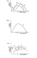
- an image of sun has a central region A of substantially white light and a peripheral region B of the light component focused on this focal position, as shown in Fig. 2.
- the focal position and the size of the image of the sun may vary with wavelength.
- the image of the sun is focused at a position P and has a diameter D 1 .
- the image of the sun is focused at a position P 2 and has a diameter D 2 .
- red light components which have long wavelengths the image of the sun is focused at a position P 3 and has a diameter D 3 . Therefore, if the light-receiving end face of the light guide 2 is positioned at the position'?, the light beam which contains the blue light components at the peripheral region B can be transmitted. If the light-receiving end face of the light guide 2 is positioned at the position P 2 , the light beam which contains the green light components at the peripheral region B can be transmitted.
- the light-receiving end face of the light guide 2 when the light-receiving end face of the light guide 2 is positioned at the position P 3 , the light beam which contains the red light components at the peripheral region B can be transmitted.
- the diameter of the light guide is selected to be the diameter D 1 for blue, the diameter D 2 for green and the diameter D 3 for red, the amount of the light guide is minimized for optimal transmission of the light beam which contains desired light components in a great amount.
- the diameter of the light-receiving end face of the light guide 2 may be enlarged to a diameter Do for transmitting all light components of the beam.
- the light-receiving end face of the light guide may be aligned with the focal position of the lens in the manufacturing process at the factory.
- the light-receiving end face of the light guide may be disposed to be adjustable along the optical axis of the lens. Then, the user can adjust the position of the light-receiving end face and fix it at a desired position in accordance with the light components of the desired color.
- the peripheral region B is radiated with different light components in accordance with the distance between the light-receiving end face and the focal position. If the focal position of the light component is close to the lens 1, the peripheral region B is radiated with the blue light components.
- the peripheral region B is radiated with the red light components.
- the area of the peripheral region B is larger than that of the central region A. Light energy radiated on the peripheral region B cannot be neglected. Further, the light component of the selected color is radiated on the peripheral region B. Thus, if the light components radiated on the peripheral region B are effectively used, great effects are obtained for a specific purpose.
- Fig. 3 is a graph representing the spectral distributions of sunlight.
- Reference symbol B denotes the spectral distribution of blue light components
- G the spectral distribution of green light components
- R the spectral distribution of red light components.
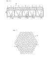
- Fig. 6 is a schematic sectional view of the main part of an apparatus for collecting and transmitting solar energy according to another embodiment of the present invention and Fig. 7 is a plan view thereof.
- Reference numeral 10 denotes lens arrays each comprising a number of small lenses 11 of 4 cm in diameter which collect solar energy.
- Reference numeral 20 denotes optical fibers of 0.2 mm in diameter which are respectively disposed in correspondance with the small lenses 11.
- Reference numeral 30 denotes a holding member for holding lenses 11 and the optical fibers 20.
- Each lens array 10 comprising a number of small lenses 11 which are disposed integrally therewith in the embodiment shown in the figure.
- the lens array 10 may be constituted by integrally adhering small lenses 11 with an adhesive or the like.
- the holding member 30 may include one portion which holds lenses and the other portion which holds optical fibers. Holes 31 are formed at a vicinity of the focal position of each lens 11 of the holding member 30. After the lenses 11 are fixed on the holding member 30, parallel light beams radiated on the lenses 11 are focused on the axes of the holes 31, respectively. However, focal positions vary in accordance with wavelength. Therefore, the optical fibers are respectively inserted into the holes 31 and the focal positions of the light components are respectively determined. The optical fibers 20 are respectively fixed on the respective focal positions of the light components. Thus, the light component of a desired color is introduced to each optical fiber 20.
- the end faces of the optical fibers in a predetermined number are aligned with the focal position of the red light components and the end faces of the rest of the optical fibers (optical fibers corresponding to lenses B, as shown in Fig. 7) are aligned with the focal positions of the blue light components, since the blue and red light components are especially required for culture of chlorella as described above.
- Other ends of the optical fibers are extended to a culture tank of chlorella. Thus, only the light components suitable for culture of chlorella are transmitted.
- Fig. 7 is a plan view of the structure of Fig. 6.
- Fig. 7 shows an example of the structure wherein small lenses are aligned in an area corresponding to that of the Fresnel lens of 35 cm diameter.
- regular hexagonal lenses 11 the greatest number of lenses are arranged in the unit area. For example, if the length of the diagonal line of each lens 11 is 4 cm, sixty-one lenses 11 can be effectively arranged.
- the lens arrays 10 which are constituted by the regular hexagonal lenses 11 are arranged substantially in a regular hexagonal shape, as shown in Fig. 7. If the lens arrays 10 of Fig.
- the regular hexagonal lenses are used for optimal arrangement.
- the present invention is not limited to the use of the regular hexagonal lenses.
- a round or rectangular lens may be utilized.
- Each small lens may be a Fresnel or spherical lens.
- the light guides are arranged in a great number and the proper alignment of the light-receiving end face of each light guide with each focal position of the lens is time-consuming and cumbersome.
- the specifications of the apparatus are determined for specific applications in advance.
- the light-receiving end faces of the light guides are fixed on the focal positions of the lenses in the manufacturing process, respectively, in order to eliminate the time-consuming operation by the user.
- the light guides for receiving the red light components may be supported by a single base and the light guides which receives the blue light components may be supported by another single base. These bases may then be arranged to be adjustable on the optical axis of the lenses.
Landscapes
- Engineering & Computer Science (AREA)
- Physics & Mathematics (AREA)
- Life Sciences & Earth Sciences (AREA)
- Sustainable Development (AREA)
- General Engineering & Computer Science (AREA)
- Combustion & Propulsion (AREA)
- Thermal Sciences (AREA)
- Chemical & Material Sciences (AREA)
- Sustainable Energy (AREA)
- Mechanical Engineering (AREA)
- General Physics & Mathematics (AREA)
- Optics & Photonics (AREA)
- Optical Couplings Of Light Guides (AREA)
- Cultivation Of Plants (AREA)
- Light Guides In General And Applications Therefor (AREA)
- Photovoltaic Devices (AREA)
Claims (10)
Applications Claiming Priority (2)
| Application Number | Priority Date | Filing Date | Title |
|---|---|---|---|
| JP49797/81 | 1981-04-02 | ||
| JP56049797A JPS6059567B2 (ja) | 1981-04-02 | 1981-04-02 | 太陽光収集装置 |
Publications (2)
| Publication Number | Publication Date |
|---|---|
| EP0062847A1 EP0062847A1 (fr) | 1982-10-20 |
| EP0062847B1 true EP0062847B1 (fr) | 1984-10-03 |
Family
ID=12841132
Family Applications (1)
| Application Number | Title | Priority Date | Filing Date |
|---|---|---|---|
| EP82102777A Expired EP0062847B1 (fr) | 1981-04-02 | 1982-04-01 | Dispositif pour concentrer et transmettre l'énergie solaire |
Country Status (7)
| Country | Link |
|---|---|
| US (1) | US4461278A (fr) |
| EP (1) | EP0062847B1 (fr) |
| JP (1) | JPS6059567B2 (fr) |
| KR (1) | KR850001561B1 (fr) |
| AU (1) | AU552323B2 (fr) |
| DE (1) | DE3260870D1 (fr) |
| NZ (1) | NZ200100A (fr) |
Families Citing this family (41)
| Publication number | Priority date | Publication date | Assignee | Title |
|---|---|---|---|---|
| JPS5968706A (ja) * | 1982-10-12 | 1984-04-18 | Takenaka Komuten Co Ltd | 集光装置 |
| JPS59133516A (ja) * | 1983-01-20 | 1984-07-31 | Takashi Mori | 光導体の受光端をレンズの焦点に合わせるための装置 |
| US4643524A (en) * | 1983-02-14 | 1987-02-17 | Kei Mori | Method of using a condensing lens |
| JPS606189A (ja) * | 1983-06-24 | 1985-01-12 | Takashi Mori | クロレラ培養装置 |
| JPS606911A (ja) * | 1983-06-24 | 1985-01-14 | Takashi Mori | 太陽光収集装置 |
| JPS6064315A (ja) * | 1983-09-19 | 1985-04-12 | Takashi Mori | 太陽光収集装置 |
| JPS60104912A (ja) * | 1983-11-11 | 1985-06-10 | Takashi Mori | 光導体管及びその接続具 |
| US4723826A (en) * | 1984-08-29 | 1988-02-09 | Whitaker Ranald O | Lens type solar collector requiring no orientation system |
| JPS6161101A (ja) * | 1984-08-31 | 1986-03-28 | Takashi Mori | 集光レンズ |
| JPS6161125A (ja) * | 1984-08-31 | 1986-03-28 | Takashi Mori | 太陽エネルギ−収集装置 |
| IT1182328B (it) * | 1984-12-19 | 1987-10-05 | Cselt Centro Studi Lab Telecom | Accoppiatore per fibre ottiche |
| JPS61216620A (ja) * | 1985-03-19 | 1986-09-26 | 森 敬 | 生物育成装置 |
| JPS62212608A (ja) * | 1986-03-14 | 1987-09-18 | Mitsubishi Rayon Co Ltd | 光フアイバ−用コリメ−タ−素子 |
| US4943125A (en) * | 1989-01-26 | 1990-07-24 | Laundre John W | Solar collector |
| US6724536B2 (en) | 1990-05-18 | 2004-04-20 | University Of Arkansas | Directional image lenticular window sheet |
| US6870681B1 (en) | 1992-09-21 | 2005-03-22 | University Of Arkansas, N.A. | Directional image transmission sheet and method of making same |
| US5680734A (en) * | 1990-05-18 | 1997-10-28 | University Of Arkansas N.A. | Solar energy control film and process |
| US5933276A (en) * | 1994-04-13 | 1999-08-03 | Board Of Trustees, University Of Arkansas, N.A. | Aberration-free directional image window sheet |
| JPH09327524A (ja) * | 1996-06-13 | 1997-12-22 | Hamamatsu Photonics Kk | ベッド |
| JP2002289900A (ja) * | 2001-03-23 | 2002-10-04 | Canon Inc | 集光型太陽電池モジュール及び集光型太陽光発電システム |
| US20080000514A1 (en) * | 2006-06-30 | 2008-01-03 | Kuo-Len Lin | Solar Energy Concentrator |
| US20100032005A1 (en) * | 2008-08-08 | 2010-02-11 | Joseph Ford | System and method for solar energy capture |
| AU2009293000A1 (en) * | 2008-09-19 | 2010-03-25 | The Regents Of The University Of California | System and method for solar energy capture and related method of manufacturing |
| CN101751824B (zh) * | 2008-12-19 | 2012-06-20 | 鸿富锦精密工业(深圳)有限公司 | 显示装置 |
| US20100212716A1 (en) * | 2009-02-20 | 2010-08-26 | Scott Lerner | Solar radiation collection using dichroic surface |
| US20100212717A1 (en) * | 2009-02-20 | 2010-08-26 | Whitlock John P | Solar collector with optical waveguide |
| EP2228611A1 (fr) * | 2009-02-23 | 2010-09-15 | Reidy, Neil | Panneau solaire |
| US8290318B2 (en) * | 2009-04-21 | 2012-10-16 | Svv Technology Innovations, Inc. | Light trapping optical cover |
| KR100913341B1 (ko) * | 2009-04-23 | 2009-08-20 | 김주수 | 실내 채광용 태양광 집광장치 |
| US7895790B2 (en) * | 2009-04-23 | 2011-03-01 | Chien-Feng Lin | Algae cultivation apparatus |
| CN101619897B (zh) * | 2009-07-27 | 2011-07-27 | 赵明生 | 准直式太阳能收集装置 |
| US8928988B1 (en) | 2011-04-01 | 2015-01-06 | The Regents Of The University Of California | Monocentric imaging |
| CN102298174B (zh) * | 2011-09-02 | 2012-11-07 | 陕西科技大学 | 一种分光型阳光输送机 |
| CN102313932B (zh) * | 2011-09-02 | 2013-02-13 | 陕西科技大学 | 一种太阳能聚光光导纤维接口装置 |
| CN102305961B (zh) * | 2011-09-02 | 2013-02-13 | 陕西科技大学 | 一种太阳能聚光接口装置 |
| US8857425B2 (en) * | 2011-09-19 | 2014-10-14 | Cyrous Gheyri | Solar lens water heating system |
| TWI524542B (zh) * | 2011-11-01 | 2016-03-01 | 鴻海精密工業股份有限公司 | 太陽能應用裝置及太陽能應用方法 |
| US10505059B2 (en) | 2015-01-16 | 2019-12-10 | The Arizona Board Of Regents On Behalf Of The University Of Arizona | Micro-scale concentrated photovoltaic module |
| WO2016141041A1 (fr) | 2015-03-02 | 2016-09-09 | The Arizona Board Of Regents On Behalf Of The University Of Arizona | Moule de formation de verre de forme ajustable |
| WO2016200988A1 (fr) | 2015-06-12 | 2016-12-15 | The Arizona Board Of Regents On Behalf Of The University Of Arizona | Module photovoltaïque en tandem avec séparation spectrale diffractive |
| WO2017024038A1 (fr) | 2015-08-03 | 2017-02-09 | The Arizona Board Of Regents On Behalf Of The University Of Arizona | Concentrateur solaire pour récepteur central monté sur une tour |
Family Cites Families (8)
| Publication number | Priority date | Publication date | Assignee | Title |
|---|---|---|---|---|
| US3185021A (en) * | 1961-03-27 | 1965-05-25 | Thompson Ramo Wooldridge Inc | Focal isolation monochromator employing accentuation of longitudinal chromatic aberration |
| US3885879A (en) * | 1973-06-25 | 1975-05-27 | Fisher Scientific Co | Dual beam spectrophotometer utilizing a spectral wedge and bifurcated fiber optic bundle |
| JPS5414031A (en) * | 1977-07-04 | 1979-02-01 | Mitsubishi Heavy Ind Ltd | Optical-fiber-used solar energy collector |
| JPS5546341A (en) * | 1978-09-28 | 1980-04-01 | Muneaki Okuyama | Light heater |
| DE2918024C2 (de) * | 1979-05-04 | 1981-07-30 | Licentia Patent-Verwaltungs-Gmbh, 6000 Frankfurt | Justiereinrichtung für eine Lichtleitfaserverbindung mit Linsenkopplung |
| DE2934847A1 (de) * | 1979-08-29 | 1981-03-19 | Schmols, Karl-Heinz, 2808 Syke | Anlagen zur nutzung der sonnenenergie |
| US4257401A (en) * | 1980-01-02 | 1981-03-24 | Daniels Ronald M | Solar heat collector |
| US4403152A (en) * | 1981-05-18 | 1983-09-06 | General Electric Company | Optical fiber position sensor |
-
1981
- 1981-04-02 JP JP56049797A patent/JPS6059567B2/ja not_active Expired
-
1982
- 1982-02-22 KR KR8200759A patent/KR850001561B1/ko not_active Expired
- 1982-03-23 NZ NZ200100A patent/NZ200100A/en unknown
- 1982-03-25 US US06/361,892 patent/US4461278A/en not_active Expired - Lifetime
- 1982-03-31 AU AU82201/82A patent/AU552323B2/en not_active Ceased
- 1982-04-01 EP EP82102777A patent/EP0062847B1/fr not_active Expired
- 1982-04-01 DE DE8282102777T patent/DE3260870D1/de not_active Expired
Also Published As
| Publication number | Publication date |
|---|---|
| JPS57164702A (en) | 1982-10-09 |
| AU552323B2 (en) | 1986-05-29 |
| KR830009505A (ko) | 1983-12-21 |
| KR850001561B1 (ko) | 1985-10-17 |
| EP0062847A1 (fr) | 1982-10-20 |
| US4461278A (en) | 1984-07-24 |
| JPS6059567B2 (ja) | 1985-12-25 |
| NZ200100A (en) | 1984-07-31 |
| DE3260870D1 (en) | 1984-11-08 |
| AU8220182A (en) | 1982-10-07 |
Similar Documents
| Publication | Publication Date | Title |
|---|---|---|
| EP0062847B1 (fr) | Dispositif pour concentrer et transmettre l'énergie solaire | |
| US4653472A (en) | Solar ray energy collecting device | |
| GB2222273A (en) | "light radiator". | |
| US5005931A (en) | Light radiator | |
| WO1979000282A1 (fr) | Methode de dispersion d'un rayon de lumiere dans un milieu de culture liquide | |
| JPS59133507A (ja) | 人工光源装置 | |
| AU4701097A (en) | Light-transmitting device | |
| US4984862A (en) | Light radiator for the cultivation of fish | |
| JPS628762B2 (fr) | ||
| KR890003298B1 (ko) | 인공 광원 장치 | |
| EP0071052B1 (fr) | Méthode et dispositif pour la dispersion de lumière collimatée sortant d'un guide de lumière | |
| CA2007008A1 (fr) | Dispositif de distribution de lumiere | |
| US4844598A (en) | Light focusing lens with centrally disposed light intercepting member | |
| CA1259215A (fr) | Construction integree d'un fort nombre de cables a conducteurs optiques | |
| CA1207695A (fr) | Appareil de photosynthese | |
| JPS6258704B2 (fr) | ||
| JPS6180114A (ja) | 人工光源装置 | |
| RU1285947C (ru) | Осветитель | |
| JPS61122609A (ja) | 太陽光伝送装置における光フアイバ− | |
| JPH033922Y2 (fr) | ||
| KR900002582Y1 (ko) | 집광 렌즈 | |
| JPS6147265U (ja) | 植物育成箱の単色光強エネルギ−複合照射装置 | |
| KR20250156571A (ko) | 광발전 장치 및 채광 장치를 구비한 태양광 이용 시스템 | |
| JPS5917976A (ja) | クロレラ培養装置 | |
| JPS5917977A (ja) | クロレラ培養装置 |
Legal Events
| Date | Code | Title | Description |
|---|---|---|---|
| PUAI | Public reference made under article 153(3) epc to a published international application that has entered the european phase |
Free format text: ORIGINAL CODE: 0009012 |
|
| 17P | Request for examination filed |
Effective date: 19820429 |
|
| AK | Designated contracting states |
Designated state(s): CH DE FR GB IT SE |
|
| ITF | It: translation for a ep patent filed | ||
| GRAA | (expected) grant |
Free format text: ORIGINAL CODE: 0009210 |
|
| AK | Designated contracting states |
Designated state(s): CH DE FR GB IT LI SE |
|
| REF | Corresponds to: |
Ref document number: 3260870 Country of ref document: DE Date of ref document: 19841108 |
|
| ET | Fr: translation filed | ||
| PLBE | No opposition filed within time limit |
Free format text: ORIGINAL CODE: 0009261 |
|
| STAA | Information on the status of an ep patent application or granted ep patent |
Free format text: STATUS: NO OPPOSITION FILED WITHIN TIME LIMIT |
|
| 26N | No opposition filed | ||
| ITTA | It: last paid annual fee | ||
| PGFP | Annual fee paid to national office [announced via postgrant information from national office to epo] |
Ref country code: GB Payment date: 19900331 Year of fee payment: 9 |
|
| PGFP | Annual fee paid to national office [announced via postgrant information from national office to epo] |
Ref country code: SE Payment date: 19900423 Year of fee payment: 9 |
|
| PG25 | Lapsed in a contracting state [announced via postgrant information from national office to epo] |
Ref country code: GB Effective date: 19910401 |
|
| PG25 | Lapsed in a contracting state [announced via postgrant information from national office to epo] |
Ref country code: SE Effective date: 19910402 |
|
| GBPC | Gb: european patent ceased through non-payment of renewal fee | ||
| EUG | Se: european patent has lapsed |
Ref document number: 82102777.8 Effective date: 19911108 |
|
| PGFP | Annual fee paid to national office [announced via postgrant information from national office to epo] |
Ref country code: FR Payment date: 19990324 Year of fee payment: 18 |
|
| PGFP | Annual fee paid to national office [announced via postgrant information from national office to epo] |
Ref country code: CH Payment date: 19990325 Year of fee payment: 18 |
|
| PGFP | Annual fee paid to national office [announced via postgrant information from national office to epo] |
Ref country code: DE Payment date: 19990326 Year of fee payment: 18 |
|
| PG25 | Lapsed in a contracting state [announced via postgrant information from national office to epo] |
Ref country code: LI Free format text: LAPSE BECAUSE OF NON-PAYMENT OF DUE FEES Effective date: 20000430 Ref country code: CH Free format text: LAPSE BECAUSE OF NON-PAYMENT OF DUE FEES Effective date: 20000430 |
|
| REG | Reference to a national code |
Ref country code: CH Ref legal event code: PL |
|
| PG25 | Lapsed in a contracting state [announced via postgrant information from national office to epo] |
Ref country code: FR Free format text: LAPSE BECAUSE OF NON-PAYMENT OF DUE FEES Effective date: 20001229 |
|
| PG25 | Lapsed in a contracting state [announced via postgrant information from national office to epo] |
Ref country code: DE Free format text: LAPSE BECAUSE OF NON-PAYMENT OF DUE FEES Effective date: 20010201 |
|
| REG | Reference to a national code |
Ref country code: FR Ref legal event code: ST |