EP0062926B1 - Induktive Heizvorrichtung - Google Patents
Induktive Heizvorrichtung Download PDFInfo
- Publication number
- EP0062926B1 EP0062926B1 EP19820103183 EP82103183A EP0062926B1 EP 0062926 B1 EP0062926 B1 EP 0062926B1 EP 19820103183 EP19820103183 EP 19820103183 EP 82103183 A EP82103183 A EP 82103183A EP 0062926 B1 EP0062926 B1 EP 0062926B1
- Authority
- EP
- European Patent Office
- Prior art keywords
- heating coils
- inductive heating
- heating device
- distribution board
- heating
- Prior art date
- Legal status (The legal status is an assumption and is not a legal conclusion. Google has not performed a legal analysis and makes no representation as to the accuracy of the status listed.)
- Expired
Links
Images
Classifications
-
- H—ELECTRICITY
- H05—ELECTRIC TECHNIQUES NOT OTHERWISE PROVIDED FOR
- H05B—ELECTRIC HEATING; ELECTRIC LIGHT SOURCES NOT OTHERWISE PROVIDED FOR; CIRCUIT ARRANGEMENTS FOR ELECTRIC LIGHT SOURCES, IN GENERAL
- H05B6/00—Heating by electric, magnetic or electromagnetic fields
- H05B6/02—Induction heating
- H05B6/06—Control, e.g. of temperature, of power
- H05B6/08—Control, e.g. of temperature, of power using compensating or balancing arrangements
Definitions
- the present invention relates to an inductive heating device in which a plurality of heating coils are selectively connected to a distribution board having at least one compensating capacitor for inductive heating of a workpiece.
- Such a device is known from LEW-Nach Process No. 17,1975, pp 27-30.
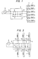
- FIG. 1 A further conventional inductive heating device of the same general type to which the invention pertains is shown in Fig. 1.
- reference numeral 1 designates a plurality of heating coils
- 2 switches for selectively activating the heating coils
- 3 power-factor enhancing capacitors forming a parallel resonance circuit for compensating for the lag power factors of the heating coils 1,4 a matching board on which the capacitors 3 are mounted
- 5 a power source for supplying electrical power to the input terminal 6 of the matching board 4
- this heating device workpieces to be heated (not shown) are placed inside the heating coils.
- a processing cycle of loading a workpiece, heating the workpiece, cooling the workpiece and loading another workpiece is employed.
- switches 2 are provided to selectively switch the heating coils 1, with one switch being closed to connect a single coil to the matching board at any time.
- heating coils 1 having, for example, a diameter of 500 to 3000 mm and a length of 500 to 5000 mm are provided and current is supplied to one heating coil at a time, sometimes it is impossible to supply current effectively to the heating coil which is farthest from the matching board 4 because of power transmission losses caused by power line voltage drops.
- LEW-Nachzinka No. 17 1975, pages 27-30 discloses a voltage adjusting arrangement for medium frequency induction heating apparatus.
- the disclosure includes a bus bar compensation arrangement to which the various heating coils may be selectively connected.
- each heating coil has its own compensating capacitance and thus represents a balanced load. It is true that further capacitances are connected directly to the bus bar, but these serve only for compensation of the bus bar itself and of the generators so far as this is necessary. Furthermore, no current return lines for the heating coils are illustrated. Therefore, this disclosure does not relate to a matching board for compensating impedances of the coils connected thereto and therefore provides no solution to problems arising with such a matching board as discussed with reference to Figure 1.
- the bus bar arrangement serves only to distribute power to the coils.
- An object of the present invention is to provide an inductive heating device employing a matching board for supplying a plurality of heating coils by which board proper matching may be achieved for each coil without undue power transmission losses in the supply lines.
- the device defined in the first paragraph of this specification is characterised in that a plurality of pairs of output terminals are provided on said distribution board for respective ones of said heating coils, in that the distribution board is provided with two conductive lines across which said at least one capacitor is connected, and in that the output terminals of each said pair are connected to respective conductive lines and thereby to said at least one capacitor, whereby said distribution board provides capacitive compensation or matching for said heating coils.
- reference numerals 1 through 6 and 8 designate components identified by the same reference numerals as in Fig. 1.
- Reference numerals 10 through 15 designate output terminal pairs which are provided on the matching board 4 and are connected to the current collecting line 8. THe pairs of output terminals 10 through 15 are connected through the switches 2 to corresponding ones of the heating coils 1.
- the common current collecting line 8 merely functions to collect the currents from the various capacitors 3.
- the common current collecting line 8 serves as the current supplying lines (which are also provided in the conventional device) because a plurality of output terminals 10 through 15, each of which can be selectively connected to a separate one of the heating coils 1, are provided on the matching board 4.
- connections are also provided directly between adjacent ones of said output terminals, i.e. one line of terminal pair 10 would be connected to the corresponding lines 11 and so on.
- connecting bus bars can be employed instead of the switches 2.
Landscapes
- Physics & Mathematics (AREA)
- Electromagnetism (AREA)
- General Induction Heating (AREA)
Claims (3)
Applications Claiming Priority (2)
| Application Number | Priority Date | Filing Date | Title |
|---|---|---|---|
| JP5429581U JPS6324634Y2 (de) | 1981-04-15 | 1981-04-15 | |
| JP54295/81U | 1981-04-15 |
Publications (2)
| Publication Number | Publication Date |
|---|---|
| EP0062926A1 EP0062926A1 (de) | 1982-10-20 |
| EP0062926B1 true EP0062926B1 (de) | 1987-08-12 |
Family
ID=12966571
Family Applications (1)
| Application Number | Title | Priority Date | Filing Date |
|---|---|---|---|
| EP19820103183 Expired EP0062926B1 (de) | 1981-04-15 | 1982-04-15 | Induktive Heizvorrichtung |
Country Status (3)
| Country | Link |
|---|---|
| EP (1) | EP0062926B1 (de) |
| JP (1) | JPS6324634Y2 (de) |
| DE (1) | DE3276996D1 (de) |
Family Cites Families (1)
| Publication number | Priority date | Publication date | Assignee | Title |
|---|---|---|---|---|
| DE1185744B (de) * | 1958-04-14 | 1965-01-21 | Aeg | Induktionsanlage mit mindestens zwei ueber eine Sammelschiene gespeisten Heizstationen mit mehreren aufeinanderfolgenden, mit verschiedenen Leistungen und unterschiedlichen Frequenzen arbeitenden Erwaermungszonen zum regelbaren Erwaermen von metallischen Werkstuecken |
-
1981
- 1981-04-15 JP JP5429581U patent/JPS6324634Y2/ja not_active Expired
-
1982
- 1982-04-15 EP EP19820103183 patent/EP0062926B1/de not_active Expired
- 1982-04-15 DE DE8282103183T patent/DE3276996D1/de not_active Expired
Also Published As
| Publication number | Publication date |
|---|---|
| EP0062926A1 (de) | 1982-10-20 |
| DE3276996D1 (en) | 1987-09-17 |
| JPS6324634Y2 (de) | 1988-07-06 |
| JPS57167590U (de) | 1982-10-22 |
Similar Documents
| Publication | Publication Date | Title |
|---|---|---|
| KR970704263A (ko) | 파워 인버터를 위한 개선된 전자기 방해 필터 토폴로지 | |
| AU3155493A (en) | Modular AC drive controller | |
| US6111328A (en) | Switching assembly | |
| CA1124788A (en) | High current low voltage liquid cooled switching regulator dc power supply | |
| US5835354A (en) | Compact modular structure for electrical converters | |
| GB2243755A (en) | Induction heating apparatus | |
| JP2017099089A (ja) | ワイヤレス伝送装置 | |
| US4918591A (en) | High frequency interference suppression filter for circuits to be connected to a conductor | |
| AU2014321674B2 (en) | A modular, scalable, multi-function, power quality system for utility networks | |
| US5812365A (en) | Mounting device for power capacitor banks | |
| EP0062926A1 (de) | Induktive Heizvorrichtung | |
| US20220368155A1 (en) | Power Supply Assembly and Switch Assembly | |
| JPH03277182A (ja) | インバータ | |
| EP0848895B1 (de) | Ausgleichvorrichtung bei induktiver last, bestimmt zum parallel-erwaermen von mehreren teilen | |
| EP0145317B1 (de) | Parallele Erdungsschaltung | |
| US3118040A (en) | H. f. dielectric heating apparatus | |
| US4703195A (en) | Parallel grounding scheme | |
| US5257170A (en) | Electric converter with several induction coils | |
| CN210724575U (zh) | 一种高压功率单元及高压变频器 | |
| US1828291A (en) | Electric induction furnace | |
| CN107229315B (zh) | 一种计算设备 | |
| US4028608A (en) | Bridge circuit arrangement on electrical frequency converters which can be fed with a D.C. current | |
| CN216056793U (zh) | 一种多电容并联电路及供电电路板 | |
| US3899747A (en) | Arrangement for providing radio equipment with a plurality of oscillators | |
| US10777956B1 (en) | System for supplying electric power to a plurality of load circuit boards including a circuit for oscillation mitigation |
Legal Events
| Date | Code | Title | Description |
|---|---|---|---|
| PUAI | Public reference made under article 153(3) epc to a published international application that has entered the european phase |
Free format text: ORIGINAL CODE: 0009012 |
|
| AK | Designated contracting states |
Designated state(s): DE FR GB |
|
| 17P | Request for examination filed |
Effective date: 19830301 |
|
| GRAA | (expected) grant |
Free format text: ORIGINAL CODE: 0009210 |
|
| AK | Designated contracting states |
Kind code of ref document: B1 Designated state(s): DE FR GB |
|
| REF | Corresponds to: |
Ref document number: 3276996 Country of ref document: DE Date of ref document: 19870917 |
|
| ET | Fr: translation filed | ||
| PLBE | No opposition filed within time limit |
Free format text: ORIGINAL CODE: 0009261 |
|
| STAA | Information on the status of an ep patent application or granted ep patent |
Free format text: STATUS: NO OPPOSITION FILED WITHIN TIME LIMIT |
|
| 26N | No opposition filed | ||
| PGFP | Annual fee paid to national office [announced via postgrant information from national office to epo] |
Ref country code: GB Payment date: 19960409 Year of fee payment: 15 |
|
| PGFP | Annual fee paid to national office [announced via postgrant information from national office to epo] |
Ref country code: FR Payment date: 19960410 Year of fee payment: 15 |
|
| PGFP | Annual fee paid to national office [announced via postgrant information from national office to epo] |
Ref country code: DE Payment date: 19960418 Year of fee payment: 15 |
|
| PG25 | Lapsed in a contracting state [announced via postgrant information from national office to epo] |
Ref country code: GB Effective date: 19970415 |
|
| GBPC | Gb: european patent ceased through non-payment of renewal fee |
Effective date: 19970415 |
|
| PG25 | Lapsed in a contracting state [announced via postgrant information from national office to epo] |
Ref country code: FR Free format text: LAPSE BECAUSE OF NON-PAYMENT OF DUE FEES Effective date: 19971231 |
|
| PG25 | Lapsed in a contracting state [announced via postgrant information from national office to epo] |
Ref country code: DE Free format text: LAPSE BECAUSE OF NON-PAYMENT OF DUE FEES Effective date: 19980101 |
|
| REG | Reference to a national code |
Ref country code: FR Ref legal event code: ST |