EP0063025A1 - Hydraulischer Steuerkreis für einen Hydraulikzylinder - Google Patents
Hydraulischer Steuerkreis für einen Hydraulikzylinder Download PDFInfo
- Publication number
- EP0063025A1 EP0063025A1 EP82301825A EP82301825A EP0063025A1 EP 0063025 A1 EP0063025 A1 EP 0063025A1 EP 82301825 A EP82301825 A EP 82301825A EP 82301825 A EP82301825 A EP 82301825A EP 0063025 A1 EP0063025 A1 EP 0063025A1
- Authority
- EP
- European Patent Office
- Prior art keywords
- hydraulic
- ram
- valve
- lowering
- relief valve
- Prior art date
- Legal status (The legal status is an assumption and is not a legal conclusion. Google has not performed a legal analysis and makes no representation as to the accuracy of the status listed.)
- Withdrawn
Links
- 239000012530 fluid Substances 0.000 claims abstract description 19
- 230000000694 effects Effects 0.000 claims description 6
- 230000004044 response Effects 0.000 claims description 5
- 238000013022 venting Methods 0.000 claims description 5
- 238000010926 purge Methods 0.000 claims description 3
- 238000011010 flushing procedure Methods 0.000 claims 1
- 230000009471 action Effects 0.000 description 3
- 230000006835 compression Effects 0.000 description 2
- 238000007906 compression Methods 0.000 description 2
- 230000007812 deficiency Effects 0.000 description 2
- 238000010348 incorporation Methods 0.000 description 2
- 230000013011 mating Effects 0.000 description 2
- 230000001052 transient effect Effects 0.000 description 2
- 238000011144 upstream manufacturing Methods 0.000 description 2
- 230000003213 activating effect Effects 0.000 description 1
- 230000008901 benefit Effects 0.000 description 1
- 238000006073 displacement reaction Methods 0.000 description 1
- 238000005265 energy consumption Methods 0.000 description 1
- 230000000750 progressive effect Effects 0.000 description 1
- 230000009467 reduction Effects 0.000 description 1
- 238000009416 shuttering Methods 0.000 description 1
- 239000013589 supplement Substances 0.000 description 1
- 230000001502 supplementing effect Effects 0.000 description 1
- 210000000707 wrist Anatomy 0.000 description 1
Images

Classifications
-
- F—MECHANICAL ENGINEERING; LIGHTING; HEATING; WEAPONS; BLASTING
- F15—FLUID-PRESSURE ACTUATORS; HYDRAULICS OR PNEUMATICS IN GENERAL
- F15B—SYSTEMS ACTING BY MEANS OF FLUIDS IN GENERAL; FLUID-PRESSURE ACTUATORS, e.g. SERVOMOTORS; DETAILS OF FLUID-PRESSURE SYSTEMS, NOT OTHERWISE PROVIDED FOR
- F15B11/00—Servomotor systems without provision for follow-up action; Circuits therefor
- F15B11/08—Servomotor systems without provision for follow-up action; Circuits therefor with only one servomotor
-
- F—MECHANICAL ENGINEERING; LIGHTING; HEATING; WEAPONS; BLASTING
- F15—FLUID-PRESSURE ACTUATORS; HYDRAULICS OR PNEUMATICS IN GENERAL
- F15B—SYSTEMS ACTING BY MEANS OF FLUIDS IN GENERAL; FLUID-PRESSURE ACTUATORS, e.g. SERVOMOTORS; DETAILS OF FLUID-PRESSURE SYSTEMS, NOT OTHERWISE PROVIDED FOR
- F15B13/00—Details of servomotor systems ; Valves for servomotor systems
- F15B13/01—Locking-valves or other detent i.e. load-holding devices
- F15B13/015—Locking-valves or other detent i.e. load-holding devices using an enclosed pilot flow valve
-
- F—MECHANICAL ENGINEERING; LIGHTING; HEATING; WEAPONS; BLASTING
- F15—FLUID-PRESSURE ACTUATORS; HYDRAULICS OR PNEUMATICS IN GENERAL
- F15B—SYSTEMS ACTING BY MEANS OF FLUIDS IN GENERAL; FLUID-PRESSURE ACTUATORS, e.g. SERVOMOTORS; DETAILS OF FLUID-PRESSURE SYSTEMS, NOT OTHERWISE PROVIDED FOR
- F15B2211/00—Circuits for servomotor systems
- F15B2211/30—Directional control
- F15B2211/305—Directional control characterised by the type of valves
- F15B2211/30505—Non-return valves, i.e. check valves
- F15B2211/30515—Load holding valves
-
- F—MECHANICAL ENGINEERING; LIGHTING; HEATING; WEAPONS; BLASTING
- F15—FLUID-PRESSURE ACTUATORS; HYDRAULICS OR PNEUMATICS IN GENERAL
- F15B—SYSTEMS ACTING BY MEANS OF FLUIDS IN GENERAL; FLUID-PRESSURE ACTUATORS, e.g. SERVOMOTORS; DETAILS OF FLUID-PRESSURE SYSTEMS, NOT OTHERWISE PROVIDED FOR
- F15B2211/00—Circuits for servomotor systems
- F15B2211/40—Flow control
- F15B2211/405—Flow control characterised by the type of flow control means or valve
- F15B2211/40576—Assemblies of multiple valves
- F15B2211/40584—Assemblies of multiple valves the flow control means arranged in parallel with a check valve
-
- F—MECHANICAL ENGINEERING; LIGHTING; HEATING; WEAPONS; BLASTING
- F15—FLUID-PRESSURE ACTUATORS; HYDRAULICS OR PNEUMATICS IN GENERAL
- F15B—SYSTEMS ACTING BY MEANS OF FLUIDS IN GENERAL; FLUID-PRESSURE ACTUATORS, e.g. SERVOMOTORS; DETAILS OF FLUID-PRESSURE SYSTEMS, NOT OTHERWISE PROVIDED FOR
- F15B2211/00—Circuits for servomotor systems
- F15B2211/40—Flow control
- F15B2211/415—Flow control characterised by the connections of the flow control means in the circuit
- F15B2211/41527—Flow control characterised by the connections of the flow control means in the circuit being connected to an output member and a directional control valve
-
- F—MECHANICAL ENGINEERING; LIGHTING; HEATING; WEAPONS; BLASTING
- F15—FLUID-PRESSURE ACTUATORS; HYDRAULICS OR PNEUMATICS IN GENERAL
- F15B—SYSTEMS ACTING BY MEANS OF FLUIDS IN GENERAL; FLUID-PRESSURE ACTUATORS, e.g. SERVOMOTORS; DETAILS OF FLUID-PRESSURE SYSTEMS, NOT OTHERWISE PROVIDED FOR
- F15B2211/00—Circuits for servomotor systems
- F15B2211/50—Pressure control
- F15B2211/505—Pressure control characterised by the type of pressure control means
- F15B2211/50509—Pressure control characterised by the type of pressure control means the pressure control means controlling a pressure upstream of the pressure control means
- F15B2211/50518—Pressure control characterised by the type of pressure control means the pressure control means controlling a pressure upstream of the pressure control means using pressure relief valves
-
- F—MECHANICAL ENGINEERING; LIGHTING; HEATING; WEAPONS; BLASTING
- F15—FLUID-PRESSURE ACTUATORS; HYDRAULICS OR PNEUMATICS IN GENERAL
- F15B—SYSTEMS ACTING BY MEANS OF FLUIDS IN GENERAL; FLUID-PRESSURE ACTUATORS, e.g. SERVOMOTORS; DETAILS OF FLUID-PRESSURE SYSTEMS, NOT OTHERWISE PROVIDED FOR
- F15B2211/00—Circuits for servomotor systems
- F15B2211/50—Pressure control
- F15B2211/515—Pressure control characterised by the connections of the pressure control means in the circuit
- F15B2211/5153—Pressure control characterised by the connections of the pressure control means in the circuit being connected to an output member and a directional control valve
-
- F—MECHANICAL ENGINEERING; LIGHTING; HEATING; WEAPONS; BLASTING
- F15—FLUID-PRESSURE ACTUATORS; HYDRAULICS OR PNEUMATICS IN GENERAL
- F15B—SYSTEMS ACTING BY MEANS OF FLUIDS IN GENERAL; FLUID-PRESSURE ACTUATORS, e.g. SERVOMOTORS; DETAILS OF FLUID-PRESSURE SYSTEMS, NOT OTHERWISE PROVIDED FOR
- F15B2211/00—Circuits for servomotor systems
- F15B2211/50—Pressure control
- F15B2211/52—Pressure control characterised by the type of actuation
- F15B2211/528—Pressure control characterised by the type of actuation actuated by fluid pressure
-
- F—MECHANICAL ENGINEERING; LIGHTING; HEATING; WEAPONS; BLASTING
- F15—FLUID-PRESSURE ACTUATORS; HYDRAULICS OR PNEUMATICS IN GENERAL
- F15B—SYSTEMS ACTING BY MEANS OF FLUIDS IN GENERAL; FLUID-PRESSURE ACTUATORS, e.g. SERVOMOTORS; DETAILS OF FLUID-PRESSURE SYSTEMS, NOT OTHERWISE PROVIDED FOR
- F15B2211/00—Circuits for servomotor systems
- F15B2211/50—Pressure control
- F15B2211/56—Control of an upstream pressure
-
- F—MECHANICAL ENGINEERING; LIGHTING; HEATING; WEAPONS; BLASTING
- F15—FLUID-PRESSURE ACTUATORS; HYDRAULICS OR PNEUMATICS IN GENERAL
- F15B—SYSTEMS ACTING BY MEANS OF FLUIDS IN GENERAL; FLUID-PRESSURE ACTUATORS, e.g. SERVOMOTORS; DETAILS OF FLUID-PRESSURE SYSTEMS, NOT OTHERWISE PROVIDED FOR
- F15B2211/00—Circuits for servomotor systems
- F15B2211/50—Pressure control
- F15B2211/575—Pilot pressure control
-
- F—MECHANICAL ENGINEERING; LIGHTING; HEATING; WEAPONS; BLASTING
- F15—FLUID-PRESSURE ACTUATORS; HYDRAULICS OR PNEUMATICS IN GENERAL
- F15B—SYSTEMS ACTING BY MEANS OF FLUIDS IN GENERAL; FLUID-PRESSURE ACTUATORS, e.g. SERVOMOTORS; DETAILS OF FLUID-PRESSURE SYSTEMS, NOT OTHERWISE PROVIDED FOR
- F15B2211/00—Circuits for servomotor systems
- F15B2211/60—Circuit components or control therefor
- F15B2211/635—Circuits providing pilot pressure to pilot pressure-controlled fluid circuit elements
- F15B2211/6355—Circuits providing pilot pressure to pilot pressure-controlled fluid circuit elements having valve means
-
- F—MECHANICAL ENGINEERING; LIGHTING; HEATING; WEAPONS; BLASTING
- F15—FLUID-PRESSURE ACTUATORS; HYDRAULICS OR PNEUMATICS IN GENERAL
- F15B—SYSTEMS ACTING BY MEANS OF FLUIDS IN GENERAL; FLUID-PRESSURE ACTUATORS, e.g. SERVOMOTORS; DETAILS OF FLUID-PRESSURE SYSTEMS, NOT OTHERWISE PROVIDED FOR
- F15B2211/00—Circuits for servomotor systems
- F15B2211/70—Output members, e.g. hydraulic motors or cylinders or control therefor
- F15B2211/75—Control of speed of the output member
-
- F—MECHANICAL ENGINEERING; LIGHTING; HEATING; WEAPONS; BLASTING
- F15—FLUID-PRESSURE ACTUATORS; HYDRAULICS OR PNEUMATICS IN GENERAL
- F15B—SYSTEMS ACTING BY MEANS OF FLUIDS IN GENERAL; FLUID-PRESSURE ACTUATORS, e.g. SERVOMOTORS; DETAILS OF FLUID-PRESSURE SYSTEMS, NOT OTHERWISE PROVIDED FOR
- F15B2211/00—Circuits for servomotor systems
- F15B2211/80—Other types of control related to particular problems or conditions
- F15B2211/86—Control during or prevention of abnormal conditions
- F15B2211/863—Control during or prevention of abnormal conditions the abnormal condition being a hydraulic or pneumatic failure
- F15B2211/8636—Circuit failure, e.g. valve or hose failure
-
- F—MECHANICAL ENGINEERING; LIGHTING; HEATING; WEAPONS; BLASTING
- F15—FLUID-PRESSURE ACTUATORS; HYDRAULICS OR PNEUMATICS IN GENERAL
- F15B—SYSTEMS ACTING BY MEANS OF FLUIDS IN GENERAL; FLUID-PRESSURE ACTUATORS, e.g. SERVOMOTORS; DETAILS OF FLUID-PRESSURE SYSTEMS, NOT OTHERWISE PROVIDED FOR
- F15B2211/00—Circuits for servomotor systems
- F15B2211/80—Other types of control related to particular problems or conditions
- F15B2211/875—Control measures for coping with failures
- F15B2211/8752—Emergency operation mode, e.g. fail-safe operation mode
Definitions
- This invention relates to a hydraulic control circuit for a hydraulic ram (cylinder + piston) controlling raising and lowering of a mechanical member, more particularly but not exclusively for ram cylinder control of the boom of a hydraulic excavator.
- the over-centre valve is a pilot operated relief valve and is mounted on a ram cylinder.
- the pilot pressure used to control the valve is obtained from the feed line to the lowering side of the boom cylinders.
- An object of the present invention is to overcome or substantially reduce the abovementioned disadvantage.
- the present invention consists in an hydraulic control circuit for a hydraulic ram controlling raising and lowering of a mechanical member, comprising a source of hydraulic pressure, a selector valve for selectively connecting the hydraulic source to opposite sides of the ram whereby actuation of the selector valve operates the ram to raise or lower the mechanical member, a load control valve disposed adjacent to the ram and connected between the raising side of the ram and the selector valve, said load control valve comprising non-return valve means via which hydraulic pressure is applied to the raising side of the ram and hydraulically operated relief valve means for controlling the outlet of hydraulic fluid from said raising side when applying hydraulic fluid pressure to the lowering side and means responsive to a predetermined hydraulic fluid pressure or flow applied to the lowering side for supplying hydraulic fluid pressure to operate the relief valve means at a sufficient pressure to retain the relief valve means open as the lowering speed increases above that determined by the supply of hydraulic fluid pressure to the lowering side.
- the boom In hydraulic circuits constructed in accordance with the invention for boom ram control, the boom is either locked and prevented from falling after a hose burst or continues the selected movement in a controllable manner depending upon which hose bursts, the maximum speed of lowering of the boom under normal conditions is controlled at a speed faster than would be determined by the flow of oil into the lowering side of the ram cylinder, and boom-drift, i.e. lowering of the boom due to any leakage in the system, is prevented by the load control valve.
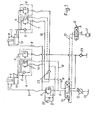
- the circuit shown in Figure 1 is used to control two hydraulic excavator boom rams 1 each comprising a respective cylinder 2 and piston 3. Although two rams 1 have been shown, one larger ram may alternatively be used.
- the circuit incorporates, for each ram 1, a load control valve 4 with a respective separate ram cylinder relief valve 5 and associated hydraulic lines and connections which are the same in each case. Thus, for simplicity, one ram only will be referred to as if there is only one ram and its associated load control valve 4, relief valve 5 and connecting lines in the hydraulic circuit.
- the load control valve 4 has good metering characteristics i.e. progressive opening in response to pilot operating pressure, and comprises a non-return valve 6 and a pilot operated relief valve 7.
- valve pilot pressure used to control the opening of the load control valve 4 i.e. the relief valve 7 is obtained from a boom lowering feed line 8 connected to the lowering side 9 of the ram cylinder 2,via a pilot line 10.
- a sequence valve 11 is located in the lowering feed line 8 between where the point/valve pilot pressure is taken off through line 10 and the lowering side 9 of the ram cylinder.
- a main hydraulic pump 12 with reservoir 13 is connected to a selector valve 14 having a directional flow control function which controls the main pump flow through the circuit and which, itself, is controlled remotely via control lines 15 by a servo hand controller 16 with its own pump 17.
- selector valve 14 When the selector valve 14 is operated to raise the boom, fluid flows along a feed line 18 to the raising side 19 of the ram cylinder via the non-return valve 6 with minimal restriction on flow. Return flow from the cylinder lowering side 9 will also pass with minimal restriction through a non-return valve 20 connected to feed line 8 in parallel with the sequence valve 11.
- the load control valve 4 and the sequence valve 11 have little effect on the raising of the boom. Should a hose break occur in the feed line 18 to the cylinder raising side 19, the non-return valve 6 ensures that the boom cannot suddenly fall.
- sequence valve 11 in parallel with the orifice 21 is to limit the maximum level of pressure at the upstream side of the orifice 21 as a protection for the pipe work and load control valve 4. Since the non-return valve 20 is also in parallel there is unimpeded return flow from the cylinder 2 when boom raise is selected.
- the separate ram cylinder mounted relief valve 5 ensures that transient pressures within the ram cylinder 2 are limited in magnitude, thus giving protection to the structure.
- the load control valve 4 could provide this feature when used with a selector valve having an open centre spool, (the selector valve 14, has a closed centre spool necessitating the inclusion of the relief valve 5 for operational reasons).
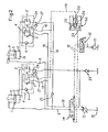
- Fig. 2 this differs from Fig. 1 in that the sequence valve 11, non-return valve 20 and orifice 21 are replaced by a hydraulic intensifier lla.
- advantage is taken of the pressure signal from the servo-hand controller 16 for remotely activating the selector valve 14 to cause lowering of the excavator boom by feeding this pressure signal from the appropriate line 15 into the input 24 of the hydraulic intensifier lla.
- the output signal from the hydraulic intensifier is fed at its output 25 to the pilot line 10 for the relief valve 7 of the load control valve 4.
- sufficient pilot pressure is obtained to give an acceptable boom lowering speed whilst using a low- pressure energy source.
- the pilot line 10 from the intensifier lla to the body of the load control valve 4 would normally be a closed line in which entrained air would not be flushed out. This could critically effect the operation of the relief valve 7 since, if sufficient in quantity, the amount of compression required would exceed the available displacement of the intensifier output piston 26.
- the circuit includes an automatic bleed system operative when boom lowering is not selected, to flush the pilot line 10 from the load control valve body and through the intensifier lla.
- This bleed system includes a non-return valve 27 and line 28 connected into the pilot port of the relief valve 7 and a non-return valve 29 in the intensifier lla which is unseated when the intensifier is inoperative, such that flow will be induced in the pilot line 10 from the relief valve to the intensifier, thus purging the lines and cavities within the relief valve pilot section and the intensifier.
- FIG. 3 the circuit of Figure 3 differs from that of Figure 1 in that the sequence valve 11, valve 20 and orifice 21 are omitted and a venting valve 30 is incorporated in a pilot line 31 connected to a port 32 in the relief valve 7 and to the servo-hand controller 16 and one of the lines 15.
- the load-control valve 4 consists of the relief valve 7 and non-return valve 6 which are independent of each other but which are contained within a common valve body 33.
- the relief valve 7 has a hollow-cylindrical valve plunger 34 which is slidingly and sealingly mounted within the valve body 33, the annular seals 35 dividing the valve body into four chambers 36, 37, 38 and 39 which are connected respectively through ports 40, 41, 42 and 32 to the raising side 19 of the ram cylinder 2, the raising feed line 18 to the selector valve 14, the pilot line 10 connected to the lowering feed line 8, and the pilot line 31 to the vent valve 30.
- the left-hand end of the valve plunger 34 is normally biased into a position in which it engages a valve seat 43 on the valve body 33 by means of a compression spring 44 in the valve chamber 39 and acting between the opposite end of the valve body and valve plunger.
- balancingholes 47 are provided through the plunger 34 to feed this pressure into the spring chamber 39 and thus balance the effects of back pressure on the plunger.
- the balancing holes 47 must be carefully selected to ensure that the venting valve 30 may be quite small. This valve 30 is set to ensure that only when the servo signal to the selector valve 14 has reached a certain level, predetermined by tests, will the valve 30 open to vent the spring chamber 39 and thus fully open the relief valve 7.
- the non-return valve 6 comprises a valve plunger 47a which is urged into engagement at one of its ends with a mating seat 48 on the valve body 33 by a spring 49 disposed in a chamber 50. Passages 51, and 52 in the valve body communicate with the port 40 to the raising side of the ram cylinder 2, with the spring chamber 50 and an annular chamber 53 adjacent the valve seat 48 respectively.
- pump flow through port 41 is connected to raising feed line 18 and the interior of valve plunger 34 causes the valve plunger 47a to be moved to the left as illustrated in Fig. 4 disengaging the latter from its seat and opening the valve 6 against the spring pressure so that flow passes through valve chamber 48 and passage 52 to port 40. Any hose burst in the feed raising line 18 will result in the valve plunger 47a immediately re-engaging the seat 48 and thus closing the non-return valve 6.
Landscapes
- Engineering & Computer Science (AREA)
- Physics & Mathematics (AREA)
- Fluid Mechanics (AREA)
- Mechanical Engineering (AREA)
- General Engineering & Computer Science (AREA)
- Fluid-Pressure Circuits (AREA)
Applications Claiming Priority (2)
| Application Number | Priority Date | Filing Date | Title |
|---|---|---|---|
| GB8110699 | 1981-04-06 | ||
| GB8110699 | 1981-04-06 |
Publications (1)
| Publication Number | Publication Date |
|---|---|
| EP0063025A1 true EP0063025A1 (de) | 1982-10-20 |
Family
ID=10520960
Family Applications (1)
| Application Number | Title | Priority Date | Filing Date |
|---|---|---|---|
| EP82301825A Withdrawn EP0063025A1 (de) | 1981-04-06 | 1982-04-06 | Hydraulischer Steuerkreis für einen Hydraulikzylinder |
Country Status (1)
| Country | Link |
|---|---|
| EP (1) | EP0063025A1 (de) |
Cited By (6)
| Publication number | Priority date | Publication date | Assignee | Title |
|---|---|---|---|---|
| FR2541735A1 (fr) * | 1983-02-25 | 1984-08-31 | Same Spa | Circuit hydraulique d'alimentation d'actionneur |
| US5191826A (en) * | 1990-07-05 | 1993-03-09 | Heilmeier & Weinlein Fabrik Fur Oel-Hydraulik | Hydraulic control device |
| US6422804B1 (en) * | 2000-02-18 | 2002-07-23 | Deere & Company | Inertia load dampening hydraulic system |
| DE102008053061A1 (de) * | 2008-10-24 | 2010-04-29 | Hydac System Gmbh | Hydromechanische Abstützeinrichtung |
| EP2739128B1 (de) | 2011-08-05 | 2016-07-20 | Precision Planting LLC | Vorrichtungen, systeme und verfahren zur schardrucksteuerung von reiheneinheiten |
| CN112483500A (zh) * | 2020-12-11 | 2021-03-12 | 河北新铁虎石油机械有限公司 | 一种带压作业机升降油缸液压控制系统 |
Citations (5)
| Publication number | Priority date | Publication date | Assignee | Title |
|---|---|---|---|---|
| GB929481A (en) * | 1961-04-03 | 1963-06-26 | New York Air Brake Co | Hydraulic mechanism |
| DE1550452A1 (de) * | 1966-06-15 | 1969-08-21 | Martin Presch | Gesteuertes Hydraulik-Rueckschlagventil |
| DE1600970A1 (de) * | 1967-02-25 | 1970-06-18 | Berlin Spezialfahrzeugwerk | Rohrbruch- und Halteventil mit Ruecklaufdrossel |
| DE2424973A1 (de) * | 1974-05-22 | 1975-12-04 | Montan Hydraulik Gmbh & Co Kg | Einrichtung zum steuern von hydroantrieben |
| US3943825A (en) * | 1972-04-17 | 1976-03-16 | Caterpillar Tractor Co. | Hydraulic control system for load supporting hydraulic motors |
-
1982
- 1982-04-06 EP EP82301825A patent/EP0063025A1/de not_active Withdrawn
Patent Citations (5)
| Publication number | Priority date | Publication date | Assignee | Title |
|---|---|---|---|---|
| GB929481A (en) * | 1961-04-03 | 1963-06-26 | New York Air Brake Co | Hydraulic mechanism |
| DE1550452A1 (de) * | 1966-06-15 | 1969-08-21 | Martin Presch | Gesteuertes Hydraulik-Rueckschlagventil |
| DE1600970A1 (de) * | 1967-02-25 | 1970-06-18 | Berlin Spezialfahrzeugwerk | Rohrbruch- und Halteventil mit Ruecklaufdrossel |
| US3943825A (en) * | 1972-04-17 | 1976-03-16 | Caterpillar Tractor Co. | Hydraulic control system for load supporting hydraulic motors |
| DE2424973A1 (de) * | 1974-05-22 | 1975-12-04 | Montan Hydraulik Gmbh & Co Kg | Einrichtung zum steuern von hydroantrieben |
Cited By (11)
| Publication number | Priority date | Publication date | Assignee | Title |
|---|---|---|---|---|
| FR2541735A1 (fr) * | 1983-02-25 | 1984-08-31 | Same Spa | Circuit hydraulique d'alimentation d'actionneur |
| US5191826A (en) * | 1990-07-05 | 1993-03-09 | Heilmeier & Weinlein Fabrik Fur Oel-Hydraulik | Hydraulic control device |
| US6422804B1 (en) * | 2000-02-18 | 2002-07-23 | Deere & Company | Inertia load dampening hydraulic system |
| DE102008053061A1 (de) * | 2008-10-24 | 2010-04-29 | Hydac System Gmbh | Hydromechanische Abstützeinrichtung |
| EP2739128B1 (de) | 2011-08-05 | 2016-07-20 | Precision Planting LLC | Vorrichtungen, systeme und verfahren zur schardrucksteuerung von reiheneinheiten |
| US9955623B2 (en) | 2011-08-05 | 2018-05-01 | Precision Planting Llc | Apparatus, systems and methods for row unit downforce control |
| US10238023B2 (en) | 2011-08-05 | 2019-03-26 | Precision Planting Llc | Apparatus, systems and methods for row unit downforce control |
| EP3106012B1 (de) | 2011-08-05 | 2019-12-11 | Precision Planting LLC | Pflanzmaschine mit eine vielzahl an reiheneinheiten, systeme und verfahren zur abtriebssteuerung von reiheneinheiten |
| US10834863B2 (en) | 2011-08-05 | 2020-11-17 | Precision Planting Llc | Apparatus, systems and methods for row unit downforce control |
| EP3106012B2 (de) † | 2011-08-05 | 2023-10-11 | Precision Planting LLC | Landwirtschaftliche pflanzmaschine mit einer vielzahl an reiheneinheiten und mit einem system zur schardrucksteuerung der reiheneinheiten |
| CN112483500A (zh) * | 2020-12-11 | 2021-03-12 | 河北新铁虎石油机械有限公司 | 一种带压作业机升降油缸液压控制系统 |
Similar Documents
| Publication | Publication Date | Title |
|---|---|---|
| JP3298623B2 (ja) | 非シャトル圧力補償器付液圧制御バルブ装置 | |
| JP3150980B2 (ja) | 圧力補償液圧制御装置 | |
| US4004607A (en) | Conduit arrangement with protection against rupture and leakage | |
| US7104181B2 (en) | Hydraulic control circuit for a hydraulic lifting cylinder | |
| JP4856131B2 (ja) | 作業機械の油圧システム | |
| US3563137A (en) | Hydraulic self-leveling control for boom and bucket | |
| US7121189B2 (en) | Electronically and hydraulically-actuated drain value | |
| CN101166904B (zh) | 具有压力补偿器的液压系统 | |
| US6241212B1 (en) | Hose rupture control valve unit | |
| US3868821A (en) | Automatic pump control system | |
| KR100631067B1 (ko) | 홀딩밸브의 응답성이 개선된 유압제어밸브 | |
| US3906840A (en) | Hydraulic control system for load supporting hydraulic motors | |
| US7258058B2 (en) | Metering valve with integral relief and makeup function | |
| US4006667A (en) | Hydraulic control system for load supporting hydraulic motors | |
| KR100490479B1 (ko) | 굴삭기용 홀딩밸브장치 및 홀딩밸브의 유압제어방법 | |
| JP3182152B2 (ja) | 流体流失状態での制御を維持できる液圧バルブ | |
| US3805678A (en) | Hydraulic control system for load supporting hydraulic motors | |
| US5136930A (en) | Apparatus for supplying pressure oil to hydraulic cylinders employed in working machines | |
| JP2923050B2 (ja) | 急速下降弁 | |
| US4286502A (en) | Hydraulic load lifting system with automatic blocking valve | |
| US5081839A (en) | Pressure compensated hydraulic system | |
| JPH11230375A (ja) | 再生回路を有する方向制御弁 | |
| JPH0343484B2 (de) | ||
| JPH05202903A (ja) | 液圧駆動システム | |
| US4320691A (en) | Hydraulic load lifting system with hydraulic surcharge to make up valve pilot lines |
Legal Events
| Date | Code | Title | Description |
|---|---|---|---|
| PUAI | Public reference made under article 153(3) epc to a published international application that has entered the european phase |
Free format text: ORIGINAL CODE: 0009012 |
|
| AK | Designated contracting states |
Designated state(s): DE FR GB |
|
| 17P | Request for examination filed |
Effective date: 19830309 |
|
| STAA | Information on the status of an ep patent application or granted ep patent |
Free format text: STATUS: THE APPLICATION IS DEEMED TO BE WITHDRAWN |
|
| 18D | Application deemed to be withdrawn |
Effective date: 19841101 |
|
| RIN1 | Information on inventor provided before grant (corrected) |
Inventor name: APPLEWHITE, PHILLIP |