EP0063055B1 - Stromwender für flachen Motor und Verfahren zur Herstellung desselben - Google Patents
Stromwender für flachen Motor und Verfahren zur Herstellung desselben Download PDFInfo
- Publication number
- EP0063055B1 EP0063055B1 EP82301928A EP82301928A EP0063055B1 EP 0063055 B1 EP0063055 B1 EP 0063055B1 EP 82301928 A EP82301928 A EP 82301928A EP 82301928 A EP82301928 A EP 82301928A EP 0063055 B1 EP0063055 B1 EP 0063055B1
- Authority
- EP
- European Patent Office
- Prior art keywords
- slits
- commutator
- segments
- insulating member
- connection
- Prior art date
- Legal status (The legal status is an assumption and is not a legal conclusion. Google has not performed a legal analysis and makes no representation as to the accuracy of the status listed.)
- Expired
Links
- 238000004519 manufacturing process Methods 0.000 title claims description 12
- 238000000034 method Methods 0.000 claims description 9
- 238000004804 winding Methods 0.000 claims description 9
- 239000004020 conductor Substances 0.000 claims description 7
- 239000011810 insulating material Substances 0.000 claims description 5
- 238000000465 moulding Methods 0.000 claims description 3
- 238000005452 bending Methods 0.000 claims description 2
- 238000005520 cutting process Methods 0.000 claims description 2
- 239000005011 phenolic resin Substances 0.000 claims description 2
- 238000004080 punching Methods 0.000 claims description 2
- 239000012774 insulation material Substances 0.000 claims 1
- 230000002787 reinforcement Effects 0.000 description 5
- 229920005989 resin Polymers 0.000 description 5
- 239000011347 resin Substances 0.000 description 5
- RYGMFSIKBFXOCR-UHFFFAOYSA-N Copper Chemical compound [Cu] RYGMFSIKBFXOCR-UHFFFAOYSA-N 0.000 description 4
- 229910052802 copper Inorganic materials 0.000 description 4
- 239000010949 copper Substances 0.000 description 4
- QGZKDVFQNNGYKY-UHFFFAOYSA-N Ammonia Chemical compound N QGZKDVFQNNGYKY-UHFFFAOYSA-N 0.000 description 2
- 229910000881 Cu alloy Inorganic materials 0.000 description 2
- 108091092889 HOTTIP Proteins 0.000 description 2
- 210000003298 dental enamel Anatomy 0.000 description 2
- 238000009413 insulation Methods 0.000 description 2
- KXGFMDJXCMQABM-UHFFFAOYSA-N 2-methoxy-6-methylphenol Chemical compound [CH]OC1=CC=CC([CH])=C1O KXGFMDJXCMQABM-UHFFFAOYSA-N 0.000 description 1
- BQCADISMDOOEFD-UHFFFAOYSA-N Silver Chemical compound [Ag] BQCADISMDOOEFD-UHFFFAOYSA-N 0.000 description 1
- 239000000853 adhesive Substances 0.000 description 1
- 229910021529 ammonia Inorganic materials 0.000 description 1
- 239000011521 glass Substances 0.000 description 1
- 239000012212 insulator Substances 0.000 description 1
- 239000000463 material Substances 0.000 description 1
- 229920001568 phenolic resin Polymers 0.000 description 1
- 239000000843 powder Substances 0.000 description 1
- 229910052709 silver Inorganic materials 0.000 description 1
- 239000004332 silver Substances 0.000 description 1
- 238000005476 soldering Methods 0.000 description 1
- 229920003002 synthetic resin Polymers 0.000 description 1
- 239000000057 synthetic resin Substances 0.000 description 1
Images
Classifications
-
- H—ELECTRICITY
- H02—GENERATION; CONVERSION OR DISTRIBUTION OF ELECTRIC POWER
- H02K—DYNAMO-ELECTRIC MACHINES
- H02K13/00—Structural associations of current collectors with motors or generators, e.g. brush mounting plates or connections to windings; Disposition of current collectors in motors or generators; Arrangements for improving commutation
- H02K13/04—Connections between commutator segments and windings
-
- H—ELECTRICITY
- H01—ELECTRIC ELEMENTS
- H01R—ELECTRICALLY-CONDUCTIVE CONNECTIONS; STRUCTURAL ASSOCIATIONS OF A PLURALITY OF MUTUALLY-INSULATED ELECTRICAL CONNECTING ELEMENTS; COUPLING DEVICES; CURRENT COLLECTORS
- H01R39/00—Rotary current collectors, distributors or interrupters
- H01R39/02—Details for dynamo electric machines
- H01R39/04—Commutators
- H01R39/06—Commutators other than with external cylindrical contact surface, e.g. flat commutators
-
- H—ELECTRICITY
- H02—GENERATION; CONVERSION OR DISTRIBUTION OF ELECTRIC POWER
- H02K—DYNAMO-ELECTRIC MACHINES
- H02K23/00—DC commutator motors or generators having mechanical commutator; Universal AC/DC commutator motors
- H02K23/54—Disc armature motors or generators
-
- H—ELECTRICITY
- H01—ELECTRIC ELEMENTS
- H01R—ELECTRICALLY-CONDUCTIVE CONNECTIONS; STRUCTURAL ASSOCIATIONS OF A PLURALITY OF MUTUALLY-INSULATED ELECTRICAL CONNECTING ELEMENTS; COUPLING DEVICES; CURRENT COLLECTORS
- H01R39/00—Rotary current collectors, distributors or interrupters
- H01R39/02—Details for dynamo electric machines
- H01R39/32—Connections of conductor to commutator segment
-
- H—ELECTRICITY
- H01—ELECTRIC ELEMENTS
- H01R—ELECTRICALLY-CONDUCTIVE CONNECTIONS; STRUCTURAL ASSOCIATIONS OF A PLURALITY OF MUTUALLY-INSULATED ELECTRICAL CONNECTING ELEMENTS; COUPLING DEVICES; CURRENT COLLECTORS
- H01R43/00—Apparatus or processes specially adapted for manufacturing, assembling, maintaining, or repairing of line connectors or current collectors or for joining electric conductors
- H01R43/06—Manufacture of commutators
-
- Y—GENERAL TAGGING OF NEW TECHNOLOGICAL DEVELOPMENTS; GENERAL TAGGING OF CROSS-SECTIONAL TECHNOLOGIES SPANNING OVER SEVERAL SECTIONS OF THE IPC; TECHNICAL SUBJECTS COVERED BY FORMER USPC CROSS-REFERENCE ART COLLECTIONS [XRACs] AND DIGESTS
- Y10—TECHNICAL SUBJECTS COVERED BY FORMER USPC
- Y10T—TECHNICAL SUBJECTS COVERED BY FORMER US CLASSIFICATION
- Y10T29/00—Metal working
- Y10T29/49—Method of mechanical manufacture
- Y10T29/49002—Electrical device making
- Y10T29/49009—Dynamoelectric machine
- Y10T29/49011—Commutator or slip ring assembly
Definitions
- This invention relates to a commutator for a flat electric motor and its manufacturing process, and more particularly to a commutator for a flat motor having a disc-shaped wound armature, arranged to facilitate connection of the armature winding to the commutator.
- the invention also relates to the manufacture of such a commutator.
- Afurtherexample of a commutator of this type is described as one of the embodiments in GB-A-2 013 415.
- the commutator there described consists of an annular member of non-conducting resin having spaced metallic commuatator segments on one face; each of these segments includes, at its outer edge, a connector pin which extends axially through the annular member and projects from the far side. At its inner edge, each segment includes a bent portion which is anchored in the resin. Electrical connections are made with the segments via the connector pins.
- the manufacture of this commutator is as follows: an electrically-conducting flat sheet is first stamped into a suitable blank, comprising an annular shape having inwardly-pointing fingerlike extensions and outwardly-pointing fingerlike extensions.
- Both of these extensions are then bent until they lie at 90° to the plane of the annulus, and the resin is moulded around the resulting shape so that it is bonded to one side of the sheet with the inner extensions embedded in the resin and the outer ones (the pins) passing through it. Finally, the sheet is cut radially into individual commutator segments.
- this type of fiat commutator shows not only a difficulty in its manufacture; but a restriction on the area which may be occupied by the armature to be formed at the outside of the tab, due to the fact that the tab is formed at an outer edge end of the brush contact piece.
- a requirement for making a large effective area of the fan causes some limitations to the diameter of the flat motor. Due to this, it is necessary to position the tab as close as possible to the rotary axis and make a wide distance between an outer diameter of the armature and the tab in order to make a large area for the armature. Since the output of the motor is related to the area of armature, said distance should be increased.
- the present invention provides a commutator for a flat electric motor including a plurality of segments made of conductive material arranged in an annular pattern and having sector-shaped brush-contact pieces, and connection pieces raised up from the brush contact pieces and electrically connected therewith, the segments being insulated from each other by an insulating member, and characterised in that the connection pieces are positioned at the inner edges of the segments, and the top ends of the connection pieces are bent to an inverted U-shape, their free ends are buried in the insulating member, slits being made atthetop ends of said connection pieces and being adapted to receive connection wires of an armature winding so as to connect the segments with the respective armature windings.
- the invention provides a process for manufacturing a commutator for a flat motor comprising and characterised by the steps of: punching out a central part of a top-hat shaped member of conductive material having a flange part at a lower portion thereof, bending the top part of the hat-shaped member inwardly and downwardly so as to form an annular projection of inverted U-shape cross-section; making slits in a spaced apart relation in said annular projection from its top end down to the surface of the flange so as to form an odd number of connection pieces separated by the slits; moulding an insulating member around the top hat-shaped member, leaving the bottom surface of the flange and the annular projection exposed while burying the free edge of the annular projection into the insulating member, the member extending into said slits; cutting further slits in the flange part of said moulded member in a radial pattern corresponding to said slits so as to form a
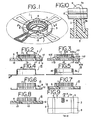
- segments 4 which constitute a commutator 1 are provided with a fan-shaped brush contact piece 2 and a connector piece 3 raised up from the brush contact piece 2 and electrically integral therewith, the segment being formed of a superior conductive material such as copper or copper alloy etc.
- the segments 4 are constructed such that an upper end 3a of the connector piece 3 is bent over to form an inverted U-shape, the arms of the U being parallel.
- a plurality of segments 4 are arranged spaced apart in an annular pattern in such a way that the connector pieces 3 are positioned at their inner edges.
- a plurality of segments 4 arranged in such annular pattern are moulded in a resin insulating member 5 which is itself of annular form.
- each segment 4 is formed with a bent part 12 for use in preventing slip or movement of the segment relative to the insulating member.
- the inverted U-shaped bent edge 3b is buried in the insulating material 5. That part of the insulating material lying within the U-shaped bent portion is moulded integrally with the rest of the moulded member 5. It is possible to fix a reinforcement member (not shown) of copper or copper alloy to this bent portion.
- Some slits 6 are cut in said U-shaped bent top end 3a.
- a left half section corresponds in position to the slits 11, 13 formed between the segments 4.
- Figure 3 illustrates another embodiment of the present invention in which a bent end 103b buried in the insulating member 105 is further bent inwards thereinto.
- a reference numeral increased by 100 corresponds to the same component element as that shown in Figure 2.
- a sheet of good conductive material for example a copper sheet having a silver content of 0.03 wt%
- a sheet of good conductive material for example a copper sheet having a silver content of 0.03 wt%
- a top hat-like member 15 having a hole 14 at its central part and a flange part 9 at its lower portion, as shown in Figure 4.
- the central hole 14 is drawn inwardly to form a bent part 3b, thereby an annular projection having its top end 3a showing an inverted U-shape cross-section is formed.
- the width of the space 16 at the bent portion is substantially the same as, for example, that of the copper sheet.
- annular reinforcement member or another type of annular reinforcement member coated with a conductive adhesive agent Into the space 16 formed by the bent part 3b is, if required, press fitted an annular reinforcement member or another type of annular reinforcement member coated with a conductive adhesive agent. In this condition, some slits 11 are cut, as shown in Figure 6, down to the flange 9 in a spaced apart relation, thus an odd number of connector pieces 3 are formed. Portions corresponding to slits 13 at the circumference of the flange 9 (to be described later) are partially cut out and then the remained non-cut portions are bent upwardly. Thus, said comb-like hat-shaped member 15 forms a continuous body which is connected only at the flange.
- the annular reinforcement member When the annular reinforcement member is included this also has the slits 11 cut therein and the reinforcement member is thus divided in the same way as the connector pieces 3. Further, as shown in Figure 7, the hat-shaped member 15 having said slits 11 is received into the moulded synthetic resin insulating member 5, which may be formed of, for example, FUDOWLITE F5760F (ammonia free phenolic resin with glass powder made by Fudow Chemical Co., Ltd.) with a bottom surface of the flange 9 being exposed. The insulator member extends into said slits 11, and each of the connector pieces 3 is insulated from each other.
- the moulded synthetic resin insulating member 5 which may be formed of, for example, FUDOWLITE F5760F (ammonia free phenolic resin with glass powder made by Fudow Chemical Co., Ltd.) with a bottom surface of the flange 9 being exposed.
- the insulator member extends into said slits 11, and each of the connector pieces 3 is insulated from
- a plurality of slits 13 are cut in a radial pattern in the flange 9, in correspondence with said slits 11, deeper than a thickness of said flange 9, thereby a plurality of fan-shaped divided contact pieces 2 are formed separated from each other. Surfaces of the contact pieces 2 become a brush sliding contact surface 17.
- slits 6 for a wire connection are cut at the top end 3a in the bent part of the connector piece 3 so as to form a commutator 1.
- connection wires (enamel coated wires) 8 and the commutator 1 are heated by a hot tip heated up to a desired temperature, the connection wires 8 are pushed into the slits 6 by the hot tip, and at the same time the wires are further heated by their energisation, finally a thermal press fitting is performed.
- This hot stake process enables a breakage of insulation by applying thermal energy, and also enables both electrical and mechanical connections even if the insulation of the connected wires (enamel coated wires) is peeled off.
- a top errd of the connector piece is bent to form an inverted U-shape and buried into the material of the insulating member, so that the strength of the commutator may be improved and it becomes possible to tie the connection wires to the commutator by applying so-called hot-stake process, and a fast rigid connection between the commutator and the' armature winding may be performed.
- the connector piece has a fixed width irrespective of a fan-shape form of the segment, so that the strength of the commutator may substantially be improved.
- the segments are not assembled after manufacture but an integrally formed hat-shaped member is bent, some slits are cut in the member so as to form the connection pieces, then the insulating material is moulded therein, and the flange is cut to make the segments.
- the manufacture may thus be performed in a quite simple manner.
- the connector pieces are formed at the points nearest to the rotary axis, so it is possible to keep a wide distance from an outer edge of said armature to the connector piece even if an outer diameter of the armature is the same of that of a conventional one and therefore the area of the armature may be increased.
Landscapes
- Engineering & Computer Science (AREA)
- Power Engineering (AREA)
- Motor Or Generator Current Collectors (AREA)
- Manufacture Of Motors, Generators (AREA)
Claims (7)
Applications Claiming Priority (2)
| Application Number | Priority Date | Filing Date | Title |
|---|---|---|---|
| JP56055134A JPS57170048A (en) | 1981-04-14 | 1981-04-14 | Commutator for flat motor |
| JP55134/81 | 1981-04-14 |
Publications (3)
| Publication Number | Publication Date |
|---|---|
| EP0063055A2 EP0063055A2 (de) | 1982-10-20 |
| EP0063055A3 EP0063055A3 (en) | 1983-03-30 |
| EP0063055B1 true EP0063055B1 (de) | 1986-08-06 |
Family
ID=12990304
Family Applications (1)
| Application Number | Title | Priority Date | Filing Date |
|---|---|---|---|
| EP82301928A Expired EP0063055B1 (de) | 1981-04-14 | 1982-04-14 | Stromwender für flachen Motor und Verfahren zur Herstellung desselben |
Country Status (4)
| Country | Link |
|---|---|
| US (2) | US4453102A (de) |
| EP (1) | EP0063055B1 (de) |
| JP (1) | JPS57170048A (de) |
| DE (1) | DE3272429D1 (de) |
Families Citing this family (7)
| Publication number | Priority date | Publication date | Assignee | Title |
|---|---|---|---|---|
| GB2218861B (en) * | 1988-05-17 | 1992-04-22 | Gen Motors France | Alternator with cylindrical and flat slip-rings |
| US5189329A (en) * | 1988-09-26 | 1993-02-23 | Johnson Electric S.A. | Assembled commutator |
| DE4002254A1 (de) * | 1990-01-26 | 1991-08-14 | Licentia Gmbh | Ultraschallmotor mit zwei rotoren |
| JP3313508B2 (ja) * | 1994-04-25 | 2002-08-12 | 株式会社ミツバ | コミテータ |
| US5793140A (en) * | 1995-12-19 | 1998-08-11 | Walbro Corporation | Electric motor flat commutator |
| US5925962A (en) * | 1995-12-19 | 1999-07-20 | Walbro Corporation | Electric motor commutator |
| RU2153213C1 (ru) * | 1999-02-15 | 2000-07-20 | Открытое акционерное общество "Завод имени А.М. Тарасова" | Способ изготовления торцового коллектора |
Family Cites Families (16)
| Publication number | Priority date | Publication date | Assignee | Title |
|---|---|---|---|---|
| US1592326A (en) * | 1924-08-14 | 1926-07-13 | Westinghouse Electric & Mfg Co | Commutator |
| BE343077A (de) * | 1926-07-22 | |||
| DE1284512B (de) * | 1966-09-01 | 1968-12-05 | Bosch Gmbh Robert | Verfahren zur Herstellung eines Plankommutators fuer elektrische Maschinen |
| JPS4524183Y1 (de) * | 1967-03-31 | 1970-09-22 | ||
| US3524251A (en) * | 1968-04-08 | 1970-08-18 | Circuit Res Co | Method of manufacturing disc-type wire wound electrical machines |
| US3519863A (en) * | 1969-01-02 | 1970-07-07 | Stanley Works | Commutator lead mounting |
| DE2034502A1 (de) * | 1970-07-11 | 1972-01-27 | Bosch Gmbh Robert | Kommutator fur elektrische Maschinen |
| SU396773A1 (ru) * | 1971-03-29 | 1973-08-29 | Торцовый коллектор электрической машины | |
| US3681027A (en) * | 1971-05-28 | 1972-08-01 | Resource Control | Colorimetric indicator for the detection of nitrogen dioxide |
| JPS5227801B2 (de) * | 1971-10-25 | 1977-07-22 | ||
| GB1438960A (en) * | 1972-11-23 | 1976-06-09 | Lucas Electrical Ltd | Method of manufacturing a rotor assembly for a dynamo electric machine optical transmission systems |
| DE7309667U (de) * | 1973-03-14 | 1976-04-08 | Robert Bosch Gmbh, 7000 Stuttgart | Trommeiförmiger Kommutator für umlaufende elektrische Maschinen |
| FR2295589A1 (fr) * | 1974-12-20 | 1976-07-16 | Sev Marchal | Bague a pistes collectrices pour machine electrique tournante et machine correspondante |
| FR2400269A1 (fr) * | 1977-08-10 | 1979-03-09 | Sev Marchal | Bague a deux pistes collectrices fixee sans serrage sur un arbre de machine electrique tournante et machine correspondante |
| US4283841A (en) * | 1978-01-26 | 1981-08-18 | Mitsuba Electric Mfg. Co., Ltd. | Method of manufacturing a commutator |
| JPS56159959A (en) * | 1980-05-13 | 1981-12-09 | Nippon Radiator Co Ltd | Manufacture of armature for flat motor |
-
1981
- 1981-04-14 JP JP56055134A patent/JPS57170048A/ja active Pending
-
1982
- 1982-04-14 US US06/368,501 patent/US4453102A/en not_active Expired - Fee Related
- 1982-04-14 DE DE8282301928T patent/DE3272429D1/de not_active Expired
- 1982-04-14 EP EP82301928A patent/EP0063055B1/de not_active Expired
-
1984
- 1984-02-27 US US06/583,774 patent/US4523374A/en not_active Expired - Fee Related
Also Published As
| Publication number | Publication date |
|---|---|
| US4453102A (en) | 1984-06-05 |
| EP0063055A2 (de) | 1982-10-20 |
| DE3272429D1 (en) | 1986-09-11 |
| JPS57170048A (en) | 1982-10-20 |
| US4523374A (en) | 1985-06-18 |
| EP0063055A3 (en) | 1983-03-30 |
Similar Documents
| Publication | Publication Date | Title |
|---|---|---|
| US3785049A (en) | Slip ring assembly and method of making same | |
| US6160337A (en) | Electric motor with carbon track commutator | |
| US3538365A (en) | Commutator having disc-shaped base | |
| JP3622118B2 (ja) | スリップリングユニット | |
| US20120313478A1 (en) | Commutator | |
| EP0905861B1 (de) | Endpol eines Drehmelders | |
| CA1250884A (en) | Connection of tapered armature conductor to tapered commutator slot | |
| US6445103B2 (en) | Commutators for electric motors and method of manufacturing same | |
| EP0063055A2 (de) | Stromwender für flachen Motor und Verfahren zur Herstellung desselben | |
| JP3468809B2 (ja) | 電気機械に用いられるドラム形コレクタ | |
| US4930210A (en) | Method for assembling an electric motor armature | |
| US7485998B2 (en) | Commutator | |
| US4490637A (en) | Electrical machine with multi disc commutator | |
| EP0271175B1 (de) | Kommutator | |
| US6189769B1 (en) | Method of cable wire arrangement | |
| US1592326A (en) | Commutator | |
| EP1237235B1 (de) | Ebener Kohlesegmentkommutator | |
| US3522462A (en) | Commutator winding connectors | |
| GB2035683A (en) | A temperature sensor | |
| US2176361A (en) | Radial commutator | |
| EP0632934B1 (de) | Verfahren und Vorrichtung zur Herstellung eines Ankers | |
| JPS5883554A (ja) | フラツトモ−タ用コンミユテ−タおよびその製造方法 | |
| JP2000125517A (ja) | コミテータおよびその製造方法 | |
| EP0379664A1 (de) | Kommutator für elektrische Maschinen | |
| JP2002136060A (ja) | 円筒型整流子及びその製造方法 |
Legal Events
| Date | Code | Title | Description |
|---|---|---|---|
| PUAI | Public reference made under article 153(3) epc to a published international application that has entered the european phase |
Free format text: ORIGINAL CODE: 0009012 |
|
| AK | Designated contracting states |
Designated state(s): DE FR GB |
|
| PUAL | Search report despatched |
Free format text: ORIGINAL CODE: 0009013 |
|
| AK | Designated contracting states |
Designated state(s): DE FR GB |
|
| 17P | Request for examination filed |
Effective date: 19830419 |
|
| GRAA | (expected) grant |
Free format text: ORIGINAL CODE: 0009210 |
|
| AK | Designated contracting states |
Kind code of ref document: B1 Designated state(s): DE FR GB |
|
| REF | Corresponds to: |
Ref document number: 3272429 Country of ref document: DE Date of ref document: 19860911 |
|
| ET | Fr: translation filed | ||
| PLBE | No opposition filed within time limit |
Free format text: ORIGINAL CODE: 0009261 |
|
| STAA | Information on the status of an ep patent application or granted ep patent |
Free format text: STATUS: NO OPPOSITION FILED WITHIN TIME LIMIT |
|
| 26N | No opposition filed | ||
| PGFP | Annual fee paid to national office [announced via postgrant information from national office to epo] |
Ref country code: GB Payment date: 19900404 Year of fee payment: 9 |
|
| PGFP | Annual fee paid to national office [announced via postgrant information from national office to epo] |
Ref country code: FR Payment date: 19900415 Year of fee payment: 9 |
|
| PGFP | Annual fee paid to national office [announced via postgrant information from national office to epo] |
Ref country code: DE Payment date: 19900531 Year of fee payment: 9 |
|
| PG25 | Lapsed in a contracting state [announced via postgrant information from national office to epo] |
Ref country code: GB Effective date: 19910414 |
|
| GBPC | Gb: european patent ceased through non-payment of renewal fee | ||
| PG25 | Lapsed in a contracting state [announced via postgrant information from national office to epo] |
Ref country code: FR Effective date: 19911230 |
|
| PG25 | Lapsed in a contracting state [announced via postgrant information from national office to epo] |
Ref country code: DE Effective date: 19920201 |
|
| REG | Reference to a national code |
Ref country code: FR Ref legal event code: ST |