EP0063081A1 - Montagevorrichtung für einen verstellbaren Fahrzeugsitz - Google Patents
Montagevorrichtung für einen verstellbaren Fahrzeugsitz Download PDFInfo
- Publication number
- EP0063081A1 EP0063081A1 EP82400620A EP82400620A EP0063081A1 EP 0063081 A1 EP0063081 A1 EP 0063081A1 EP 82400620 A EP82400620 A EP 82400620A EP 82400620 A EP82400620 A EP 82400620A EP 0063081 A1 EP0063081 A1 EP 0063081A1
- Authority
- EP
- European Patent Office
- Prior art keywords
- roller
- seat
- support
- rollers
- rack
- Prior art date
- Legal status (The legal status is an assumption and is not a legal conclusion. Google has not performed a legal analysis and makes no representation as to the accuracy of the status listed.)
- Granted
Links
- 125000006850 spacer group Chemical group 0.000 claims description 13
- 239000003831 antifriction material Substances 0.000 claims description 2
- 230000000284 resting effect Effects 0.000 claims description 2
- 244000309466 calf Species 0.000 description 1
- 210000000080 chela (arthropods) Anatomy 0.000 description 1
- 230000000694 effects Effects 0.000 description 1
- 230000003100 immobilizing effect Effects 0.000 description 1
- 230000002093 peripheral effect Effects 0.000 description 1
- 238000005096 rolling process Methods 0.000 description 1
- 238000005728 strengthening Methods 0.000 description 1
Images


Classifications
-
- B—PERFORMING OPERATIONS; TRANSPORTING
- B60—VEHICLES IN GENERAL
- B60N—SEATS SPECIALLY ADAPTED FOR VEHICLES; VEHICLE PASSENGER ACCOMMODATION NOT OTHERWISE PROVIDED FOR
- B60N2/00—Seats specially adapted for vehicles; Arrangement or mounting of seats in vehicles
- B60N2/02—Seats specially adapted for vehicles; Arrangement or mounting of seats in vehicles the seat or part thereof being movable, e.g. adjustable
- B60N2/04—Seats specially adapted for vehicles; Arrangement or mounting of seats in vehicles the seat or part thereof being movable, e.g. adjustable the whole seat being movable
- B60N2/06—Seats specially adapted for vehicles; Arrangement or mounting of seats in vehicles the seat or part thereof being movable, e.g. adjustable the whole seat being movable slidable
Definitions
- the position of the seats of motor vehicles is, in general, adjustable longitudinally. To this end, the seats have so far been mounted directly or with the aid of intermediate parts on the vehicle floor via ball bearing slides. These slides are heavy, fragile and expensive. In addition, they do not contribute in any way to strengthening the transverse rigidity of the body structure.
- the present invention relates to a device for mounting a vehicle seat which avoids the use of a slide and, moreover, transversely reinforces the passenger compartment at the level of the seat line, so that the bodywork resists particularly well the effects of the forces developed during a side impact and that the pilot and the passenger are protected in an area where safety is essential.
- the device according to the invention is characterized in that it comprises two parallel transverse spacers released from the floor, connected at each of their ends to the side members of the bodywork and on which rollers are axially immobilized, in that the seat is integral .
- de bearing tracks based on at least some of the rollers which thus constitute support rollers, and at least one rack disposed longitudinally
- the said p-o operative part comprises in addition, on the one hand a toothed means cooperating with the rack and making it possible to immobilize the latter and on the other hand at least two bridges which are integral with the seat and each of which embraces one of the spacers while maintaining the tracks support on the support rollers, bridges or certain support tracks comprising a rib engaged in a groove of the corresponding roller or vice versa, this roller thus constituting a guide roller.
- the spacers thus play a double role: they reinforce the structure of the bodywork and support the seat.
- the rack When the rack is released, it is possible to adjust the longitudinal position of the seat, within the limit permitted by the bridges, the support tracks having a translational movement on the rollers.
- the bridges hold the seat on the crosspieces and thus prevent it from inadvertently separating from the crosspieces, for example to tilt forwards in the event of a frontal impact.
- one of the rollers has a toothed part engaged with the rack which thus forms a support track and means are provided for immobilizing the roller in rotation.
- the rack cannot move and the seat is locked in position.
- the device comprises a handle which is pivotally mounted on the front cross member and comprises a clean toothed part. To come into engagement with the rack under the action of elastic means. When this toothed part is engaged with the rack, the seat is immobilized. On the other hand, it is possible to move it if the handle is tilted so as to disengage its toothed part from the rack.
- the guide roller cooperating with the trigger guard can be a roller in contact with a support track, it thus constitutes both a guide roller and a support roller. But, in this case, the roller caught in pincers between the support track and the trigger guard, rolls on the trigger guard in the opposite direction to the direction of movement on this trigger guard, so that there is friction. To reduce the latter, it is possible to provide the rib of the roller or the trigger guard with a track in an anti-friction material, preferably flexible and slightly compressed.
- the guide roller cooperating with the trigger guard may also not cooperate with the support tracks, that is to say not be a support roller.
- the roller cleared tracks then rolls without friction on the trigger guard, pivoting in the opposite direction to the direction of rotation of the rollers cooperating with the support tracks.
- one of the crosspieces carries a guide and stop roller arranged substantially in the longitudinal median plane of the seat while the other crosspiece carries two guide rollers arranged in the vicinity of the lateral edges from the headquarters.
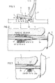
- each of the bridges is articulated by one of its ends at 6 on the base 2; its other end is fixed to this base by a locking hook 7 which is articulated at 8 on the trigger guard and can engage in a spout 9 fixed to the base.
- a roller 1 ( is rotatably mounted on the front spacer 3a, substantially in the longitudinal median plane of the seat.
- This roller has a central groove 11 in which is engaged a rectilinear median projection 12 provided under the base 2.
- the roller 11 is cut into pinions 13a and 13b which are not taken with racks 14a and 14b fixed under the base 2.
- a single trigger guard 5a which is located opposite the projection 12.
- This trigger guard carries a central projection 15 which is provided with a friction track 16 engaged in the groove 11.
- the rear cross member 3b carries, in the vicinity of each of the lateral edges of the seat l, a roller 23 which can pivot freely on this downpour.
- This roller has a smooth periphery but comprises, like the roller 10, a central groove 11 'in which is engaged a straight projection 12' provided under the base 2.
- This roller is immobilized laterally by two stops 24a and 24b fixed on the crosspiece 3b .
- these bridges 12b comp.or tent a median projection 15 which is provided with a friction track 16 engaged in the groove 11 'of the corresponding roller 23.
- the roller 10 In normal times, the roller 10 is immobilized and the seat cannot move longitudinally. However, if the plate 20 is removed from the roller 10, by means not shown in the drawing, the roller 10 is released and can pivot. The seat can move longitudinally by resting on the front roller 11 and on the rear rollers 23. During this movement, the seat is guided by the racks 13a and 13b and by the projections 12 and 12 'engaged in the grooves 11 and 11 ' shingles. If the plate 20 is released, the tabs 19 engage in the cavities 18 and immobilize again calf the roller 10 on the spacer 3a, the seat thus being locked in its new position. It can be seen that it is therefore possible to adjust the longitudinal position of the seat at will, within the limits authorized by the bridges 5a and 5b.
- the roller 10 is replaced by a set of two rollers 25 and 26, both mounted for rotation on the crosspiece.
- the roller 25 which guides the seat is not toothed and has a central groove 27 in which is engaged the projection 15 of the trigger guard 5a, this projection being here constituted by a stamping of the trigger guard.
- the roller 26 is toothed and engaged with the rack 14 which forms the support track.
- this roller carries on one of its sides cavities 18 into which the tocs19 of the plate 20 can engage.
- the two rollers 25 and 26 pivot in opposite directions, the roller 25 rolling without friction on the projection 15. If desired, one can provide a second toothed roller on the other side of the roller 25.
- the roller 23 is replaced by an assembly comprising a central roller 28 and two lateral ga-lets 29.
- the central roller 28 has a central groove 30 in which the projection is engaged 15 of the trigger guard 5b, the latter being disposed in the longitudinal median plane of the base 2.
- Each of the lateral rollers 29 also comprises a central groove 31 in which one of the projections 12 ′ of the base 2 is engaged.
- Each of these rollers is immobilized laterally by two stops 24a and 24b, fixed on the crosspiece.
- the rollers 28 and 29 can pivot in the opposite direction so that they roll without friction on the projections on which they are engaged.
- the toothed roller 10 still replaced by a smooth roller 25.
- a handle 32 which is mounted on the spacer 5a and carries a toothing 33 which can engage, under the action of springs 34, in a rack provided under the base 2.
- this rack does not form a support track for the seat, the seat comprises a rib 12 engaged in groove 27 of the roller 25.
- the guide rollers could comprise not grooves, but peripheral ribs engaged in grooves of the support tracks and bridges.
Landscapes
- Engineering & Computer Science (AREA)
- Aviation & Aerospace Engineering (AREA)
- Transportation (AREA)
- Mechanical Engineering (AREA)
- Seats For Vehicles (AREA)
Applications Claiming Priority (2)
| Application Number | Priority Date | Filing Date | Title |
|---|---|---|---|
| FR8107314A FR2503062A1 (fr) | 1981-04-07 | 1981-04-07 | Montage de siege de vehicule |
| FR8107314 | 1981-04-07 |
Publications (2)
| Publication Number | Publication Date |
|---|---|
| EP0063081A1 true EP0063081A1 (de) | 1982-10-20 |
| EP0063081B1 EP0063081B1 (de) | 1985-07-17 |
Family
ID=9257294
Family Applications (1)
| Application Number | Title | Priority Date | Filing Date |
|---|---|---|---|
| EP19820400620 Expired EP0063081B1 (de) | 1981-04-07 | 1982-04-05 | Montagevorrichtung für einen verstellbaren Fahrzeugsitz |
Country Status (3)
| Country | Link |
|---|---|
| EP (1) | EP0063081B1 (de) |
| DE (1) | DE3264746D1 (de) |
| FR (1) | FR2503062A1 (de) |
Citations (5)
| Publication number | Priority date | Publication date | Assignee | Title |
|---|---|---|---|---|
| FR889640A (fr) * | 1942-09-07 | 1944-01-14 | Tubauto | Siège, notamment banquette pour camions, autocars et autres véhicules |
| DE1037878B (de) * | 1954-12-15 | 1958-08-28 | Keiper Fa F | Sitz fuer Fahrzeuge, insbesondere Personenkraftwagen |
| FR2243838A1 (de) * | 1973-09-14 | 1975-04-11 | Saito Takeji | |
| FR2419839A1 (fr) * | 1978-03-15 | 1979-10-12 | Tubauto | Dispositif de maintien d'un siege sur le plancher d'un vehicule |
| EP0028564A1 (de) * | 1979-11-05 | 1981-05-13 | Societe Industrielle Bertrand Faure | Fahrzeugsitz mit zumindest einer Sitzschale |
-
1981
- 1981-04-07 FR FR8107314A patent/FR2503062A1/fr active Granted
-
1982
- 1982-04-05 DE DE8282400620T patent/DE3264746D1/de not_active Expired
- 1982-04-05 EP EP19820400620 patent/EP0063081B1/de not_active Expired
Patent Citations (5)
| Publication number | Priority date | Publication date | Assignee | Title |
|---|---|---|---|---|
| FR889640A (fr) * | 1942-09-07 | 1944-01-14 | Tubauto | Siège, notamment banquette pour camions, autocars et autres véhicules |
| DE1037878B (de) * | 1954-12-15 | 1958-08-28 | Keiper Fa F | Sitz fuer Fahrzeuge, insbesondere Personenkraftwagen |
| FR2243838A1 (de) * | 1973-09-14 | 1975-04-11 | Saito Takeji | |
| FR2419839A1 (fr) * | 1978-03-15 | 1979-10-12 | Tubauto | Dispositif de maintien d'un siege sur le plancher d'un vehicule |
| EP0028564A1 (de) * | 1979-11-05 | 1981-05-13 | Societe Industrielle Bertrand Faure | Fahrzeugsitz mit zumindest einer Sitzschale |
Also Published As
| Publication number | Publication date |
|---|---|
| EP0063081B1 (de) | 1985-07-17 |
| FR2503062B1 (de) | 1983-05-20 |
| FR2503062A1 (fr) | 1982-10-08 |
| DE3264746D1 (en) | 1985-08-22 |
Similar Documents
| Publication | Publication Date | Title |
|---|---|---|
| EP0888926B1 (de) | Fahrzeugsitz mit einer Halsschutzvorrichtung bei einem Heckaufprall | |
| EP0947380B1 (de) | Auf dem Schienenboden eingebaute Zahnstangenvorrichtung | |
| FR2864481A1 (fr) | Agencement pour le montage d'un siege sur le plancher d'un vehicule au moyen de plots de guidage escamotables | |
| FR2707938A1 (fr) | Porte-bagages pour véhicule automobile. | |
| FR2796822A1 (fr) | Appuie-tete perfectionne et siege muni de cet appuie-tete | |
| FR2645810A1 (fr) | Dispositif d'amenagement des sieges dans un vehicule, notamment utilitaire | |
| FR2963586A1 (fr) | Glissiere pour siege de vehicule automobile a verrouillage lateral sans jeu | |
| FR2777049A1 (fr) | Systeme d'arrimage modulable a commande par cames | |
| EP0800952B1 (de) | Kraftfahrzeugsitz, nach vorn bewegbar, um zu einem Hinterraum Zugang zu haben | |
| FR2634699A1 (en) | Device forming a seat slideway | |
| EP3789246B1 (de) | Vorrichtung zum verstauen mit schubladen für ein kraftfahrzeug | |
| FR2679179A1 (fr) | Glissiere pour siege de vehicule comportant un dispositif de reduction des jeux et d'elimination des bruits. | |
| EP1190893A2 (de) | Mehrfach positionierbare Kopfstütze und Sitz mit einer solchen Kopfstütze | |
| FR2689825A1 (fr) | Appui-tête pour siège de véhicule automobile. | |
| EP0063081B1 (de) | Montagevorrichtung für einen verstellbaren Fahrzeugsitz | |
| FR3041577A1 (fr) | Mecanisme de verrouillage, ensemble interieur de vehicule et vehicule correspondant | |
| EP0543706B1 (de) | Vorrichtung zum automatischen Kuppeln einer Sicherheitsgurtverankerung mit dem Boden eines Fahrzeuges | |
| EP0296939A1 (de) | Vordere Mittelarmlehne mit zwei stabilen Lagen für Kraftfahrzeuge | |
| EP0192006B1 (de) | Kraftfahrzeugsitz | |
| EP1808330A2 (de) | Sitz für Kraftfahrzeug, der entlang einer ersten Achse x und einer zweiten Achse y beweglich ist, und Kraftfahrzeug, das einen solchen Sitz umfasst | |
| EP1619070B1 (de) | Führungsvorrichtung für eine bewegliche Einheit | |
| FR2795028A1 (fr) | Siege pour vehicule | |
| FR2545426A1 (fr) | Dispositif de reglage d'inclinaison du coussin d'un siege de vehicule automobile | |
| FR2879980A1 (fr) | Dispositif de console amovible coulissante pour vehicule automobile et vehicule automobile equipe d'un tel dispositif | |
| FR3160656A1 (fr) | Dispositif d’accrochage de boucle de ceinture de sécurité |
Legal Events
| Date | Code | Title | Description |
|---|---|---|---|
| PUAI | Public reference made under article 153(3) epc to a published international application that has entered the european phase |
Free format text: ORIGINAL CODE: 0009012 |
|
| AK | Designated contracting states |
Designated state(s): DE GB IT |
|
| 17P | Request for examination filed |
Effective date: 19821025 |
|
| ITF | It: translation for a ep patent filed | ||
| GRAA | (expected) grant |
Free format text: ORIGINAL CODE: 0009210 |
|
| AK | Designated contracting states |
Designated state(s): DE GB IT |
|
| REF | Corresponds to: |
Ref document number: 3264746 Country of ref document: DE Date of ref document: 19850822 |
|
| ITPR | It: changes in ownership of a european patent |
Owner name: OFFERTA DI LICENZA AL PUBBLICO |
|
| PLBE | No opposition filed within time limit |
Free format text: ORIGINAL CODE: 0009261 |
|
| STAA | Information on the status of an ep patent application or granted ep patent |
Free format text: STATUS: NO OPPOSITION FILED WITHIN TIME LIMIT |
|
| 26N | No opposition filed | ||
| PGFP | Annual fee paid to national office [announced via postgrant information from national office to epo] |
Ref country code: GB Payment date: 19900331 Year of fee payment: 9 |
|
| PGFP | Annual fee paid to national office [announced via postgrant information from national office to epo] |
Ref country code: DE Payment date: 19900522 Year of fee payment: 9 |
|
| PG25 | Lapsed in a contracting state [announced via postgrant information from national office to epo] |
Ref country code: GB Effective date: 19910405 |
|
| GBPC | Gb: european patent ceased through non-payment of renewal fee | ||
| PG25 | Lapsed in a contracting state [announced via postgrant information from national office to epo] |
Ref country code: DE Effective date: 19920201 |