EP0063191B1 - System zum Verhindern des Überlaufens bei Tankschiffen - Google Patents
System zum Verhindern des Überlaufens bei Tankschiffen Download PDFInfo
- Publication number
- EP0063191B1 EP0063191B1 EP81301781A EP81301781A EP0063191B1 EP 0063191 B1 EP0063191 B1 EP 0063191B1 EP 81301781 A EP81301781 A EP 81301781A EP 81301781 A EP81301781 A EP 81301781A EP 0063191 B1 EP0063191 B1 EP 0063191B1
- Authority
- EP
- European Patent Office
- Prior art keywords
- vessel
- trunk line
- coupled
- line means
- petroleum products
- Prior art date
- Legal status (The legal status is an assumption and is not a legal conclusion. Google has not performed a legal analysis and makes no representation as to the accuracy of the status listed.)
- Expired
Links
- 230000002265 prevention Effects 0.000 title abstract description 8
- 230000014759 maintenance of location Effects 0.000 claims abstract description 45
- 239000000126 substance Substances 0.000 claims abstract description 41
- 239000012530 fluid Substances 0.000 claims abstract description 39
- 239000003209 petroleum derivative Substances 0.000 claims abstract description 39
- 238000012354 overpressurization Methods 0.000 claims abstract description 8
- 239000007789 gas Substances 0.000 claims description 17
- 238000013022 venting Methods 0.000 claims description 9
- XLYOFNOQVPJJNP-UHFFFAOYSA-N water Substances O XLYOFNOQVPJJNP-UHFFFAOYSA-N 0.000 claims description 6
- 239000007788 liquid Substances 0.000 claims description 4
- 239000010779 crude oil Substances 0.000 description 3
- -1 for example Substances 0.000 description 3
- 239000004215 Carbon black (E152) Substances 0.000 description 2
- 238000010276 construction Methods 0.000 description 2
- 230000001419 dependent effect Effects 0.000 description 2
- 229930195733 hydrocarbon Natural products 0.000 description 2
- 150000002430 hydrocarbons Chemical class 0.000 description 2
- 239000003921 oil Substances 0.000 description 2
- 238000005086 pumping Methods 0.000 description 2
- 238000011109 contamination Methods 0.000 description 1
- 238000003912 environmental pollution Methods 0.000 description 1
- 238000004880 explosion Methods 0.000 description 1
- 239000011521 glass Substances 0.000 description 1
- 230000007257 malfunction Effects 0.000 description 1
- 238000012986 modification Methods 0.000 description 1
- 230000004048 modification Effects 0.000 description 1
- 230000000717 retained effect Effects 0.000 description 1
- 238000004513 sizing Methods 0.000 description 1
- 239000011800 void material Substances 0.000 description 1
Images

Classifications
-
- B—PERFORMING OPERATIONS; TRANSPORTING
- B63—SHIPS OR OTHER WATERBORNE VESSELS; RELATED EQUIPMENT
- B63B—SHIPS OR OTHER WATERBORNE VESSELS; EQUIPMENT FOR SHIPPING
- B63B25/00—Load-accommodating arrangements, e.g. stowing, trimming; Vessels characterised thereby
- B63B25/02—Load-accommodating arrangements, e.g. stowing, trimming; Vessels characterised thereby for bulk goods
- B63B25/08—Load-accommodating arrangements, e.g. stowing, trimming; Vessels characterised thereby for bulk goods fluid
- B63B25/10—Load-accommodating arrangements, e.g. stowing, trimming; Vessels characterised thereby for bulk goods fluid open to ambient air
-
- B—PERFORMING OPERATIONS; TRANSPORTING
- B63—SHIPS OR OTHER WATERBORNE VESSELS; RELATED EQUIPMENT
- B63J—AUXILIARIES ON VESSELS
- B63J2/00—Arrangements of ventilation, heating, cooling, or air-conditioning
- B63J2/02—Ventilation; Air-conditioning
- B63J2/08—Ventilation; Air-conditioning of holds
Definitions
- the present invention relates to an automatic system for preventing external cargo spillage from tanker vessels resulting from the overflow of cargo from the cargo compartments of the vessel during loading thereof.
- cargo comprising fluid chemical and petroleum products, such as, for example, oil
- transfer hoses and cargo pipelines which are coupled to inlets communicative with the cargo compartments of the vessel. It sometimes occurs during loading or transfer of cargo that the fluid and chemical products continue to flow after the compartments are full.
- cargo overflows through ullage openings, gas vents or other deck apertures communicative with the compartments, over the deck of the vessel and into the water, thereby causing a spill and producing water contamination, atmospheric pollution, as well as a fire and explosion hazard.
- Cargo spills are the result of a variety of causes.
- One, for example, is negligence on the part of personnel in charge of loading the cargo compartments of the vessel.
- Another is a faulty loading valve, for example, a leaky valve or a foreign substance wedged under the valve gate.
- Others are a leaking line under pressure within the cargo compartments; an increase, without notice, of the vessel loading rate; and a broken valve reach rod or other control segment during closing of an inlet valve after a cargo compartment has been filled.
- Such cargo overflows can cause significant pollution of coastal waterways, particularly when the cargo being loaded is crude oil. For example, depending upon the size of the vessel and the flow rate of the cargo during loading and the duration of the overflow before it is discovered, anywhere from several barrels to several thousand barrels of oil may be lost from a single cargo spill caused by an overflow.
- Cargo tank overfill control systems have been devised to prevent overflows from cargo compartments of a tanker vessel during loading.
- High level alarms and continuous tank cargo level indicators are used to monitor cargo tank levels in a vessel during loading. While such devices are helpful, they are subject to malfunctions, are dependent on human monitors, and do not automatically prevent pollution, and these characteristics make such devices unacceptable for vessels carrying cargoes such as crude oil having the potential of creating serious environmental pollution in coastal waterways and ports in the event of spillage from the vessel caused by an overflow during loading.
- U.S.-A-3628559 discloses a spillage prevention system for use on a cargo tanker in which the cargo tanks include expansion trunks and a main conduit runs fore and aft in the vessel with a plurality of lateral conduits connected to the main conduit and opening into the expansion trunks respectively whereby overflow from any of the tanks passes into the associated one of the lateral conduits and then into the main conduit for discharge into an empty cargo space.
- the invention provides a tanker vessel for the transportation of fluid chemical and petroleum products in water, which vessel includes a hull comprising a bottom and sides, a top deck a plurality of liquid-tight cargo compartments disposed within the hull between the top deck and the hull bottom for receiving the fluid chemical/ petroleum products, means coupled to said cargo compartments for filling said compartments with said fluid chemical/petroleum products, longitudinally disposed trunk line means, branch line means coupled at one end to said trunk line means and at the other end to said cargo compartments, valve means coupled to said branch line means intermediate the ends thereof, for permitting the free flow of fluid chemical and petroleum products from said cargo compartments to said trunk line means through said branch line means, and retention tank means disposed in said vessel and coupled to said trunk line means for receiving fluid chemical/petroleum products from said tank line means, characterised in that said branch line means are dimensioned so as to prevent over-pressurization of said cargo compartments during the flow of said fluid chemical/petroleum products from said compartments to said trunk line means, in that said
- the invention also provides a tanker vessel for the transportation of fluid chemical/petroleum products in water, which vessel includes a hull comprising a bottom and sides, a top deck, a plurality of liquid-tight cargo compartments disposed within the hull between the top deck and the hull bottom for receiving the fluid chemical/ petroleum products, and means coupled to said cargo compartments for filling said compartments with said fluid chemical/petroleum products, longitudinally disposed trunk line means, branch line means coupled at one end to said trunk line means and at the other end to said cargo compartments, valve means coupled to said branch line means intermediate the ends thereof, for permitting the free flow of fluid chemical/petroleum products from said cargo compartments to said trunk line means through said branch line means, and retention tank means disposed in said vessel and coupled to said trunk line means for receiving fluid chemical/petroleum products from said trunk line means, characterised in that said branch line means are dimensioned so as to prevent over pressurization of said cargo compartments during the flow of said fluid chemical/petroleum products from the compartments to
- the improved spill overflow system of the present invention will significantly reduce safety hazards, cargo loss, and the pollution of coastal waterways and ports caused by tank overflows during loading operations, transfers, discharge or cargo expansion in a tanker vessel. This is achieved by utilizing a retention tank, specifically one or more empty tanks, such as a cofferdam, void space or ballast tank or other suitable vessel space, as a plenum, and directing any overflows from the cargo compartments into such a retention tank.
- a retention tank specifically one or more empty tanks, such as a cofferdam, void space or ballast tank or other suitable vessel space, as a plenum
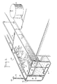
- a tanker vessel generally identified by the reference numeral 10 which includes a hull comprising a bottom 11 and sides 12, a top or a main deck 13, and a plurality of watertight cargo compartments 14.
- the cargo compartments are disposed within the hull between top deck 13 and hull bottom 11 for receiving cargo comprising fluid chemical and petroleum products, for example, crude oil, from a land storage tank 15.
- Cargo expansion trunks 16 are coupled to and open downwardly into each of cargo compartments 14.
- a cargo pipeline 17 is coupled to each of the cargo compartments 14 for filling the compartments with cargo from land storage tank 15.
- Vessel 10 includes a longitudinal trunk line 18, which can be disposed either above or below top deck 13, and a plurality of branch lines 19 which are coupled at one end to trunk line 18 and at the 'other end to cargo expansion trunks 16.
- a plurality of valves 20, which may comprise either non-return clapper valves, weighted or spring- controlled to produce the required back pressure for vapor venting, or positive type closure valves, the latter preferably being butterfly-type valves, are coupled to the branch lines 19 intermediate the ends thereof for permitting the free flow of fluid chemical and petroleum products, i.e., the liquid cargo, from cargo expansion trunks 16 to trunk line 18 through branch lines 19.
- a cargo retention tank 21 which may comprise either a wing tank or a plurality of interconnected tanks of the vessel, is coupled to trunk line 18 for receiving cargo from the trunk line.
- An overflow pipe 22 is disposed within the retention tank 21 for directing the cargo overflow within the retention tank and has an enlarged opening 23 at one end thereof which is disposed below the end of trunk line 18. The latter extends downwardly and opens into the retention tank 21 just below top deck 13.
- the enlarged opening 23 of pipe 22 receives cargo overflow from trunk line 18 and is spaced slightly apart from the end of the trunk line in tank 21 in order to permit gases, for example, hydrocarbon gases and the like to escape from the trunk line into the retention tank 21.
- a plurality of apertures may also be disposed about the periphery of opening 23 to permit gases to escape into retention tank 21.
- the retention tank is provided with an exhaust vent 24 which includes a flame screen 25 and a pressure/ vacuum relief valve 26 for venting gases from the retention tank to the atmosphere. Gases are vented from the cargo compartments 14 to the atmosphere during filling of the compartments through trunk line 18 and branch lines 19 to retention tank 21.
- a plurality of bypass lines 27 are coupled to branch lines 19 intermediate the ends thereof and in parallel relationship therewith, each including a pressure/vacuum relief valve 28, which preferably comprises a closed type pressure/vacuum relief valve, coupled to the bypass line intermediate its ends, for venting gases from cargo compartments 14 to retention tank 21 through trunk line 18 and branch lines 19 when valves 20 are positive type closure valves and are closed, i.e., during all operations on the vessel except when filling any cargo compartments or transferring cargo between the compartments.
- valves 20 comprise non-return clapper valves
- the bypass lines 27 and valves 28 permit vacuum relief in the cargo compartments 14. It should be noted that the bypass lines 27 are not required if the vessel is retrofitted with the spill overflow prevention system of the invention and already has an existing venting system which is retained.
- Branch lines 19 are dimensioned, i.e., have a diameter which is large enough to prevent over- pressurization of the cargo compartments during an overflow while loading or transferring cargo.
- overpressurization means a pressure build-up in the cargo compartments due to the pumping of cargo into the compartments at high pressure which would cause structural damage to the bulkheads of the vessel.
- Such a pressure build-up is relieved by sizing the branch lines 19 so that the lines have a diameter which is greater than the diameter of the filling lines or pipes used to load the compartments to such an extent that the pressure in the cargo compartments is reduced to a level below the maximum the vessel bulkheads can withstand before sustaining damage.
- trunk line 18 and branch lines 19 may comprise rectangular or square-shaped ducts, or partially circular pipes, as well as the circular pipes illustrated in the drawings, and can be disposed either above or below the deck of the vessel.
- the diameter of trunk line 18, as a general rule, will always be considerably greater than that of the branch lines 19 and for that reason usually is not a factor in over- pressurization of the cargo compartments 14. If, however, for some reason a back pressure were produced by the trunk line, for example, if the trunk line had a diameter which was less than that of the branch lines, this pressure would have to be considered along with the pressure produced by the branch lines in determining the dimensions of the lines which will keep the pressure in the compartments 14 below the maximum allowable overpressure.
- a line flow alarm 29 is coupled in series with trunk line 18 for indicating the flow of cargo in the trunk line.
- retention tank 21 preferably comprises a side compartment of vessel 10 in order to provide an additional indication of the flow of cargo through the trunk line and of an overflow by causing the vessel to heel over slightly. This provides an additional level of protection in the event that the line flow alarm fails to indicate and/or crewmen working on the vessel are inattentive or are not present and fail to detect an overflow from the compartments through the trunk line.
- valves 20 comprise positive-type closure valves, the valves are opened prior to commencement of the loading operation. If non-return clapper valves are used, the valves will automatically open when an overflow occurs.
- the flow through the trunk line 18 is indicated by the flow alarm 29, which produces an audible and/or visible alarm.
- Cargo entering the retention tank is received by enlarged opening 23 of overflow pipe 22 and is directed by the pipe within the tank to the tank bottom.
- Gases present in cargo compartments 14, for example, hydrocarbon gases produced by petroleum products, are expelled from the compartments during loading or cargo transfer and flow through branch lines 19 into trunk line 18 and escape from the end of the trunk line in retention tank 21. The gases are then vented under pressure to the atmosphere through exhaust vent 24.
- the exhaust vent 24 is preferably designed so that it terminates at its open upper end at a level above the vessel's deck which is well clear of personnel areas and any hazard of ignition on the vessel.
- a closed tank loading system is required during loading or transfer operations on the vessel. This can be either an automatic or manual closed ullage system or a simple glass visor having an internal wiper device fitted in each ullage opening.
- the spill overflow system of the present invention may also be used for bunker tanks, chemical tanks, etc., to prevent overflow loss and hazard in the same manner as with cargo compartments.
Landscapes
- Chemical & Material Sciences (AREA)
- Engineering & Computer Science (AREA)
- Combustion & Propulsion (AREA)
- Mechanical Engineering (AREA)
- Ocean & Marine Engineering (AREA)
- Filling Or Discharging Of Gas Storage Vessels (AREA)
- Loading And Unloading Of Fuel Tanks Or Ships (AREA)
- Vibration Prevention Devices (AREA)
- Pipeline Systems (AREA)
Claims (10)
Priority Applications (3)
| Application Number | Priority Date | Filing Date | Title |
|---|---|---|---|
| EP81301781A EP0063191B1 (de) | 1981-04-22 | 1981-04-22 | System zum Verhindern des Überlaufens bei Tankschiffen |
| AT81301781T ATE15014T1 (de) | 1981-04-22 | 1981-04-22 | System zum verhindern des ueberlaufens bei tankschiffen. |
| DE8181301781T DE3171889D1 (en) | 1981-04-22 | 1981-04-22 | Spill overflow prevention system for tanker vessels |
Applications Claiming Priority (1)
| Application Number | Priority Date | Filing Date | Title |
|---|---|---|---|
| EP81301781A EP0063191B1 (de) | 1981-04-22 | 1981-04-22 | System zum Verhindern des Überlaufens bei Tankschiffen |
Publications (2)
| Publication Number | Publication Date |
|---|---|
| EP0063191A1 EP0063191A1 (de) | 1982-10-27 |
| EP0063191B1 true EP0063191B1 (de) | 1985-08-21 |
Family
ID=8188282
Family Applications (1)
| Application Number | Title | Priority Date | Filing Date |
|---|---|---|---|
| EP81301781A Expired EP0063191B1 (de) | 1981-04-22 | 1981-04-22 | System zum Verhindern des Überlaufens bei Tankschiffen |
Country Status (3)
| Country | Link |
|---|---|
| EP (1) | EP0063191B1 (de) |
| AT (1) | ATE15014T1 (de) |
| DE (1) | DE3171889D1 (de) |
Families Citing this family (2)
| Publication number | Priority date | Publication date | Assignee | Title |
|---|---|---|---|---|
| GB2382070A (en) * | 2001-11-20 | 2003-05-21 | Carl Denby | Refilling liquid storage tanks |
| GB2402931A (en) * | 2003-05-01 | 2004-12-22 | Carl Denby | A method of refilling liquid storage tanks to prevent overfilling |
Family Cites Families (3)
| Publication number | Priority date | Publication date | Assignee | Title |
|---|---|---|---|---|
| US3628559A (en) * | 1970-10-16 | 1971-12-21 | Mariani Branko | Ullage opening spillage prevention system |
| FR2331493A1 (fr) * | 1975-11-13 | 1977-06-10 | Handelmaatschappi Maschf | Dispositif d'aeration de citerne, notamment pour cargo |
| US4233922A (en) * | 1979-02-09 | 1980-11-18 | Conway Charles S | Fluid transfer system for tanker vessels |
-
1981
- 1981-04-22 EP EP81301781A patent/EP0063191B1/de not_active Expired
- 1981-04-22 DE DE8181301781T patent/DE3171889D1/de not_active Expired
- 1981-04-22 AT AT81301781T patent/ATE15014T1/de not_active IP Right Cessation
Also Published As
| Publication number | Publication date |
|---|---|
| DE3171889D1 (en) | 1985-09-26 |
| ATE15014T1 (de) | 1985-09-15 |
| EP0063191A1 (de) | 1982-10-27 |
Similar Documents
| Publication | Publication Date | Title |
|---|---|---|
| US4292909A (en) | Spill overflow prevention system for tanker vessels | |
| US4233922A (en) | Fluid transfer system for tanker vessels | |
| US5038960A (en) | Flexible liner system for tankers | |
| US5092259A (en) | Inert gas control in a system to reduce spillage of oil due to rupture of ship's tank | |
| US9453583B1 (en) | Vent for tank | |
| US4409919A (en) | Ship's double bottom and bag segregated ballast system | |
| US4058148A (en) | Vapor hose hookup assurance | |
| US5795103A (en) | Oil tanker and method for recovering oil from submerged oil tanker | |
| US2928436A (en) | Vapor sealed liquid carriers | |
| US6929039B2 (en) | Marine vessel fuel overflow tank system | |
| GB2040233A (en) | Improved method and apparatus for venting hydrocarbon gases from the cargo compartments of a tanker vessel | |
| US4723682A (en) | Floating roof tanks for liquids, in particular to storage tanks used in the nuclear power industry | |
| US3073333A (en) | Tight fill system for tank loading and discharging | |
| EP0063191A1 (de) | System zum Verhindern des Überlaufens bei Tankschiffen | |
| NO164825B (no) | Anordning for haandtering av ballastvann. | |
| JPH03208792A (ja) | 損傷したタンカからの石油漏れを制御する装置及び方法 | |
| US5042582A (en) | Horizontal heater/treater and/or vapor tight oil battery | |
| IE50874B1 (en) | Spill overflow prevention system for tanker vessels | |
| CA1136495A (en) | Spill overflow prevention system for tanker vessels | |
| US3840056A (en) | Apparatus for filling liquid storage tanks | |
| RU2287442C1 (ru) | Автомобильная заправочная станция с технологической системой "поле" | |
| MXPA00003743A (es) | Metodo y aparato para drenar tubos de conexion entre cisternas. | |
| KR850000139Y1 (ko) | 유조선에 있어서 기름이 넘쳐 흐르는 것을 방지하기 위한 장치 | |
| GB2026859A (en) | Method and apparatus for storing a volatile liquid | |
| US5156109A (en) | System to reduce spillage of oil due to rupture of ship's tank |
Legal Events
| Date | Code | Title | Description |
|---|---|---|---|
| PUAI | Public reference made under article 153(3) epc to a published international application that has entered the european phase |
Free format text: ORIGINAL CODE: 0009012 |
|
| AK | Designated contracting states |
Designated state(s): AT BE CH DE FR GB IT LU NL SE |
|
| 17P | Request for examination filed |
Effective date: 19821215 |
|
| ITF | It: translation for a ep patent filed | ||
| GRAA | (expected) grant |
Free format text: ORIGINAL CODE: 0009210 |
|
| AK | Designated contracting states |
Designated state(s): AT BE CH DE FR GB IT LI LU NL SE |
|
| PG25 | Lapsed in a contracting state [announced via postgrant information from national office to epo] |
Ref country code: LI Effective date: 19850821 Ref country code: CH Effective date: 19850821 Ref country code: BE Effective date: 19850821 Ref country code: AT Effective date: 19850821 |
|
| REF | Corresponds to: |
Ref document number: 15014 Country of ref document: AT Date of ref document: 19850915 Kind code of ref document: T |
|
| REF | Corresponds to: |
Ref document number: 3171889 Country of ref document: DE Date of ref document: 19850926 |
|
| ET | Fr: translation filed | ||
| REG | Reference to a national code |
Ref country code: CH Ref legal event code: PL |
|
| PG25 | Lapsed in a contracting state [announced via postgrant information from national office to epo] |
Ref country code: LU Free format text: LAPSE BECAUSE OF NON-PAYMENT OF DUE FEES Effective date: 19860430 |
|
| PLBE | No opposition filed within time limit |
Free format text: ORIGINAL CODE: 0009261 |
|
| STAA | Information on the status of an ep patent application or granted ep patent |
Free format text: STATUS: NO OPPOSITION FILED WITHIN TIME LIMIT |
|
| 26N | No opposition filed | ||
| PGFP | Annual fee paid to national office [announced via postgrant information from national office to epo] |
Ref country code: NL Payment date: 19870430 Year of fee payment: 7 |
|
| PG25 | Lapsed in a contracting state [announced via postgrant information from national office to epo] |
Ref country code: GB Effective date: 19890422 |
|
| PG25 | Lapsed in a contracting state [announced via postgrant information from national office to epo] |
Ref country code: SE Effective date: 19890423 |
|
| PG25 | Lapsed in a contracting state [announced via postgrant information from national office to epo] |
Ref country code: NL Effective date: 19891101 |
|
| NLV4 | Nl: lapsed or anulled due to non-payment of the annual fee | ||
| GBPC | Gb: european patent ceased through non-payment of renewal fee | ||
| PG25 | Lapsed in a contracting state [announced via postgrant information from national office to epo] |
Ref country code: FR Free format text: LAPSE BECAUSE OF NON-PAYMENT OF DUE FEES Effective date: 19891228 |
|
| PG25 | Lapsed in a contracting state [announced via postgrant information from national office to epo] |
Ref country code: DE Effective date: 19900103 |
|
| REG | Reference to a national code |
Ref country code: FR Ref legal event code: ST |
|
| EUG | Se: european patent has lapsed |
Ref document number: 81301781.1 Effective date: 19900412 |