EP0063211B1 - Porte-bagages pour véhicules à deux roues - Google Patents
Porte-bagages pour véhicules à deux roues Download PDFInfo
- Publication number
- EP0063211B1 EP0063211B1 EP82100943A EP82100943A EP0063211B1 EP 0063211 B1 EP0063211 B1 EP 0063211B1 EP 82100943 A EP82100943 A EP 82100943A EP 82100943 A EP82100943 A EP 82100943A EP 0063211 B1 EP0063211 B1 EP 0063211B1
- Authority
- EP
- European Patent Office
- Prior art keywords
- mounting
- luggage carrier
- legs
- frame
- carrier according
- Prior art date
- Legal status (The legal status is an assumption and is not a legal conclusion. Google has not performed a legal analysis and makes no representation as to the accuracy of the status listed.)
- Expired
Links
Images

Classifications
-
- B—PERFORMING OPERATIONS; TRANSPORTING
- B62—LAND VEHICLES FOR TRAVELLING OTHERWISE THAN ON RAILS
- B62J—CYCLE SADDLES OR SEATS; AUXILIARY DEVICES OR ACCESSORIES SPECIALLY ADAPTED TO CYCLES AND NOT OTHERWISE PROVIDED FOR, e.g. ARTICLE CARRIERS OR CYCLE PROTECTORS
- B62J7/00—Luggage carriers
- B62J7/02—Luggage carriers characterised by the arrangement thereof on cycles
- B62J7/04—Luggage carriers characterised by the arrangement thereof on cycles arranged above or behind the rear wheel
-
- Y—GENERAL TAGGING OF NEW TECHNOLOGICAL DEVELOPMENTS; GENERAL TAGGING OF CROSS-SECTIONAL TECHNOLOGIES SPANNING OVER SEVERAL SECTIONS OF THE IPC; TECHNICAL SUBJECTS COVERED BY FORMER USPC CROSS-REFERENCE ART COLLECTIONS [XRACs] AND DIGESTS
- Y10—TECHNICAL SUBJECTS COVERED BY FORMER USPC
- Y10T—TECHNICAL SUBJECTS COVERED BY FORMER US CLASSIFICATION
- Y10T403/00—Joints and connections
- Y10T403/71—Rod side to plate or side
- Y10T403/7111—Shackle is integral with or independently attached to proximate side of plate or other side
-
- Y—GENERAL TAGGING OF NEW TECHNOLOGICAL DEVELOPMENTS; GENERAL TAGGING OF CROSS-SECTIONAL TECHNOLOGIES SPANNING OVER SEVERAL SECTIONS OF THE IPC; TECHNICAL SUBJECTS COVERED BY FORMER USPC CROSS-REFERENCE ART COLLECTIONS [XRACs] AND DIGESTS
- Y10—TECHNICAL SUBJECTS COVERED BY FORMER USPC
- Y10T—TECHNICAL SUBJECTS COVERED BY FORMER US CLASSIFICATION
- Y10T403/00—Joints and connections
- Y10T403/71—Rod side to plate or side
- Y10T403/7194—Crossed rods
Definitions
- the invention relates to a luggage rack for two-wheeled vehicles, with a frame to be fastened to the two-wheeled vehicle and containing the luggage support surface and consisting of longitudinal and transverse struts, to which at least one pair of legs serving as a support is articulated by means of plastic bearing parts which embrace the longitudinal struts on opposite sides of the frame these are injection molded and each have a bearing bore extending transversely to the longitudinal struts, in which the legs are mounted with a cylindrical crosspiece.
- the object of the invention is therefore to provide a luggage rack that is characterized by a particularly easy to manufacture stable storage of the legs on the frame, which requires less effort for the plastic injection mold with easier handling and a perfect shapely connection between the frame and the Thighs guaranteed.
- each bearing part has an insertion slot for the cross piece which is continuous with the bearing bore, and the bearing bore extends through a laterally projecting fastening projection which is integrally formed on the bearing part and onto which the cross piece with an enclosing one and the wall of the bearing bore on the cross piece in contact holding the clamping ring is placed captive.
- the bearing parts of this luggage rack are first molded onto the longitudinal struts without the legs, which results in a significant simplification and less danger of the injection mold.
- the subsequent assembly of the legs on the bearing parts is carried out in a few simple steps, the clamping ring ensuring a very stable and aesthetically appealing captive mounting of the legs in the bearing parts.
- the fastening attachment has a cylindrical outer surface, so that a cylindrical clamping ring can be used. It is advantageous if the fastening projection is arranged facing from the assigned longitudinal strut to the inside of the frame, so that the clamping ring comes to rest on the inside of the assigned longitudinal strut.
- the legs with the longitudinal struts can be articulated to their bearing parts lying essentially in one plane, which has the advantage that the legs run inside or immediately below the longitudinal struts of the frame, which is known from the above-mentioned known for injection molding reasons Embodiment of a luggage rack with integral parts directly molded onto the legs is complicated.
- the arrangement can be such that the clamping ring is designed with a sharp inner edge on its side facing the free end face of the fastening attachment.
- the fastening attachment can also carry on its outer surface a latching device which cooperates with the clamping ring in the form of a small collar or a small notch, which also serves the purpose of captively holding the clamping ring.
- the luggage rack can be designed either as a rear wheel or as a front wheel luggage rack. It can be provided with a pair of legs or with two pairs of legs, wherein the cross piece connecting the legs of a pair to one another can also simultaneously form a cross strut of the frame.
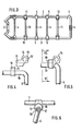
- the luggage carrier consists of a frame 1 which contains the luggage support surface and which is designed with a transverse link 2 with which it can be attached to the rear fork of a two-wheeled vehicle.
- the frame 1 is composed of two parallel longitudinal struts 3 interconnected on one side by the cross flap 2 and on the other side by an injection-molded plastic connecting part 4 and a number of cross struts 4 which are connected at the end to the longitudinal struts 3 by means of injection-molded plastic parts 5.
- a pair of legs 6 and 7 is articulated.
- the two pairs of legs 6, 7 are set up to be fastened at their free ends 8 and 9 to the extension of the two-wheeled vehicle frame, which is referred to as the dropout, by means of a clamp and a screw in a manner known per se in the vicinity of the wheel hub.
- the two legs of the pair of legs 6 and 7 are each connected to one another by an integrally formed cylindrical horizontal cross piece 10 and 11, which in the manner shown in FIG. 3 simultaneously forms a cross strut of the frame 1.
- the two legs of a pair of legs are separated from one another and are each essentially L-shaped in the case of the U-shaped shape of a pair of legs which results in this way together with the cross piece 10, or the cross pieces of this L-shaped Legs of a pair of legs are connected to each other by a molded plastic connecting part.
- the pair of legs 6 and 7 is pivotally mounted with its cylindrical cross piece 10 and 11 in two plastic bearing parts, the structure of which can be seen in particular from FIGS. 4 and 6, and which together with the plastic parts 4, 5 in one operation integrally molded onto the longitudinal struts 3, encompassing them.
- Each bearing part 12 has a part 13 encompassing the associated longitudinal strut 3, which forms part of the luggage support surface at the top at 14 and to which a fastening projection 15, which carries a cylindrical outer circumferential surface 16, is protruding on the side.
- a bearing bore 17 extends below the longitudinal strut 3 and transversely thereto through the fastening projection 15, into which an insertion slot 18 leads from the underside.
- a cylindrical clamping ring 19 is pushed onto the cylindrical outer surface 16 of the fastening projection 15, which is made of plastic material, but preferably of metal and here in particular aluminum.
- the clamping ring 19 is formed on its side facing the free end face 20 of the fastening projection 15 with a sharp inner edge which is somewhat pressed into the plastic material during the pretensioning of the clamping ring on the fastening projection 15 and therefore an unintentional detachment of the clamping ring 19 from the Fastening approach 15 excludes.
- this is provided on the inside on the opposite side with a chamfer indicated at 21.
- a locking device in the form of a small collar or a small indentation can also be provided on the attachment projection 15 as additional security, if necessary.
- a plastic material is used which has a certain inherent elasticity, which allows the aforementioned snapping of the cross piece 10 into the bearing bore 17.
- the longitudinal struts 3 and the cross struts 4 and the legs 6, 7 with their cross pieces 10, 11 are preferably made of aluminum.
- the legs of the pairs of legs 6, 7 can lie essentially in a common plane with the adjacent longitudinal struts 3. In any case, they do not protrude laterally beyond the outline of the bearing parts 12. This is important for both aesthetic and stability reasons.
Landscapes
- Engineering & Computer Science (AREA)
- Mechanical Engineering (AREA)
- Fittings On The Vehicle Exterior For Carrying Loads, And Devices For Holding Or Mounting Articles (AREA)
- Handcart (AREA)
- Rolling Contact Bearings (AREA)
- Automatic Cycles, And Cycles In General (AREA)
- Packaging Of Machine Parts And Wound Products (AREA)
- Packaging Of Annular Or Rod-Shaped Articles, Wearing Apparel, Cassettes, Or The Like (AREA)
- Packages (AREA)
- Bag Frames (AREA)
- Mutual Connection Of Rods And Tubes (AREA)
Claims (7)
Priority Applications (1)
| Application Number | Priority Date | Filing Date | Title |
|---|---|---|---|
| AT82100943T ATE11257T1 (de) | 1981-03-20 | 1982-02-10 | Gepaecktraeger fuer zweiradfahrzeuge. |
Applications Claiming Priority (2)
| Application Number | Priority Date | Filing Date | Title |
|---|---|---|---|
| DE3110870A DE3110870C2 (de) | 1981-03-20 | 1981-03-20 | Stützenbefestigung für Gepäckträger für Zweiradfahrzeuge |
| DE3110870 | 1981-03-20 |
Publications (2)
| Publication Number | Publication Date |
|---|---|
| EP0063211A1 EP0063211A1 (fr) | 1982-10-27 |
| EP0063211B1 true EP0063211B1 (fr) | 1985-01-16 |
Family
ID=6127787
Family Applications (1)
| Application Number | Title | Priority Date | Filing Date |
|---|---|---|---|
| EP82100943A Expired EP0063211B1 (fr) | 1981-03-20 | 1982-02-10 | Porte-bagages pour véhicules à deux roues |
Country Status (7)
| Country | Link |
|---|---|
| US (1) | US4408705A (fr) |
| EP (1) | EP0063211B1 (fr) |
| AT (1) | ATE11257T1 (fr) |
| DE (1) | DE3110870C2 (fr) |
| DK (1) | DK152105C (fr) |
| FI (1) | FI72473C (fr) |
| NO (1) | NO154626C (fr) |
Families Citing this family (3)
| Publication number | Priority date | Publication date | Assignee | Title |
|---|---|---|---|---|
| IT8134051U1 (it) * | 1981-11-19 | 1983-05-19 | F Lli Barro Giovanni & Luigi S R L | Portapacchi di tipo perfezionato particolarmente applicabile su biciclette. |
| DE3472653D1 (en) * | 1983-04-12 | 1988-08-18 | Esge Marby Gmbh & Co | Luggage carrier for two-wheeled vehicles |
| DE202009015485U1 (de) | 2009-11-09 | 2010-02-11 | Ahrens, Johannes | Lastenträger für ein Zweiradfahrzeug, insbesondere ein Fahrrad |
Family Cites Families (13)
| Publication number | Priority date | Publication date | Assignee | Title |
|---|---|---|---|---|
| GB394334A (en) * | 1931-12-21 | 1933-06-21 | Ernest Alfred Boom | Improvements in fasteners for loose leaf binders |
| GB460672A (en) * | 1935-09-18 | 1937-02-02 | Leonard Thomas Watson | Improvements relating to cycle dynamos |
| FR1002227A (fr) * | 1946-08-19 | 1952-03-04 | Victoria Werke Ag | Bicyclette à moteur auxiliaire |
| GB640850A (en) * | 1948-09-10 | 1950-07-26 | W A Lloyd S Cycles Ltd | Improvements relating to luggage carriers for use on cycles |
| US2818871A (en) * | 1953-06-01 | 1958-01-07 | Charles Inc | Hair barrette |
| FR1534010A (fr) * | 1967-06-14 | 1968-07-26 | Peugeot Cycles | Dispositif utilisable en particulier comme porte-bagages, et véhicule à deux roues en comportant application |
| GB1225769A (fr) * | 1967-06-26 | 1971-03-24 | ||
| DE1957855C3 (de) * | 1969-11-18 | 1973-07-19 | Bleier Waldemar | Klemme zum Unterbrechen von Leitungsbahnen innerhalb des menschlichen oder tierischen Organismus |
| US3923218A (en) * | 1973-06-29 | 1975-12-02 | Esge Marby Gmbh & Co | Cycle luggage carrier construction, particularly light-weight bicycle luggage carrier |
| US3945089A (en) * | 1975-01-20 | 1976-03-23 | Gagnon Kenneth M | Securing device |
| US3981166A (en) * | 1975-06-16 | 1976-09-21 | Madonna Nicholas W | Easily attached bicycle locking apparatus |
| DE7617628U1 (de) * | 1976-06-02 | 1976-09-30 | Esge-Marby Gmbh + Co, 4800 Bielefeld | Gepaecktraeger fuer zweiradfahrzeuge |
| GB2031507B (en) * | 1978-05-31 | 1982-08-11 | Pritchard D | Cleat for clamping an electric cable pipe run or the like to a support bar |
-
1981
- 1981-03-20 DE DE3110870A patent/DE3110870C2/de not_active Expired
-
1982
- 1982-02-10 EP EP82100943A patent/EP0063211B1/fr not_active Expired
- 1982-02-10 AT AT82100943T patent/ATE11257T1/de not_active IP Right Cessation
- 1982-03-08 US US06/355,684 patent/US4408705A/en not_active Expired - Fee Related
- 1982-03-12 FI FI820859A patent/FI72473C/fi not_active IP Right Cessation
- 1982-03-15 NO NO820842A patent/NO154626C/no unknown
- 1982-03-19 DK DK124982A patent/DK152105C/da not_active IP Right Cessation
Also Published As
| Publication number | Publication date |
|---|---|
| US4408705A (en) | 1983-10-11 |
| EP0063211A1 (fr) | 1982-10-27 |
| FI72473C (fi) | 1987-06-08 |
| DE3110870A1 (de) | 1982-10-14 |
| NO154626B (no) | 1986-08-11 |
| DK152105C (da) | 1988-07-04 |
| DK152105B (da) | 1988-02-01 |
| DE3110870C2 (de) | 1983-10-06 |
| DK124982A (da) | 1982-09-21 |
| FI72473B (fi) | 1987-02-27 |
| ATE11257T1 (de) | 1985-02-15 |
| NO820842L (no) | 1982-09-21 |
| NO154626C (no) | 1986-11-19 |
| FI820859L (fi) | 1982-09-21 |
Similar Documents
| Publication | Publication Date | Title |
|---|---|---|
| DE1906914A1 (de) | Dichtungselement | |
| DE3428857A1 (de) | Wasser/luft-kuehler fuer wassergekuehlte verbrennungskraftmaschinen | |
| DE2905138A1 (de) | Wischblatt mit einem tragbuegelsystem | |
| DE60031728T2 (de) | Befestigungseinrichtung für ein Fahrradschutzblech | |
| EP0063211B1 (fr) | Porte-bagages pour véhicules à deux roues | |
| DE2029275B2 (de) | Vorrichtung zur Befestigung eines Bauteils, insbesondere zur Befestigung eines optischen Blocks in einer Ausnehmung einer Fahrzeugkarosseriewand | |
| DE3226445C2 (de) | An einem Rahmen eines Motorrads od. dgl. befestigbares Tragelement zur Aufnahme eines Motorradkoffers oder ähnlichem | |
| DE2754192A1 (de) | Befestigungselement zur halterung von leinen an waeschetrockengestellen | |
| DE2701350A1 (de) | Verbindervorrichtung | |
| DE3510183C2 (fr) | ||
| DE1063103B (de) | Fuss fuer Grubenstempel | |
| DE19528899A1 (de) | Dachreling für Fahrzeuge | |
| AT325801B (de) | Aufstzhalterung | |
| DE29813193U1 (de) | Schiebegriff für einen Transportwagen | |
| DE2718627B1 (de) | Zirkelkopf fuer einen Federbuegelzirkel | |
| DE3805232C2 (fr) | ||
| DE2218663C3 (de) | Lageranordnung für Unruhen mit senkrechter Welle | |
| DE3225677A1 (de) | Heimtrainerpedal | |
| DE3805262A1 (de) | Stativ | |
| DE1534777C (de) | Einsteckverbindung fur Profilteile einer Wand , Säulen , Ortgang oder Fen sterverkleidung | |
| DE3813351C2 (fr) | ||
| DE2402171A1 (de) | Aus staeben und verbindern bestehende, zusammensteckbare bauelemente | |
| DE1534777B1 (de) | Einsteckverbindung fuer Profilteile einer Wand-,Saeulen-,Ortgang- oder Fensterverkleidung | |
| DE6927096U (de) | Tragegestell fuer moebel. | |
| AT403982B (de) | Rückwand für bilderrahmen |
Legal Events
| Date | Code | Title | Description |
|---|---|---|---|
| PUAI | Public reference made under article 153(3) epc to a published international application that has entered the european phase |
Free format text: ORIGINAL CODE: 0009012 |
|
| AK | Designated contracting states |
Designated state(s): AT BE CH FR IT LU NL SE |
|
| 17P | Request for examination filed |
Effective date: 19830218 |
|
| ITF | It: translation for a ep patent filed | ||
| GRAA | (expected) grant |
Free format text: ORIGINAL CODE: 0009210 |
|
| AK | Designated contracting states |
Designated state(s): AT BE CH FR IT LI LU NL SE |
|
| REF | Corresponds to: |
Ref document number: 11257 Country of ref document: AT Date of ref document: 19850215 Kind code of ref document: T |
|
| ET | Fr: translation filed | ||
| PLBE | No opposition filed within time limit |
Free format text: ORIGINAL CODE: 0009261 |
|
| STAA | Information on the status of an ep patent application or granted ep patent |
Free format text: STATUS: NO OPPOSITION FILED WITHIN TIME LIMIT |
|
| 26N | No opposition filed | ||
| PGFP | Annual fee paid to national office [announced via postgrant information from national office to epo] |
Ref country code: FR Payment date: 19930128 Year of fee payment: 12 Ref country code: AT Payment date: 19930128 Year of fee payment: 12 |
|
| PGFP | Annual fee paid to national office [announced via postgrant information from national office to epo] |
Ref country code: SE Payment date: 19930216 Year of fee payment: 12 |
|
| PGFP | Annual fee paid to national office [announced via postgrant information from national office to epo] |
Ref country code: LU Payment date: 19930218 Year of fee payment: 12 |
|
| PGFP | Annual fee paid to national office [announced via postgrant information from national office to epo] |
Ref country code: BE Payment date: 19930225 Year of fee payment: 12 |
|
| ITTA | It: last paid annual fee | ||
| PGFP | Annual fee paid to national office [announced via postgrant information from national office to epo] |
Ref country code: CH Payment date: 19930304 Year of fee payment: 12 |
|
| EPTA | Lu: last paid annual fee | ||
| PG25 | Lapsed in a contracting state [announced via postgrant information from national office to epo] |
Ref country code: LU Free format text: LAPSE BECAUSE OF NON-PAYMENT OF DUE FEES Effective date: 19940210 Ref country code: AT Effective date: 19940210 |
|
| PG25 | Lapsed in a contracting state [announced via postgrant information from national office to epo] |
Ref country code: SE Effective date: 19940211 |
|
| PG25 | Lapsed in a contracting state [announced via postgrant information from national office to epo] |
Ref country code: LI Effective date: 19940228 Ref country code: CH Effective date: 19940228 Ref country code: BE Effective date: 19940228 |
|
| BERE | Be: lapsed |
Owner name: ESGE-MARBY G.M.B.H. & CO. K.G. Effective date: 19940228 |
|
| PG25 | Lapsed in a contracting state [announced via postgrant information from national office to epo] |
Ref country code: FR Effective date: 19941031 |
|
| REG | Reference to a national code |
Ref country code: CH Ref legal event code: PL |
|
| REG | Reference to a national code |
Ref country code: FR Ref legal event code: ST |
|
| EUG | Se: european patent has lapsed |
Ref document number: 82100943.8 Effective date: 19940910 |
|
| PGFP | Annual fee paid to national office [announced via postgrant information from national office to epo] |
Ref country code: NL Payment date: 19950228 Year of fee payment: 14 |
|
| PG25 | Lapsed in a contracting state [announced via postgrant information from national office to epo] |
Ref country code: NL Effective date: 19960901 |
|
| NLV4 | Nl: lapsed or anulled due to non-payment of the annual fee |
Effective date: 19960901 |