EP0063250A2 - Rayonnage à tiroirs, pour le stockage de petites pièces - Google Patents
Rayonnage à tiroirs, pour le stockage de petites pièces Download PDFInfo
- Publication number
- EP0063250A2 EP0063250A2 EP82102349A EP82102349A EP0063250A2 EP 0063250 A2 EP0063250 A2 EP 0063250A2 EP 82102349 A EP82102349 A EP 82102349A EP 82102349 A EP82102349 A EP 82102349A EP 0063250 A2 EP0063250 A2 EP 0063250A2
- Authority
- EP
- European Patent Office
- Prior art keywords
- housing
- drawers
- drawer
- webs
- magazine according
- Prior art date
- Legal status (The legal status is an assumption and is not a legal conclusion. Google has not performed a legal analysis and makes no representation as to the accuracy of the status listed.)
- Granted
Links
Images

Classifications
-
- A—HUMAN NECESSITIES
- A47—FURNITURE; DOMESTIC ARTICLES OR APPLIANCES; COFFEE MILLS; SPICE MILLS; SUCTION CLEANERS IN GENERAL
- A47F—SPECIAL FURNITURE, FITTINGS, OR ACCESSORIES FOR SHOPS, STOREHOUSES, BARS, RESTAURANTS OR THE LIKE; PAYING COUNTERS
- A47F5/00—Show stands, hangers, or shelves characterised by their constructional features
- A47F5/0018—Display racks with shelves or receptables
- A47F5/0025—Display racks with shelves or receptables having separate display containers or trays on shelves or on racks
-
- B—PERFORMING OPERATIONS; TRANSPORTING
- B29—WORKING OF PLASTICS; WORKING OF SUBSTANCES IN A PLASTIC STATE IN GENERAL
- B29C—SHAPING OR JOINING OF PLASTICS; SHAPING OF MATERIAL IN A PLASTIC STATE, NOT OTHERWISE PROVIDED FOR; AFTER-TREATMENT OF THE SHAPED PRODUCTS, e.g. REPAIRING
- B29C33/00—Moulds or cores; Details thereof or accessories therefor
- B29C33/44—Moulds or cores; Details thereof or accessories therefor with means for, or specially constructed to facilitate, the removal of articles, e.g. of undercut articles
-
- B—PERFORMING OPERATIONS; TRANSPORTING
- B29—WORKING OF PLASTICS; WORKING OF SUBSTANCES IN A PLASTIC STATE IN GENERAL
- B29C—SHAPING OR JOINING OF PLASTICS; SHAPING OF MATERIAL IN A PLASTIC STATE, NOT OTHERWISE PROVIDED FOR; AFTER-TREATMENT OF THE SHAPED PRODUCTS, e.g. REPAIRING
- B29C45/00—Injection moulding, i.e. forcing the required volume of moulding material through a nozzle into a closed mould; Apparatus therefor
- B29C45/17—Component parts, details or accessories; Auxiliary operations
- B29C45/26—Moulds
-
- B—PERFORMING OPERATIONS; TRANSPORTING
- B29—WORKING OF PLASTICS; WORKING OF SUBSTANCES IN A PLASTIC STATE IN GENERAL
- B29L—INDEXING SCHEME ASSOCIATED WITH SUBCLASS B29C, RELATING TO PARTICULAR ARTICLES
- B29L2031/00—Other particular articles
- B29L2031/44—Furniture or parts thereof
- B29L2031/445—Cabinets
-
- B—PERFORMING OPERATIONS; TRANSPORTING
- B29—WORKING OF PLASTICS; WORKING OF SUBSTANCES IN A PLASTIC STATE IN GENERAL
- B29L—INDEXING SCHEME ASSOCIATED WITH SUBCLASS B29C, RELATING TO PARTICULAR ARTICLES
- B29L2031/00—Other particular articles
- B29L2031/44—Furniture or parts thereof
- B29L2031/446—Drawers
Definitions
- the invention relates to a drawer magazine, in particular for the storage and / or storage of small parts, consisting of a housing having at least one horizontal compartment and of drawers inserted into it.
- a stop surface is provided on the housing on or near the upper, front boundary edge of each compartment and, on the other hand, a counter stop surface is arranged on the upper, rear boundary edge of each drawer.
- the abutment surface of each compartment and the counter abutment surface of each drawer in mutual abutment, limit the horizontal extension path of the drawers, but also allow the drawer to be completely removed in a position tilted from front to back.
- drawer magazines are already known. However, they have the disadvantage that their drawers must have a design that is precisely adapted to the housing or its compartments and can therefore only be used in combinatorial connection with the housing. However, using these drawers independently of the housing of the drawer magazine, in particular for independently stackable storage systems, is not possible.
- drawers still retain a secure support of their rear end on the associated shelf, but at the same time it is also possible to uncouple the drawers, which are limited in the extended position, by lifting their front end from the housing for the purpose of complete removal.
- the compartments of the housing are provided at least on the bottom side with separating and / or guide webs running in the direction of the housing depth. If a high dimensional stability of the housing is desired, then the separating and / or guide webs can also be designed as guide walls which extend over the entire height of the compartment and are connected to the top and bottom of the compartment.
- the drawers consist of stackable storage boxes, in particular storage viewing boxes, with stacking edges arranged at least on three sides, angled sideways and upwards, and the stop surfaces on the housing are formed by webs pointing downwards from the upper boundary edge of each compartment, against which at least the upwardly angled flange of the rear stacking edge section of the storage boxes in the pull-out position can be brought into abutment connection as a counter-stop.
- each compartment consist of downward and backward-directed hook members, the depth of which corresponds approximately to three times the width of the angled stacking edges of the storage boxes.
- the possibility is given to make the flaps or tabs in their cover position on the housing, in particular on the housing side walls, lockable, so that unauthorized access to the drawers can be effectively prevented.
- a particularly expedient embodiment of the drawer magazines according to the invention can also be achieved in that, according to claim 9, the housing cover as a trough-shaped recessed storage compartment, e.g. for tools.
- a handle bar between the housing side walls, preferably above the storage compartment.
- the invention further proposes, according to claim 11, rear wall and / or side walls of the housing with suspension devices, e.g. molded holes.
- the hanging devices on the rear wall can be used to fasten the drawer magazine to a wall or another support element, while holding elements, for example wire hooks, can be inserted into the hanging devices on the side walls, which allow tools to be hung on the drawer magazine .
- Stackable drawer magazines are further characterized according to claim 12, further characterized in that notches are formed at the lower end of the housing side walls and tongues are formed at the upper end of the same, which mutually interlock in a plurality of superposed housings for mutual position assurance.
- the notches can be located in and the tongues on the circumferential webs of the housing walls which are normal to the plane of the housing side walls.
- a material-saving and production-favorable design> of the drawer magazines is also achieved in that the rear wall of the housing in the area of each compartment has cutouts that begin at a distance above each shelf, end directly under the compartment ceiling and extend over the entire light range of the compartment , whereby towering, strip-shaped rear wall sections arise from the shelves.
- the rear wall of the housing in the area of each compartment has cutouts that begin at a distance above each shelf, end directly under the compartment ceiling and extend over the entire light range of the compartment , whereby towering, strip-shaped rear wall sections arise from the shelves.
- housing and storage boxes consist of molded plastic parts.
- a reliable interaction of the latching cams and the counter-latching is achieved according to claim 19 if the latching cams have a steep flank which faces the counter-abutment surfaces and preferably runs parallel to them.
- the insertion of the storage boxes into the latching position is supported, however, by the fact that the latching cams are also provided with a flat, inclined flank facing away from the counter-abutment surfaces, while the counter-latch has a chamfer or rounding on the outside and an engagement surface that is normal to the floor level on the inside.
- latching cams are formed on the shelves in the area of window cutouts of the counter-abutment surfaces.
- the side walls preferably in the circumferential webs, have openings as fastening engagements for hinges and / or as suspension eyes for the shackle of padlocks.
- the hinges could then be latched and / or braced in the openings via molded-on lugs.
- two structurally identical drawer magazines can be connected to one another in an articulated manner in such a way that their front side can optionally be pivoted against or away from one another. If the two drawer magazines are swiveled relative to one another, these can then be locked against one another by inserting padlocks.
- a mold with a multi-part main shape for the outer contours of the housing is used to manufacture the housings for the drawer magazines, to which core colors determining the inner contours of the housing and the compartments are assigned, which consist of trains that can be displaced relative to the main shape, then it proves to be of the invention as particularly important that - according to the characterizing part of claim 23 - in the molding area for each compartment two trains which are arranged one above the other and which are displaceable on opposite sides form the core shape, the upper, backwards displaceable train having the inner contour of the hook links at its front end, while the lower, backwards displaceable train at its rear end has the outer contour of the hook members and at its front end the inner contour of the strip-shaped rear wall sections is adapted, and that both trains together on their long sides the inner contour for the separating and / or guide webs or w. form for the stiffening walls of the compartments as well as for the supporting webs or tongues attached to them.
- a built-in shelf that can be inserted into a wall opening belongs to the prior art, into which stackable storage boxes, in particular storage viewing boxes, can be inserted in a drawer-like manner.
- the criterion of this built-in shelf is that the storage boxes can only be inserted into the individual compartments from the rear of the shelf and that on the other hand they can only be partially pulled out of the compartments from the front of the shelf.
- the stops forming the extension for the storage boxes are essentially designed as U-shaped brackets with their two legs pointing downwards and are designed in such a way that they make it impossible to disengage the storage boxes from the standard front.
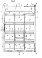
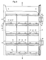
- a drawer magazine 1 which, for example, for the separate storage and / or storage of various small parts, such as bsow. Screws, nuts, washers or the like can be used.
- This drawer magazine has a housing 2, which contains several, for example four superimposed compartments 3, while each is in turn separated by dividers and / or guide webs 4 or by stiffening walls 5 into several, for example three, adjacent compartments 6 .
- the housing 2 has two completely closed side walls 7 and 8, a likewise completely closed ceiling 9 and a likewise completely closed bottom 10.
- the rear wall 11 of the housing 2 is not completely closed, but is respectively formed by short wall sections 11 'and 11 ", the wall section 11' connecting upwards to the ceiling 9, while each wall section 11" as an upward, strip-shaped Extension of the base 10 or of the shelves 12 formed between them and the ceiling 9 at a distance from one another.
- the ceiling 9 of the housing 1 is between the two side walls 7 and 8 as a trough-shaped recessed storage compartment 13, for example for tools or the like. executed and above it a handle bar 14 is inserted between the side walls 7 and 8, which enables easy transport of the drawer magazine 1.
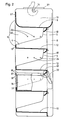
- the strip-shaped wall sections 11 ′′ at the rear end of the shelves 12 and the shelf 10 form insertion boundaries for the drawers -15 inserted into the individual compartments 6 of the compartments 3, as can be clearly seen in FIG. 2.
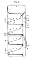
- the drawers 15 forming the drawer magazine 1 in connection with the housing 2 consist of known, standard storage boxes, in particular storage boxes, which have an at least three-sided circumferential stacking edge 16 which is angled sideways outwards and upwards relative to the box body is profiled.
- the upwardly angled flange 17 'of the rear stacking edge section 16' of the storage boxes used as drawers 15 cooperates with a stop web 18 which is directed downwards from the front, upper boundary edge of each compartment 3 or compartment 6 as soon as the drawer 15 comes out of the Housing 1 is pulled out, as can be seen from Fig. 3.
- the stop web 18 has the shape of a downward and backward-facing hook member, the overall depth of which corresponds approximately to three times the width of the angled stacking edges 16 'of the storage boxes used as drawers 15. This ensures that the drawers 15 pulled out of the housing 2 still retain a secure support on the shelf 12 or the floor 10 of the housing 3 which supports them, as can also be seen in FIG. 3.
- Ig from F. 1 also shows that the stop webs 18 designed as hook members are designed with a total length, 20, which is shorter than the width of the compartments 6 in the individual compartments 3, such that the ends of the stop webs 18 are directed away from each other Have a distance 21 from the adjacent side walls 7 and 8 and from the stiffening walls 5.
- the total length 20 of the stop webs 18 designed as hooked links is matched to the clear width between the upwardly angled 17 "of the side stack edge sections 16" of the storage boxes used as drawers 15, so that these also have lateral guidance through the stop webs 18 receive.
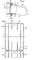
- separating and / or guide webs 4 While in many cases it is sufficient to provide separating and / or guide webs 4 on the individual shelves 12 or on the bottom 10 of the housing 1, which have a lower height than the strip-shaped wall sections 11 "of the rear wall 11, it is recommended if it is a matter of high stability of the housing 2, the separating and / or guide webs as stiffening walls 5 extending over the entire height of the compartments 3, each connected to the compartment ceiling and the compartment floor, as can be seen in FIG
- stiffening walls 5 do not need to be connected to the compartment ceiling over the entire compartment depth, but it is also sufficient if they are connected to the respective compartment ceiling only in the area in which the stop webs 18 are located is shown in Fig. 2.
- flaps or tabs 22 can also prove to be advantageous to link flaps or tabs 22 to the upper, front boundary edges of the individual compartments, which cover at least one upper section on the front transverse side of the storage boxes used as drawers 15.
- the length of the individual flaps or tabs 22 is preferably dimensioned such that it is visible Open the storage boxes used as drawers 15 completely.
- each flap or tab 22 into its covering position on the housing, in particular on the side walls 7 and 8 of the same .
- This is possible in a simple manner, for example, by inserting security rods through holes in both side walls 7 and 8, which can be fixed in position, for example, by small padlocks or other security elements.
- the upper wall section 11 'of the rear wall 11 of the housing 2 is equipped with keyhole-like, per filed, upwardly narrowed holes 23 into which are attached to the wall or on the support Retaining links with a thickened headboard can be indented.
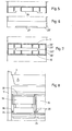
- each of the two side walls 7 and 8 of the housing 2 a plurality of holes 24 can also be provided, which offer engagement options for wire hooks 25, on which tools or other parts can in turn be suspended if necessary. If it is desired to arrange several drawer magazines 1 one above the other, as can be seen in FIG. 4, it is advisable to have a notch 26 on the lower transverse edge of each side wall 7 and 8 and a tongue on the upper transverse edge of each side wall 7 and 8 27 to be arranged (Fig. 1, 2 and 4 to 6), which then interlock when the housings 2, as shown in Fig. 4, are placed one on the other. A mutual, positive locking of the two housing 2 is then guaranteed.
- the side walls 7 and 8 of the housing 2 prefferably increase their dimensional stability with normal to their level teten stiffening webs 28 and to partially design them as peripheral webs 28 '.
- the notches 26 can then be located in the circumferential web 28 'assigned to the lower transverse edge of the side walls 7 and 8, as shown in FIG. 5, while the tongues 27 sit on the circumferential web 28' assigned to the upper transverse edge of the side walls 7 and 8, as can be seen from Fig. 6.
- the circumferential webs 28 'of one side wall 7 are provided with chamfers or folds 29' on the inside, while the other side wall is complementary for this purpose has chamfers or folds 29 "on the outside on the circumferential webs 28.
- the chamfers or folds 29 ', 29" come into mutual positive engagement, as can be seen from FIG. 7.
- the drawer magazine 1 according to FIGS. 9 to 11 has essentially the same configuration as that according to FIGS. 1 to 3. For this reason, the corresponding components or configurations are also provided with the same reference symbols.
- a larger number of locking cams 37 are arranged in each compartment 3 on the base 10 or the shelves 12.
- Fig. 9 in the left compartments 6 of all compartments 3 there is a latching cam 37, while in the middle and in the right compartment 6 of each compartment 3 there are two latching cams 37 on the bottom 10 and the shelves 12, respectively.
- the counter-catch 38 on the drawers 15, on the other hand, preferably consists of strips running across the entire width thereof, which ensures that it can interact with any possible arrangement of catch cams 37.
- the latching cams 37 have a steep flank 39 which faces the wall sections 11 ′′, in particular parallel to this flank 39 and also have a flank 40 which is flatly inclined and faces away from it.
- the counter-catch 38 on the drawers 15 is provided on the outside with a chamfer or rounding 41, while on the inside it has an engagement surface 42 which is normal to the bottom plane of the drawer 15.
- the two side walls 7 and 8 of the housing 2 can have openings 44 in their circumferential webs 28 ', specifically in the region of the housing front. These openings 44 are arranged and designed so that they can be used on the one hand as fastening interventions for hinges 45, but on the other hand are also useful for forming hook eyes for the shackles of padlocks 46.
- two structurally identical drawer magazines 1 can then be connected in an articulated manner such that their front sides of the housing can be pivoted either towards one another or away from one another.
- the drawer magazines 1 pivoted against one another can then be fixed against one another via the padlocks 46 and thus made inaccessible.
- Fig. 10 it is indicated that the hinges can be locked and / or braced in the openings 44 via molded projections 47.
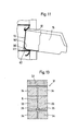
- molds 31, as shown in FIGS. 12 and 13, can then be used to produce the housings 2.
- These molds 31 are formed by a multi-part main mold 32 for the outer contours of the housing 2 and by associated core molds 33 and 34, the latter the inner contours of the housing 2 with the compartments 3, the separating and / or guide webs 4 or stiffening walls 5, determine the wall sections 11 "and the stop bars 18.
- the two core molds 33 and 34 are designed as trains which can be displaced to opposite sides relative to the multi-part main mold 32, in such a way that the core mold 34 forms the upper trains which can be moved backwards, while the core mold 33 forms the lower trains which can be moved forward having.
- the upper, rearwardly displaceable trains of the core mold 34 have at their front end the inner contour of the stop webs 18 designed as hook members, while their rear end has the outer contour for the wall sections 11 'and 11 " corresponds to the rear wall 11.
- the lower, forward-moving trains located on the core mold 33 have at their rear end the outer contour of the stop webs 18 designed as hooked links, while their front end is adapted to the inner contour of the strip-shaped rear wall sections 11 ".
- the trains of both core shapes 33 and 34 are, as shown in FIG. 13, also designed so that they form the inner contour for the separating and / or guide webs 4 or for the stiffening walls 5 of the compartments 3 with one another on their longitudinal sides.
- Fig. 8 a section of a drawer magazine is shown in a representation corresponding to Fig. 1, from which it follows that storage drawers can be used as drawers 15, which have sideways overhanging edge strips 34 on their bottom longitudinal edges.
- the interaction of the edge strips 34 and the support webs 35 significantly improves the guiding security of the latter when the drawers 15 are pulled out and pushed in.
- Fig. 13 shows that the cavities necessary for forming the support webs 35 can be created in the mold 31 by appropriate profiling of the trains on the core mold 33.
Landscapes
- Engineering & Computer Science (AREA)
- Mechanical Engineering (AREA)
- Manufacturing & Machinery (AREA)
- Drawers Of Furniture (AREA)
Applications Claiming Priority (2)
| Application Number | Priority Date | Filing Date | Title |
|---|---|---|---|
| DE8109516U | 1981-03-31 | ||
| DE19818109516U DE8109516U1 (de) | 1981-03-31 | 1981-03-31 | Schubladen-magazin, insbesondere fuer die vorratshaltung und/oder lagerung von kleinteilen |
Publications (3)
| Publication Number | Publication Date |
|---|---|
| EP0063250A2 true EP0063250A2 (fr) | 1982-10-27 |
| EP0063250A3 EP0063250A3 (en) | 1984-09-05 |
| EP0063250B1 EP0063250B1 (fr) | 1987-12-02 |
Family
ID=6726306
Family Applications (1)
| Application Number | Title | Priority Date | Filing Date |
|---|---|---|---|
| EP82102349A Expired EP0063250B1 (fr) | 1981-03-31 | 1982-03-22 | Rayonnage à tiroirs, pour le stockage de petites pièces |
Country Status (3)
| Country | Link |
|---|---|
| EP (1) | EP0063250B1 (fr) |
| DE (2) | DE8109516U1 (fr) |
| DK (1) | DK155773C (fr) |
Cited By (6)
| Publication number | Priority date | Publication date | Assignee | Title |
|---|---|---|---|---|
| EP0142284A3 (en) * | 1983-11-10 | 1986-08-27 | Sybron Corporation | A single-piece injection-moulded rack and a mould for its manufacture |
| GB2442935A (en) * | 2006-10-20 | 2008-04-23 | Certwood Ltd | Storage tray system |
| USD600948S1 (en) | 2007-01-29 | 2009-09-29 | Certwood Limited | Tray runner |
| CN110897454A (zh) * | 2019-12-13 | 2020-03-24 | 义乌拓延贸易有限公司 | 一种基于旋转运动进行全方位展览的文化用品智能展览装置 |
| CN113044341A (zh) * | 2021-03-24 | 2021-06-29 | 刘江涛 | 一种化工品运输保存装置 |
| CN113455833A (zh) * | 2021-07-02 | 2021-10-01 | 于彩霞 | 一种中医用便于取放药品的中药柜 |
Family Cites Families (4)
| Publication number | Priority date | Publication date | Assignee | Title |
|---|---|---|---|---|
| BE570805A (fr) * | ||||
| US2964371A (en) * | 1958-02-17 | 1960-12-13 | Imp Brass Mfg Co | Display merchandiser |
| DE1298950B (de) * | 1965-11-24 | 1969-07-03 | Hoewe August W | Traeger fuer Behaelter zur Aufnahme von Kleinteilen, wie Schrauben und sonstigen Montagenteilen |
| GB1328193A (en) * | 1972-03-13 | 1973-08-30 | Austin Leyton Ltd F | Drawer units |
-
1981
- 1981-03-31 DE DE19818109516U patent/DE8109516U1/de not_active Expired
-
1982
- 1982-03-22 EP EP82102349A patent/EP0063250B1/fr not_active Expired
- 1982-03-22 DE DE8282102349T patent/DE3277762D1/de not_active Expired
- 1982-03-24 DK DK132082A patent/DK155773C/da not_active IP Right Cessation
Cited By (10)
| Publication number | Priority date | Publication date | Assignee | Title |
|---|---|---|---|---|
| EP0142284A3 (en) * | 1983-11-10 | 1986-08-27 | Sybron Corporation | A single-piece injection-moulded rack and a mould for its manufacture |
| GB2442935A (en) * | 2006-10-20 | 2008-04-23 | Certwood Ltd | Storage tray system |
| GB2442935B (en) * | 2006-10-20 | 2009-10-28 | Certwood Ltd | Storage tray system |
| US7963408B2 (en) | 2006-10-20 | 2011-06-21 | Certwood Limited | Storage tray system |
| USD600948S1 (en) | 2007-01-29 | 2009-09-29 | Certwood Limited | Tray runner |
| CN110897454A (zh) * | 2019-12-13 | 2020-03-24 | 义乌拓延贸易有限公司 | 一种基于旋转运动进行全方位展览的文化用品智能展览装置 |
| CN113044341A (zh) * | 2021-03-24 | 2021-06-29 | 刘江涛 | 一种化工品运输保存装置 |
| CN113044341B (zh) * | 2021-03-24 | 2023-05-09 | 惠州大亚湾中润达物流服务有限公司 | 一种化工品运输保存装置 |
| CN113455833A (zh) * | 2021-07-02 | 2021-10-01 | 于彩霞 | 一种中医用便于取放药品的中药柜 |
| CN113455833B (zh) * | 2021-07-02 | 2022-11-08 | 聊城市蓓智信息科技有限公司 | 一种中医用便于取放药品的中药柜 |
Also Published As
| Publication number | Publication date |
|---|---|
| EP0063250A3 (en) | 1984-09-05 |
| DK155773C (da) | 1989-10-09 |
| DK155773B (da) | 1989-05-16 |
| DE3277762D1 (en) | 1988-01-14 |
| EP0063250B1 (fr) | 1987-12-02 |
| DE8109516U1 (de) | 1981-08-27 |
| DK132082A (da) | 1982-10-01 |
Similar Documents
| Publication | Publication Date | Title |
|---|---|---|
| DE69503390T2 (de) | Modulare aufbewahrungseinheit | |
| DE19627434A1 (de) | Bausatz einer zusammenlegbaren Papierablage | |
| DE8211051U1 (de) | Transportabler Vorrats- und/oder Lagerbehaelter fuer Kleinteile oder dergleichen | |
| DE2760376C2 (fr) | ||
| DE2915812A1 (de) | Stapelbarer transport- und lagersichtkasten aus kunststoff | |
| DE7926804U1 (de) | Verkaufsverpackung vorzugsweise vom Blasentyp | |
| EP0063805B1 (fr) | Rayonnage de stockage et de présentation d'objets | |
| EP3491970B1 (fr) | Boîte pour étagères | |
| EP0063250A2 (fr) | Rayonnage à tiroirs, pour le stockage de petites pièces | |
| DE2944683C2 (de) | Schubkasten, insbesondere für Büromöbel | |
| EP0043540A2 (fr) | Coffret à tiroirs cloisonnés pour assortiment | |
| DE3200142C2 (fr) | ||
| EP3006303A1 (fr) | Support mobile de presentation et de transport de marchandises | |
| DE3210441A1 (de) | Schubladen-magazin, insbesondere fuer die vorratshaltung und/oder lagerung von kleinteilen | |
| EP0275894B1 (fr) | Classeur pour documents sur chant | |
| DE7632783U1 (de) | Lagerkasten insbesondere zum Einstellen in Regale | |
| CH652012A5 (en) | Stackable filing container with pull-out drawer | |
| DE4012728C2 (fr) | ||
| DE202017107337U1 (de) | Regalbox mit Arretieranschlägen | |
| EP0173810A2 (fr) | Subdivision de rayon avec cloisons enfichables pour tiroirs ou similaires | |
| DE3310889A1 (de) | Regal aus einzelnen, stabelfaehigen lagerwannen oder lagerkaesten mit sichtoeffnung | |
| DE10308465A1 (de) | Auszug | |
| DE102022110515A1 (de) | Warenregal | |
| DE8210999U1 (de) | Regal aus einzelnen, stabelfaehigen lagerwannen oder lagerkaesten mit sichtoeffnung | |
| DE10308464A1 (de) | Auszug |
Legal Events
| Date | Code | Title | Description |
|---|---|---|---|
| PUAI | Public reference made under article 153(3) epc to a published international application that has entered the european phase |
Free format text: ORIGINAL CODE: 0009012 |
|
| 17P | Request for examination filed |
Effective date: 19820322 |
|
| AK | Designated contracting states |
Designated state(s): BE CH DE FR GB IT NL SE |
|
| PUAL | Search report despatched |
Free format text: ORIGINAL CODE: 0009013 |
|
| AK | Designated contracting states |
Designated state(s): BE CH DE FR GB IT LI NL SE |
|
| GRAA | (expected) grant |
Free format text: ORIGINAL CODE: 0009210 |
|
| AK | Designated contracting states |
Kind code of ref document: B1 Designated state(s): BE CH DE FR GB IT LI NL SE |
|
| REF | Corresponds to: |
Ref document number: 3277762 Country of ref document: DE Date of ref document: 19880114 |
|
| GBT | Gb: translation of ep patent filed (gb section 77(6)(a)/1977) | ||
| ET | Fr: translation filed | ||
| ITF | It: translation for a ep patent filed | ||
| PLBE | No opposition filed within time limit |
Free format text: ORIGINAL CODE: 0009261 |
|
| STAA | Information on the status of an ep patent application or granted ep patent |
Free format text: STATUS: NO OPPOSITION FILED WITHIN TIME LIMIT |
|
| 26N | No opposition filed | ||
| ITTA | It: last paid annual fee | ||
| PGFP | Annual fee paid to national office [announced via postgrant information from national office to epo] |
Ref country code: SE Payment date: 19940215 Year of fee payment: 13 |
|
| PGFP | Annual fee paid to national office [announced via postgrant information from national office to epo] |
Ref country code: FR Payment date: 19940223 Year of fee payment: 13 |
|
| PGFP | Annual fee paid to national office [announced via postgrant information from national office to epo] |
Ref country code: GB Payment date: 19940307 Year of fee payment: 13 |
|
| PGFP | Annual fee paid to national office [announced via postgrant information from national office to epo] |
Ref country code: NL Payment date: 19940331 Year of fee payment: 13 |
|
| PGFP | Annual fee paid to national office [announced via postgrant information from national office to epo] |
Ref country code: BE Payment date: 19940413 Year of fee payment: 13 |
|
| PGFP | Annual fee paid to national office [announced via postgrant information from national office to epo] |
Ref country code: CH Payment date: 19940624 Year of fee payment: 13 |
|
| EAL | Se: european patent in force in sweden |
Ref document number: 82102349.6 |
|
| PG25 | Lapsed in a contracting state [announced via postgrant information from national office to epo] |
Ref country code: GB Effective date: 19950322 |
|
| PG25 | Lapsed in a contracting state [announced via postgrant information from national office to epo] |
Ref country code: SE Effective date: 19950323 |
|
| PG25 | Lapsed in a contracting state [announced via postgrant information from national office to epo] |
Ref country code: LI Effective date: 19950331 Ref country code: CH Effective date: 19950331 Ref country code: BE Effective date: 19950331 |
|
| PGFP | Annual fee paid to national office [announced via postgrant information from national office to epo] |
Ref country code: DE Payment date: 19950524 Year of fee payment: 14 |
|
| BERE | Be: lapsed |
Owner name: FRITZ SCHAFER G.M.B.H. Effective date: 19950331 |
|
| PG25 | Lapsed in a contracting state [announced via postgrant information from national office to epo] |
Ref country code: NL Effective date: 19951001 |
|
| GBPC | Gb: european patent ceased through non-payment of renewal fee |
Effective date: 19950322 |
|
| PG25 | Lapsed in a contracting state [announced via postgrant information from national office to epo] |
Ref country code: FR Free format text: LAPSE BECAUSE OF NON-PAYMENT OF DUE FEES Effective date: 19951130 |
|
| REG | Reference to a national code |
Ref country code: CH Ref legal event code: PL |
|
| NLV4 | Nl: lapsed or anulled due to non-payment of the annual fee |
Effective date: 19951001 |
|
| EUG | Se: european patent has lapsed |
Ref document number: 82102349.6 |
|
| REG | Reference to a national code |
Ref country code: FR Ref legal event code: ST |
|
| PG25 | Lapsed in a contracting state [announced via postgrant information from national office to epo] |
Ref country code: DE Effective date: 19961203 |