EP0063379B1 - Vorrichtung zum Einlegen von Spulen - Google Patents
Vorrichtung zum Einlegen von Spulen Download PDFInfo
- Publication number
- EP0063379B1 EP0063379B1 EP82103292A EP82103292A EP0063379B1 EP 0063379 B1 EP0063379 B1 EP 0063379B1 EP 82103292 A EP82103292 A EP 82103292A EP 82103292 A EP82103292 A EP 82103292A EP 0063379 B1 EP0063379 B1 EP 0063379B1
- Authority
- EP
- European Patent Office
- Prior art keywords
- coil
- jig
- pusher
- push
- core
- Prior art date
- Legal status (The legal status is an assumption and is not a legal conclusion. Google has not performed a legal analysis and makes no representation as to the accuracy of the status listed.)
- Expired
Links
- 238000003780 insertion Methods 0.000 description 19
- 230000037431 insertion Effects 0.000 description 19
- 239000011810 insulating material Substances 0.000 description 9
- WABPQHHGFIMREM-UHFFFAOYSA-N lead(0) Chemical compound [Pb] WABPQHHGFIMREM-UHFFFAOYSA-N 0.000 description 7
- ORQBXQOJMQIAOY-UHFFFAOYSA-N nobelium Chemical compound [No] ORQBXQOJMQIAOY-UHFFFAOYSA-N 0.000 description 7
- 230000006835 compression Effects 0.000 description 2
- 238000007906 compression Methods 0.000 description 2
- 238000012986 modification Methods 0.000 description 2
- 230000004048 modification Effects 0.000 description 2
- 238000007493 shaping process Methods 0.000 description 2
- 230000001360 synchronised effect Effects 0.000 description 2
- 238000010276 construction Methods 0.000 description 1
- 238000001514 detection method Methods 0.000 description 1
- 238000000034 method Methods 0.000 description 1
- 230000002093 peripheral effect Effects 0.000 description 1
Images

Classifications
-
- H—ELECTRICITY
- H02—GENERATION; CONVERSION OR DISTRIBUTION OF ELECTRIC POWER
- H02K—DYNAMO-ELECTRIC MACHINES
- H02K15/00—Processes or apparatus specially adapted for manufacturing, assembling, maintaining or repairing of dynamo-electric machines
- H02K15/06—Embedding prefabricated windings in the machines
- H02K15/062—Windings in slots; Salient pole windings
- H02K15/065—Windings consisting of complete sections, e.g. coils or waves
- H02K15/067—Windings consisting of complete sections, e.g. coils or waves inserted in parallel to the axis of the slots or inter-polar channels
- H02K15/068—Strippers; Embedding windings by strippers
-
- Y—GENERAL TAGGING OF NEW TECHNOLOGICAL DEVELOPMENTS; GENERAL TAGGING OF CROSS-SECTIONAL TECHNOLOGIES SPANNING OVER SEVERAL SECTIONS OF THE IPC; TECHNICAL SUBJECTS COVERED BY FORMER USPC CROSS-REFERENCE ART COLLECTIONS [XRACs] AND DIGESTS
- Y02—TECHNOLOGIES OR APPLICATIONS FOR MITIGATION OR ADAPTATION AGAINST CLIMATE CHANGE
- Y02P—CLIMATE CHANGE MITIGATION TECHNOLOGIES IN THE PRODUCTION OR PROCESSING OF GOODS
- Y02P80/00—Climate change mitigation technologies for sector-wide applications
- Y02P80/30—Reducing waste in manufacturing processes; Calculations of released waste quantities
-
- Y—GENERAL TAGGING OF NEW TECHNOLOGICAL DEVELOPMENTS; GENERAL TAGGING OF CROSS-SECTIONAL TECHNOLOGIES SPANNING OVER SEVERAL SECTIONS OF THE IPC; TECHNICAL SUBJECTS COVERED BY FORMER USPC CROSS-REFERENCE ART COLLECTIONS [XRACs] AND DIGESTS
- Y10—TECHNICAL SUBJECTS COVERED BY FORMER USPC
- Y10T—TECHNICAL SUBJECTS COVERED BY FORMER US CLASSIFICATION
- Y10T29/00—Metal working
- Y10T29/49—Method of mechanical manufacture
- Y10T29/49002—Electrical device making
- Y10T29/49009—Dynamoelectric machine
-
- Y—GENERAL TAGGING OF NEW TECHNOLOGICAL DEVELOPMENTS; GENERAL TAGGING OF CROSS-SECTIONAL TECHNOLOGIES SPANNING OVER SEVERAL SECTIONS OF THE IPC; TECHNICAL SUBJECTS COVERED BY FORMER USPC CROSS-REFERENCE ART COLLECTIONS [XRACs] AND DIGESTS
- Y10—TECHNICAL SUBJECTS COVERED BY FORMER USPC
- Y10T—TECHNICAL SUBJECTS COVERED BY FORMER US CLASSIFICATION
- Y10T29/00—Metal working
- Y10T29/53—Means to assemble or disassemble
- Y10T29/5313—Means to assemble electrical device
- Y10T29/53143—Motor or generator
- Y10T29/53161—Motor or generator including deforming means
Definitions
- the invention relates to an apparatus for inserting a coil into a core comprising a coil inserting jig for accommodating and retaining a coil therein, a coil pusher for inserting the coil into the core, a coil lifting apparatus composed of a coil wrapping jig supporting the outer parts of the coil, which wrapping jig is adapted to be moved synchronously with the coil pusher.
- the apparatus for inserting a coil into a core is characterized by means for driving said coil wrapping jig in response to the force applied by said coil pusher to the coil, to hold down or lift up the outer parts of the coil.
- the coil wrapping jig is driven very smoothly in response to the force applied by the coil pusher which force is detected by a sensing element contained in the coil pusher.
- the driving means includes a piezo-electric element contained within the coil pusher for receiving a force proportional to the force applied to the coil.
- said driving means further includes a cylinder to be actuated by means of the piezo-electric element, for driving the coil wrapping jig.
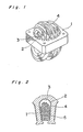
- a stator of an electric machine which is generally composed in a condition where within a stator core 1 having a plurality of grooves 3, a coil 4 and an insulating material piece 5 are inserted into the groove 3 insulated by an insulating paper 2 of the stator core 1.
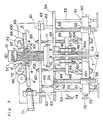
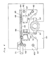
- Figs. 3 to 5 show a coil inserting apparatus for inserting automatically the coil 4 and insulating material piece 5 into the groove 3 of the stator core 1 on the application of a small insertion- required force, said apparatus comprising a coil inserting jig 6 for accommodating the coil 4 and retaining the coil, a coil pusher 101 for inserting into the core 1 the coil 4 accommodated in said coil inserting jig 6, a coil lifting apparatus composed of a coil wrapping jig 57, which is adapted to hold down the coil 4 provided around the coil inserting jig 6 or to lift up the coil to insert into the core 1, and means for driving said coil wrapping jig 57 supporting the coil 4 in response to a force applied upon said coil pusher 101 to hold down or lift up the coil during the coil insertion.
- the coil inserting jig 6 is always positioned in align with the coil 4 to be inserted into the grooves of the stator core 1, and a coil push rod 7 is applied to move vertically to engage with and push up the coil pusher 101, as shown in Fig. 5, provided within the coil inserting jig 6 in order to insert the coil 4 into the grooves of the stator core in a known manner, as disclosed within U.S. Patent No. 4,186,478 of the same applicant granted on February 5, 1980. Also, an insulating material piece push-moving-body 8 is used to insert an insulating material piece 5 (not shown in Fig. 3), accommodated within the coil inserting jig 6, into the groove 3 of the stator core 1.
- a housing 9 is secured on a flange 10 provided at the center of a base plate 54 fixed at a position to support slidably the coil push rod 7 and the insulating material piece push-moving-body 8 therethrough.
- a positioning apparatus 11 provided at a fixed position for guiding the coil inserting jig 6 matches, above the housing 9, with the lower portion of the coil inserting jig 6, while a cap plate 12 for pressing downwardly with a constant force by means of a pressure governor G (not shown in Fig. 3) comes into contact against the upper surface of the stator core 1 engaging with the coil inserting jig 6.
- a retaining plate 44 has a groove for setting the under portion of the insulating material piece push-moving-body 8 at equal intervals along the peripheral direction to secure the insulating material piece push-moving-body 8, and the coil push rod 7 is secured axially to the center of the retaining plate 44 which is secured on a push moving body 50, in a known manner.
- the coil push rod 7 is provided, at its tip end, with a flat portion for engagement and disengagement of the coil pusher 101.
- a guide moving body 46 has a plurality of holes for guiding the middle portion of the insulating material push-moving-body 8, and has a hole 46a at its center for passing through the coil push rod 7 and two holes at both sides in parallel to the hole 46a, the hole 46a being larger than the coil push rod 7 and the two holes having a slide bearing 47 internally engaged.
- a guide shaft 48 is slidable provided within the slide bearing 47, and is secured, at its tip end, to a support plate 49 which is secured on the base plate under the housing 9.
- the push moving body 50 provided with the retaining plate 44 secures a pair of slide bearings 51 respectively right and left in its axial direction, and also has a pair of ball screw bearings 52 having threads therein secured respectively right and left close to and in parallel to the slide bearings 51.
- a shaft 53 is secured, at its both ends, to the base plate 54 and an under fixed plate (not shown), and is adapted to guide the slide bearing 51 thereon, which is in internal contact between the push moving body 50 and the shaft 53.
- a ball screw shaft 55 having threads thereon is adapted to mesh with the ball screw bearings 52 to move it up and down together with the push moving body 50.
- the both ends of the ball screw shaft 55 are rotatably mounted through bearings 56, 56' and bearings (not shown), respectively on the base plate 54 and the under fixed plate (not shown).
- the output shaft of a motor M (not shown) provided under the push moving body 50 is coupled to the ball screw shaft 55 by a chain sprocket (not shown) so that the ball screw shaft 55 is driven in rotation by the motor to move the ball screw bearing 52 up and down.
- a hydraulic cylinder 71 is provided on a movable plate 61 disposed over the base plate 54 and has its rod coupled to a rack 65 to be guided with a support 64 provided on the movable plate 54.
- a gear 66 to be interlocked with the rack 65, is coupled to a coil wrapping jig 57 of type referred to a normal coil shaping jig for reduction of the coil insertion resistance by the shaft 72 which is supported on a bearing housing 67 provided on the movable plate 54.
- the bearing housing 67 supports rotatably the shaft 72 of the gear 66 and the coil wrapping jig 57.
- a coil lifting apparatus 100 is composed of a cylinder 71, a rack 65, a gear 66, a bearing housing 67, a support 64 and a coil wrapping jig 57.
- the rack 65 moves along the support 64 to rotate the rack 65 together with the coil wrapping jig 57 in the direction of clockwise and counterclockwise.
- a screw shaft 60 varies the interval between the movable plate 61 and the pushing plate 59 to couple them at a given distance.
- a shaft 62 is fixedly mounted on the base plate 54 and is slidably guided by the slide bearing 63, which is internally engaged with the movable plate 61.
- a stopper 68 is fixedly mounted on the base plate 54 to provide a stopper for the movable plate 61 to prevent it from moving downwards.
- a compression spring 69 is provided between the base plate 54 and the pushing plate 59 to push downwardly the pushing plate 59 to a cylinder 104 provided on the push moving body 50.
- a pair of microswitches 74 and 75 for actuating the cylinder 104 are provided at certain positions near the push moving body 50 and a dog 73 provided on the push moving body 50 is adapted to kick the microswitches 74 and 75 during the movement of the push moving body 50.
- the cyJinder 104 is actuated by its rod 107 to push upwards the pushing plate 59 against the compression spring 69.
- a piezo-electric element 102 is provided built-in within the coil pusher 101 for receiving a force proportional to a force the coil pusher 101 receives from the push moving body 50 to be moved upwardly by the actuation of the motor.
- a lead wire 103 is connected to the piezo-electric element 102 and the terminal thereof is connected to in series a relay 105 and a controller unit C (not shown) of the relay inserted halfway of the lead wire.
- a current for the lead wire 103 may flow only when a force applied upon the piezo-electric element 102 increases up to a certain amount.
- the lead wire of the relay 105 is further connected to a solenoid valve 106 which is adapted to control the operation of the hydraulic cylinder 104.
- the motor (not shown) is operated by means of the microswitch 75, and the ball screw shaft 55 is rotated to raise the push moving body 50 upward along the shaft 53.
- the coil push rod 7 secured to the push moving body 50 is raised upwardly together with the insulating material push-moving-body 8 to engage with the coil pusher 101 located within the coil jig 6, and the coil pusher 101 is coupled to the coil push rod 45 to raise together, as shown in Fig. 5.
- the dog 73 of the push moving body 50 actuates a microswitch 74 to operate the hydraulic cylinder 71, and the piston of the hydraulic cylinder 71 moves together with the rack 65 along the support 64 in a direction shown in an arrow X of Fig. 6 to rotate the gear 66 in a direction of arrow Y. Therefore, the coil wrapping jig 57 pivots with the rotation of the rack 65 from a position A to a position B through the shaft 72 in the arrow direction Y of Fig. 6, thereby to slightly raise the coil 4 upward. In this position, the cylinder rod 107 of the cylinder 104 is adjusted to be located immediately before coming into contact against the plate 59, and the movable plate 61 is located on the stopper 68 at the lowest position by means of the spring 69.
- the plate 59 is going to move and raise through the pushing of the cylinder rod 107, whereby the movable plate 61 is rendered to raise upward against the spring 69, which is coupled to the plate 59 through the shaft 60.
- the coil pusher 101 which is inserting the coil 4 into the core 1 at this time receives the downward insertion resistance by the coil 4, and the piezo-electric element 102 built-in within the coil pusher 101 receives a force proportional to a force applied upon the coil pusher 101. If a force applied upon the coil pusher 101 abruptly increases, a current of the piezo-electric element 102 flows to a lead wire 103 to operate a relay 105, thereby to open a solenoid valve 106 to control the operation of the hydraulic cylinder 104.
- the hydraulic cylinder 104 is actuated to further raise the plates 59 and 61 from the lower position to the upper position against the spring 69, and, thus, the coil 4 is further raised up by the coil wrapping jig 57 provided on the plate 61.
- a current flows from the piezo-electric element 102 provided within the coil pusher 101, when insertion resistance applied upon the coil pusher 101 has increased to drive the hydraulic cylinder 104 through the relay and solenoid valve thereby to raise the coil wrapping jig 57, while, when the insertion pressure has suddenly increased, the current reduces to stop the operation of the hydraulic cylinder 104 thereby to fundamentally keep the coil wrapping jig 57 synchronous to the motion of the coil pusher 101.
- the insertion pressure for the coil 4 into the core 1 can be effectively reduced, during the raising of the coil wrapping jig 57, through the synchronous relation of the coil wrapping jig with the receiving force of the coil pusher 101, so that the trouble for the insertion of the coil 4 into the core 1 may be prevented from being caused or the stator core may be prevented from being deformed.
- the coil wrapping jig 57 was used as a coil shaping jig for reduction of the coil insertion resistance.
- a coil controlling means from the flank as shown in Japanese Patent Laid Open Publication No. 78001/1978 can be used in place of the coil wrapping jig 57. Therefore, unless otherwise such changes and modifications depart from the scope of the present invention, they should be construed as included therein.
Landscapes
- Engineering & Computer Science (AREA)
- Manufacturing & Machinery (AREA)
- Power Engineering (AREA)
- Manufacture Of Motors, Generators (AREA)
Claims (3)
Applications Claiming Priority (2)
| Application Number | Priority Date | Filing Date | Title |
|---|---|---|---|
| JP56061078A JPS57177255A (en) | 1981-04-21 | 1981-04-21 | Coil inserting apparatus |
| JP61078/81 | 1981-04-21 |
Publications (2)
| Publication Number | Publication Date |
|---|---|
| EP0063379A1 EP0063379A1 (de) | 1982-10-27 |
| EP0063379B1 true EP0063379B1 (de) | 1985-08-07 |
Family
ID=13160728
Family Applications (1)
| Application Number | Title | Priority Date | Filing Date |
|---|---|---|---|
| EP82103292A Expired EP0063379B1 (de) | 1981-04-21 | 1982-04-20 | Vorrichtung zum Einlegen von Spulen |
Country Status (4)
| Country | Link |
|---|---|
| US (1) | US4457067A (de) |
| EP (1) | EP0063379B1 (de) |
| JP (1) | JPS57177255A (de) |
| DE (1) | DE3265189D1 (de) |
Family Cites Families (7)
| Publication number | Priority date | Publication date | Assignee | Title |
|---|---|---|---|---|
| GB1391972A (en) * | 1971-03-19 | 1975-04-23 | Gen Electric | Apparatus for forming and inserting insulators in a magnetic core |
| US3791419A (en) * | 1972-10-16 | 1974-02-12 | Essex International Inc | Apparatus and method for forming wave winding for dynamoelectric machine |
| DE2630183C3 (de) * | 1976-07-05 | 1986-07-31 | Otto 7980 Ravensburg Rist | Vorrichtung zum Einziehen von Wicklungen in Nuten von Statoren von Elektromotoren |
| JPS5389901A (en) * | 1977-01-18 | 1978-08-08 | Matsushita Electric Ind Co Ltd | Stator manufacturing method its device for electrical machinery |
| JPS5714539Y2 (de) * | 1977-07-08 | 1982-03-25 | ||
| JPS56112860A (en) * | 1980-02-06 | 1981-09-05 | Matsushita Electric Ind Co Ltd | Inserting device of coil |
| JPS5910143B2 (ja) * | 1980-02-06 | 1984-03-07 | 松下電器産業株式会社 | コイル插入装置 |
-
1981
- 1981-04-21 JP JP56061078A patent/JPS57177255A/ja active Granted
-
1982
- 1982-04-20 EP EP82103292A patent/EP0063379B1/de not_active Expired
- 1982-04-20 DE DE8282103292T patent/DE3265189D1/de not_active Expired
- 1982-04-21 US US06/370,550 patent/US4457067A/en not_active Expired - Fee Related
Also Published As
| Publication number | Publication date |
|---|---|
| DE3265189D1 (en) | 1985-09-12 |
| EP0063379A1 (de) | 1982-10-27 |
| US4457067A (en) | 1984-07-03 |
| JPH0514508B2 (de) | 1993-02-25 |
| JPS57177255A (en) | 1982-10-30 |
Similar Documents
| Publication | Publication Date | Title |
|---|---|---|
| US4366618A (en) | Apparatus for winding armatures of electric machines | |
| CN106956937A (zh) | 一种带自动供给功能的料盒机构 | |
| AU771885B2 (en) | Continuous winding process and apparatus for electrical transformer cores | |
| US4433475A (en) | Coil insertion apparatus | |
| US4538533A (en) | Workpiece holding-down device for a sewing machine | |
| US4457067A (en) | Coil inserting apparatus | |
| US5018269A (en) | Method for press-installing wires | |
| DE2407275A1 (de) | Regeleinrichtung fuer hydraulische aufzuege | |
| KR20110059270A (ko) | 차량 에이비에스용 노말 클로우즈 솔레노이드 밸브의 슬리브 조립장치 및 조립방법 | |
| US3176466A (en) | Hydraulic press | |
| CN221135786U (zh) | 半自动操作的电磁阀封装压床 | |
| JP2570088B2 (ja) | フローティングユニット | |
| JPH07284877A (ja) | 油圧制御鋲打機 | |
| KR940005717B1 (ko) | 반도체 조립장치용 공급장치 | |
| JP2522740Y2 (ja) | 板状物の小径穴打抜き装置 | |
| JPS5910143B2 (ja) | コイル插入装置 | |
| JPH0649867Y2 (ja) | 電子ガバナ装置 | |
| US4989309A (en) | Blade binding cord guiding arrangement for venetian blind making machine | |
| JP3816140B2 (ja) | シャーリングマシン | |
| CN216227435U (zh) | 磁组件自动装配设备的焊接装置 | |
| KR930004177Y1 (ko) | 안전장치를 가진 소형 프레스 | |
| JP3863220B2 (ja) | 電磁弁 | |
| JP2539636B2 (ja) | 電子ガバナ装置 | |
| JPS62263899A (ja) | 粉末成形プレス用ダイセツト | |
| SU1221159A1 (ru) | Захват |
Legal Events
| Date | Code | Title | Description |
|---|---|---|---|
| PUAI | Public reference made under article 153(3) epc to a published international application that has entered the european phase |
Free format text: ORIGINAL CODE: 0009012 |
|
| AK | Designated contracting states |
Designated state(s): DE FR GB |
|
| 17P | Request for examination filed |
Effective date: 19821202 |
|
| GRAA | (expected) grant |
Free format text: ORIGINAL CODE: 0009210 |
|
| AK | Designated contracting states |
Designated state(s): DE FR GB |
|
| REF | Corresponds to: |
Ref document number: 3265189 Country of ref document: DE Date of ref document: 19850912 |
|
| ET | Fr: translation filed | ||
| PLBE | No opposition filed within time limit |
Free format text: ORIGINAL CODE: 0009261 |
|
| STAA | Information on the status of an ep patent application or granted ep patent |
Free format text: STATUS: NO OPPOSITION FILED WITHIN TIME LIMIT |
|
| 26N | No opposition filed | ||
| ITF | It: translation for a ep patent filed | ||
| PGFP | Annual fee paid to national office [announced via postgrant information from national office to epo] |
Ref country code: FR Payment date: 19940411 Year of fee payment: 13 |
|
| PGFP | Annual fee paid to national office [announced via postgrant information from national office to epo] |
Ref country code: GB Payment date: 19940412 Year of fee payment: 13 |
|
| PGFP | Annual fee paid to national office [announced via postgrant information from national office to epo] |
Ref country code: DE Payment date: 19940426 Year of fee payment: 13 |
|
| PG25 | Lapsed in a contracting state [announced via postgrant information from national office to epo] |
Ref country code: GB Effective date: 19950420 |
|
| GBPC | Gb: european patent ceased through non-payment of renewal fee |
Effective date: 19950420 |
|
| PG25 | Lapsed in a contracting state [announced via postgrant information from national office to epo] |
Ref country code: FR Effective date: 19951229 |
|
| PG25 | Lapsed in a contracting state [announced via postgrant information from national office to epo] |
Ref country code: DE Effective date: 19960103 |
|
| REG | Reference to a national code |
Ref country code: FR Ref legal event code: ST |