EP0063516A1 - Verfahren zum Messen von Verstärkungsänderungen in einem Laserverstärker und Vorrichtung zur Durchführung des Verfahrens - Google Patents
Verfahren zum Messen von Verstärkungsänderungen in einem Laserverstärker und Vorrichtung zur Durchführung des Verfahrens Download PDFInfo
- Publication number
- EP0063516A1 EP0063516A1 EP82400613A EP82400613A EP0063516A1 EP 0063516 A1 EP0063516 A1 EP 0063516A1 EP 82400613 A EP82400613 A EP 82400613A EP 82400613 A EP82400613 A EP 82400613A EP 0063516 A1 EP0063516 A1 EP 0063516A1
- Authority
- EP
- European Patent Office
- Prior art keywords
- pumping
- gain
- variations
- energy
- amplifier
- Prior art date
- Legal status (The legal status is an assumption and is not a legal conclusion. Google has not performed a legal analysis and makes no representation as to the accuracy of the status listed.)
- Granted
Links
- 238000000034 method Methods 0.000 title claims abstract description 18
- 238000005086 pumping Methods 0.000 claims abstract description 51
- 230000005855 radiation Effects 0.000 claims description 12
- 108091008695 photoreceptors Proteins 0.000 claims description 9
- 230000000694 effects Effects 0.000 claims description 5
- 238000005259 measurement Methods 0.000 description 8
- 238000010586 diagram Methods 0.000 description 7
- 229920000297 Rayon Polymers 0.000 description 4
- 230000008030 elimination Effects 0.000 description 4
- 238000003379 elimination reaction Methods 0.000 description 4
- 230000005284 excitation Effects 0.000 description 4
- 230000003287 optical effect Effects 0.000 description 4
- 239000002964 rayon Substances 0.000 description 4
- 230000010354 integration Effects 0.000 description 2
- 229910052779 Neodymium Inorganic materials 0.000 description 1
- 230000003321 amplification Effects 0.000 description 1
- 230000015572 biosynthetic process Effects 0.000 description 1
- 230000007423 decrease Effects 0.000 description 1
- 239000011521 glass Substances 0.000 description 1
- QEFYFXOXNSNQGX-UHFFFAOYSA-N neodymium atom Chemical compound [Nd] QEFYFXOXNSNQGX-UHFFFAOYSA-N 0.000 description 1
- 238000003199 nucleic acid amplification method Methods 0.000 description 1
Images




Classifications
-
- H—ELECTRICITY
- H01—ELECTRIC ELEMENTS
- H01S—DEVICES USING THE PROCESS OF LIGHT AMPLIFICATION BY STIMULATED EMISSION OF RADIATION [LASER] TO AMPLIFY OR GENERATE LIGHT; DEVICES USING STIMULATED EMISSION OF ELECTROMAGNETIC RADIATION IN WAVE RANGES OTHER THAN OPTICAL
- H01S3/00—Lasers, i.e. devices using stimulated emission of electromagnetic radiation in the infrared, visible or ultraviolet wave range
- H01S3/0014—Monitoring arrangements not otherwise provided for
Definitions
- the subject of the present invention is a device for measuring the variations in the gain of a laser amplifier as a function of the pumping energy and a method using this device. It finds an application in optics, in particular in the production of chains of laser amplifiers.
- FIGS. 1 and 2 Essentially two methods of measuring the gain of a laser amplifier are known. The means enabling them to be used are illustrated diagrammatically in FIGS. 1 and 2.
- the amplifier laser whose gain is to be measured bears the reference 10. It is conventionally constituted by an amplifier bar 12 around which a flash tube 14 is wound, supplied with electrical energy by a circuit 16.
- the device further comprises an oscillator laser 20 able to emit a pulse-shaped light radiation 22 which passes through the amplifier bar 12 at a distance R from the axis of this bar, this radiation being at a wavelength which is the one at which the gain measurement should be performed.
- the pulse 22 is amplified by the bar 12 when the latter is made amplifier under the effect of the optical pumping created by the flash tube.
- the output pulse 24 which appears at the output of the amplifier then has a higher energy than that of the input pulse 22.
- the system also comprises two semi-transparent plates 31 and 32 placed respectively at the input and at the output of the amplifier bar 12 and two photosensitive detectors 33 and 34 (calorimeters, photoelectric cells, etc.) capable of measuring a luminous energy.
- the operation of such a device is as follows.
- the blades 31 and 32 take part of the input 22 and output 24 pulses and direct this part to the detectors 33 and 34 which measure the corresponding energies. Measuring the ratio of these energies immediately gives the gain of the rod 12, for the value of the pumping energy used and for the radius R considered.
- the second method is illustrated in FIG. 2 where the device shown also comprises an amplifier laser 10 whose gain is to be measured, and an oscillator laser 40 which, unlike the laser 20 of the previous device, operates continuously.
- This laser emits radiation at the amplification wavelength of the bar 12.
- the laser 40 can for example be of the YAG type.
- the device shown also comprises a separating plate 42, a photoelectric detector 44 and a divider 46 of the signal delivered by 44 by an amount proportional to the power delivered by the laser 40.
- This device represents the variation over time of the signal delivered by the detector 44.
- This signal represents the light power Ps (t) measured at the output of the amplifier 10 for the radius R n. In the absence of optical pumping, this power is equal to the value Pe of the input radiation emitted by the laser 40.
- the power Ps (t) increases to a maximum value Pm, which is reached at an instant tm, then decreases to tend again towards Pe.
- This method has the advantage over the previous one of allowing the determination of the instant when the gain is maximum, which makes it possible to synchronize the different amplifiers of a laser chain.
- the object of the present invention is precisely a device and a method which avoid these two drawbacks since it makes it possible to obtain the desired variations in gain as a function of the pumping energy in a single shot, that is to say in a single pumping operation.
- the device is of the type which has been described in connection with FIG. 2 and it is characterized in that it further comprises a means for delivering a signal E (t) representing the growth of the pumping energy used during pumping and a means for extracting from the two signals G (t) and E (t) by elimination of the time t, a signal G (E) which represents variations in gain as a function of pumping energy.
- the present invention also relates to a method for implementing the device which has just been defined.
- This method consists first of all (and as in the second method of the prior art described above), recording the variations G (t) of the gain as a function of time for a fixed pumping energy and, unlike the prior art, simultaneously recording the variations in the pumping energy E (t) used throughout the pumping pulse, then determining the variations G (E) in the gain as a function of the energy E by elimination of the time parameter between the two functions G (t) and E (t).
- the variations in gain in the range between zero and the total energy used are thus obtained directly and in a single shot. The latter must naturally be chosen large enough so that the interval in question covers the desired range.
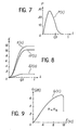
- the determination according to the invention of the variations in the gain as a function of the pumping energy requires the prior determination of the variations G (t) of the gain as a function of time and of those E (t) of the pumping energy as a function of this same time.
- the diagram in FIG. 4 represents the first, namely G (t), in a system of axes where time is shown on the abscissa (scale 0.1 ms per division) and the gain G on the ordinate (and expressed in dB) and that for a particular amplifier.
- This curve is obtained from the results illustrated in FIG. 3, taking as gain value the quotient of the output power Ps (t) of the amplifier by the input power Pe.
- This first determination can be made as in the prior art.
- the variations in voltage V (t) and in current I (t) applied to the flash tube are also measured simultaneously. These variations are illustrated respectively in FIGS. 5 and 6 where the time is still plotted on the abscissa with the same scale (0.1 ms per division), the voltage and the current being plotted on the ordinate, always for the particular amplifier in question. .
- the voltage scale is 1 kV per division and that of the currents is 5 kA per division.
- FIG. 7 represents the electrical power P (t) obtained by formation of the product V (t) .I (t).
- the power scale is, in the illustrated case, 30 MW per division.
- the time difference is always 0.1 ms per division.
- a signal G (E) is drawn by elimination of the time t, which is represented by the curve of the figure. 9 where the energy E is plotted on the abscissa (1 kJ per division) and the gain G on the ordinate (1 dB per division) for a radius R of the bar 12. According to the invention, this curve is obtained in a single shot.
- FIG. 10 The means making it possible to implement the process which has just been described are illustrated in FIG. 10. They comprise first of all and as in the prior art illustrated in FIG. 2, a source 40 of continuous radiation which operates at the measurement wavelength and which emits a power Pe. This radiation passes through the amplifier 12 whose gain is to be measured. A means 42 is used to take off part of the amplified radiation at the output of the amplifier, this means generally being a semi-transparent plate. A photoreceptor 44 receives the sampled part and measures the output power Ps during the entire duration of the optical pumping. Finally, a circuit 46 forms the quotient of Ps by Pe and delivers a signal G (t) which represents the variations in gain as a function of time during pumping.
- the device of FIG. 10 is characterized in that it further comprises a means 50 for measuring the growth E (t) of the pumping energy and a means 52 for drawing from the two signals G (t) and E (t ), by eliminating time t, the signal G (E) sought.
- the entire calculation chain described can be of an analog or digital character or of a hybrid digital-analog type.
- the measurement light beam has a low power.
- the gain measured is therefore a "small signal" gain.
- the diameter of this beam is generally much smaller than that of the laser amplifier, so that the gain measured is the gain at a well-determined distance from the axis (R) of the amplifier.
- R axis
- FIGS. 11a and 11b where we see a plurality of photoreceptors 70, 71, 72 ... re left along a radius at distances from the axis equal to R 0 , R 1 , R 2 , ... R n .
- These photodetectors can be photodiodes or elements of a Reticon array.
- FIG. 12 represents additional processing means making it possible to take full advantage of the device of FIG. 11 with several photodetectors.
- the time elimination means 52 receives, in addition to the signal E (t), as many signals G (t) as there are photoreceptors, ie G R1 (t), G R1 (t), G R2 (t), etc ... Instead of having only one output delivering a signal G (E), the means 52 has as many as there are photoreceptors.
- These outputs delivering signals representing the variations G R0 (E), G R1 (E), G R2 (E), etc. of the gain as a function of energy for the different radii R 0 , R 1 , R 2 ' etc ...
- These results are stored in means 100, 101, 102, etc ... (cf. the curves on the right of means 100, 101, 102, etc ).
- Means 110, 111, 112, etc., connected directly to means 100, 101, 102, etc., are capable of determining, for each radius R 0 , R 1 , R 2 ', etc., the value of the gain for a particular energy (E l ). These different values are taken into account by a means 120 which thus determines, for said value E 1 of the pumping energy, the variations in the gain G E1 (R) as a function of the radius R (cf. the curve represented on the right of the medium 120).
Landscapes
- Physics & Mathematics (AREA)
- Electromagnetism (AREA)
- Engineering & Computer Science (AREA)
- Plasma & Fusion (AREA)
- Optics & Photonics (AREA)
- Lasers (AREA)
- Photometry And Measurement Of Optical Pulse Characteristics (AREA)
Applications Claiming Priority (2)
| Application Number | Priority Date | Filing Date | Title |
|---|---|---|---|
| FR8106857A FR2503377A1 (fr) | 1981-04-06 | 1981-04-06 | Dispositif de mesure des variations du gain d'un amplificateur laser en fonction de l'energie de pompage et procede mis en oeuvre |
| FR8106857 | 1981-04-06 |
Publications (2)
| Publication Number | Publication Date |
|---|---|
| EP0063516A1 true EP0063516A1 (de) | 1982-10-27 |
| EP0063516B1 EP0063516B1 (de) | 1986-09-24 |
Family
ID=9257048
Family Applications (1)
| Application Number | Title | Priority Date | Filing Date |
|---|---|---|---|
| EP82400613A Expired EP0063516B1 (de) | 1981-04-06 | 1982-04-02 | Verfahren zum Messen von Verstärkungsänderungen in einem Laserverstärker und Vorrichtung zur Durchführung des Verfahrens |
Country Status (6)
| Country | Link |
|---|---|
| US (1) | US4507606A (de) |
| EP (1) | EP0063516B1 (de) |
| JP (1) | JPS57181188A (de) |
| CA (1) | CA1220358A (de) |
| DE (1) | DE3273404D1 (de) |
| FR (1) | FR2503377A1 (de) |
Families Citing this family (2)
| Publication number | Priority date | Publication date | Assignee | Title |
|---|---|---|---|---|
| US4573255A (en) * | 1984-03-22 | 1986-03-04 | At&T Bell Laboratories | Purging: a reliability assurance technique for semiconductor lasers utilizing a purging process |
| DE102023110595A1 (de) * | 2023-04-25 | 2024-10-31 | TRUMPF Lasersystems for Semiconductor Manufacturing SE | Vorrichtung und Verfahren zur Bestimmung der Leistung eines Laserstrahls |
Citations (3)
| Publication number | Priority date | Publication date | Assignee | Title |
|---|---|---|---|---|
| US3687558A (en) * | 1971-07-16 | 1972-08-29 | Us Air Force | Laser power-energy meter |
| FR2428829A1 (fr) * | 1978-06-16 | 1980-01-11 | Comp Generale Electricite | Dispositif de mesure de la fonction de coherence mutuelle d'un faisceau laser |
| DE3002558B1 (de) * | 1980-01-25 | 1981-04-02 | Vladimir Dr.-Ing. 5100 Aachen Blazek | Einrichtung zum Messen der Strahlungsleistung und der Strahlungsenergie von Lasern |
-
1981
- 1981-04-06 FR FR8106857A patent/FR2503377A1/fr active Granted
-
1982
- 1982-04-02 EP EP82400613A patent/EP0063516B1/de not_active Expired
- 1982-04-02 DE DE8282400613T patent/DE3273404D1/de not_active Expired
- 1982-04-05 US US06/365,158 patent/US4507606A/en not_active Expired - Fee Related
- 1982-04-05 CA CA000400460A patent/CA1220358A/fr not_active Expired
- 1982-04-05 JP JP57056491A patent/JPS57181188A/ja active Pending
Patent Citations (3)
| Publication number | Priority date | Publication date | Assignee | Title |
|---|---|---|---|---|
| US3687558A (en) * | 1971-07-16 | 1972-08-29 | Us Air Force | Laser power-energy meter |
| FR2428829A1 (fr) * | 1978-06-16 | 1980-01-11 | Comp Generale Electricite | Dispositif de mesure de la fonction de coherence mutuelle d'un faisceau laser |
| DE3002558B1 (de) * | 1980-01-25 | 1981-04-02 | Vladimir Dr.-Ing. 5100 Aachen Blazek | Einrichtung zum Messen der Strahlungsleistung und der Strahlungsenergie von Lasern |
Non-Patent Citations (3)
| Title |
|---|
| IEEE JOURNAL OF QUANTUM ELECTRONICS, vol. QE-15, no. 6, juin 1979, pages 510-523, New York, USA * |
| JAPANESE JOURNAL OF APPLIED PHYSICS, vol. 20, no. 1, janvier 1981, pages 71-74, Tokyo, JP. * |
| OPTICS COMMUNICATIONS, vol. 22, no. 3, septembre 1977, pages 288-292, Amsterdam, NL. * |
Also Published As
| Publication number | Publication date |
|---|---|
| CA1220358A (fr) | 1987-04-14 |
| EP0063516B1 (de) | 1986-09-24 |
| DE3273404D1 (en) | 1986-10-30 |
| FR2503377B1 (de) | 1983-10-14 |
| US4507606A (en) | 1985-03-26 |
| FR2503377A1 (fr) | 1982-10-08 |
| JPS57181188A (en) | 1982-11-08 |
Similar Documents
| Publication | Publication Date | Title |
|---|---|---|
| FR2574965A1 (fr) | Detecteur d'incendie du type a attenuation de la lumiere | |
| FR2644892A1 (fr) | Appareil de detection de gaz par absorption lumineuse | |
| EP0762145B1 (de) | Pulsverarbeitungssystem für einen Gammateilchen-CdTe-Strahlungsdetektor | |
| FR2756983A1 (fr) | Amplificateur optique et procede et dispositif de controle de gain d'amplificateur optique | |
| EP0234309A2 (de) | Verfahren und Vorrichtung zur Fernmessung der Verteilung eines physisch-chemischen Parameters in einem Medium | |
| FR2725791A1 (fr) | Procede et appareil de determination de facteur de bruit d'amplificateur optique | |
| EP1565763B1 (de) | Verbesserte schaltungsanordnung für spektrometrie und spektrometrisches system, das diese anordnung verwendet | |
| FR2738928A1 (fr) | Amplificateur optique | |
| EP0112762B1 (de) | Verfahren und Einrichtung zur laufenden Kontrolle der Schweisstiefe durch ein Impulsbündel | |
| EP0063516B1 (de) | Verfahren zum Messen von Verstärkungsänderungen in einem Laserverstärker und Vorrichtung zur Durchführung des Verfahrens | |
| CA2736593C (fr) | Systeme de controle de derive de gain de photomultiplicateur et procede associe | |
| EP2726853B1 (de) | Vorrichtung zur verwaltung von impulsen in einer pumpensondenspektroskopie | |
| CH630177A5 (fr) | Procede de commande de titrage et appareil pour la mise en oeuvre de ce procede. | |
| EP0782251A1 (de) | Detektor mit selbsttätiger Regelung der Vorspannung einer PIN-Fotodiode | |
| EP1927001B1 (de) | Laservorrichtung zum messen der luftgeschwindigkeit mit verbesserter augensicherheit | |
| FR2752068A1 (fr) | Systeme d'amplification optique ayant plusieurs unites de derivation et procede d'amplification optique | |
| FR2672754A1 (fr) | Systeme de localisation de reflexions de fresnel le long d'une fibre optique. | |
| FR2711792A1 (fr) | Dispositif de mesure de flux lumineux. | |
| FR3122742A1 (fr) | Procédé et dispositif d’analyse de modulation térahertz à cadence rapide, profonde et large bande | |
| EP0549464A1 (de) | Gerät und Verfahren zur Messung des Ladezustandes eines elektrochemischen Generators | |
| CH670718A5 (de) | ||
| FR2649419A1 (fr) | Procede de controle de l'epaisseur d'une couche antireflet et installation de mise en oeuvre | |
| FR2497356A1 (fr) | Camera a scintillation | |
| EP1786104B1 (de) | Anordnung zum Generieren von Synkronisiersignalen mit sehr niedrigem Jitter | |
| WO2023118462A1 (fr) | Procede et dispositif de type pyroreflectometre bichromatique pour determiner la temperature d'une surface |
Legal Events
| Date | Code | Title | Description |
|---|---|---|---|
| PUAI | Public reference made under article 153(3) epc to a published international application that has entered the european phase |
Free format text: ORIGINAL CODE: 0009012 |
|
| AK | Designated contracting states |
Designated state(s): DE GB IT |
|
| 17P | Request for examination filed |
Effective date: 19830331 |
|
| GRAA | (expected) grant |
Free format text: ORIGINAL CODE: 0009210 |
|
| AK | Designated contracting states |
Kind code of ref document: B1 Designated state(s): DE GB IT |
|
| REF | Corresponds to: |
Ref document number: 3273404 Country of ref document: DE Date of ref document: 19861030 |
|
| ITF | It: translation for a ep patent filed | ||
| PLBE | No opposition filed within time limit |
Free format text: ORIGINAL CODE: 0009261 |
|
| STAA | Information on the status of an ep patent application or granted ep patent |
Free format text: STATUS: NO OPPOSITION FILED WITHIN TIME LIMIT |
|
| 26N | No opposition filed | ||
| PG25 | Lapsed in a contracting state [announced via postgrant information from national office to epo] |
Ref country code: GB Free format text: LAPSE BECAUSE OF NON-PAYMENT OF DUE FEES Effective date: 19881121 |
|
| GBPC | Gb: european patent ceased through non-payment of renewal fee | ||
| PG25 | Lapsed in a contracting state [announced via postgrant information from national office to epo] |
Ref country code: DE Effective date: 19890103 |