EP0063536B1 - Conducteur électrique avec manchon protecteur contre la flexion - Google Patents
Conducteur électrique avec manchon protecteur contre la flexion Download PDFInfo
- Publication number
- EP0063536B1 EP0063536B1 EP82730041A EP82730041A EP0063536B1 EP 0063536 B1 EP0063536 B1 EP 0063536B1 EP 82730041 A EP82730041 A EP 82730041A EP 82730041 A EP82730041 A EP 82730041A EP 0063536 B1 EP0063536 B1 EP 0063536B1
- Authority
- EP
- European Patent Office
- Prior art keywords
- kink
- kink sleeve
- sleeve
- housing wall
- dome
- Prior art date
- Legal status (The legal status is an assumption and is not a legal conclusion. Google has not performed a legal analysis and makes no representation as to the accuracy of the status listed.)
- Expired
Links
- 238000005452 bending Methods 0.000 title description 2
- 239000004020 conductor Substances 0.000 title 1
- 238000003780 insertion Methods 0.000 claims abstract description 4
- 230000037431 insertion Effects 0.000 claims abstract description 4
- 239000013536 elastomeric material Substances 0.000 claims abstract description 3
- 239000004033 plastic Substances 0.000 claims abstract description 3
- 230000002093 peripheral effect Effects 0.000 claims abstract 4
- 235000001674 Agaricus brunnescens Nutrition 0.000 claims abstract 2
- 244000273618 Sphenoclea zeylanica Species 0.000 description 1
- 238000004026 adhesive bonding Methods 0.000 description 1
- 238000004873 anchoring Methods 0.000 description 1
- 239000011810 insulating material Substances 0.000 description 1
- 238000004519 manufacturing process Methods 0.000 description 1
- 239000007921 spray Substances 0.000 description 1
Images
Classifications
-
- H—ELECTRICITY
- H01—ELECTRIC ELEMENTS
- H01R—ELECTRICALLY-CONDUCTIVE CONNECTIONS; STRUCTURAL ASSOCIATIONS OF A PLURALITY OF MUTUALLY-INSULATED ELECTRICAL CONNECTING ELEMENTS; COUPLING DEVICES; CURRENT COLLECTORS
- H01R13/00—Details of coupling devices of the kinds covered by groups H01R12/70 or H01R24/00 - H01R33/00
- H01R13/56—Means for preventing chafing or fracture of flexible leads at outlet from coupling part
- H01R13/562—Bending-relieving
-
- H—ELECTRICITY
- H02—GENERATION; CONVERSION OR DISTRIBUTION OF ELECTRIC POWER
- H02G—INSTALLATION OF ELECTRIC CABLES OR LINES, OR OF COMBINED OPTICAL AND ELECTRIC CABLES OR LINES
- H02G3/00—Installations of electric cables or lines or protective tubing therefor in or on buildings, equivalent structures or vehicles
- H02G3/02—Details
- H02G3/08—Distribution boxes; Connection or junction boxes
- H02G3/081—Bases, casings or covers
- H02G3/083—Inlets
Definitions
- the invention is concerned with the structural design of an anti-kink sleeve which is arranged at the end of a flexible electrical line to be inserted into a portable electrical device.
- the cables are provided with an anti-kink sleeve anchored in the device.
- a known kink protection sleeve is made of plastic or elastomeric material and is firmly connected to the line.
- the anti-kink sleeve is provided with a circumferential recess in which an elastically resilient ring made of mechanically strong insulating material is attached is; this ring has a circumferential recess which serves to receive the wall of the housing (DE-A No. 2922655).
- This two-part design of the kink protection sleeve requires a corresponding manufacturing and assembly effort.
- connection line of a radio in the housing bushing
- spray a round rubber body on the connection line which is double-conical, has an annular groove in the middle, the width and depth of which is adapted to the corresponding opening in the housing wall, and the like a truncated cone is provided with axially extending slots. These slots are intended to allow an elastic reduction in diameter when the rubber body is inserted into the opening in the housing wall (US-A No. 2115495).
- the invention has for its object to improve the anchoring of the anti-kink sleeve in the housing wall by increasing the radial elastic deformability.
- the end of the kink protection sleeve lying on one side of the circumferential groove and to be inserted into the housing of the device is formed in a mushroom-shaped manner with a dome-like hat and with a stem and that the dome-like hat extends over the circumference supports evenly distributed bars on the stem.
- This design of the anti-kink sleeve gives greater radial elasticity of the front end of the anti-kink sleeve, so that when the electrical line provided with the anti-kink sleeve is inserted into the bore of a housing wall, the areas of the housing wall adjacent to the bore are deeper and thus more securely into the groove of the anti-kink sleeve can snap into place.
- the radial elasticity of one end of the kink protection sleeve can be improved in that the dome-like hat is provided with slits running parallel to the axis of the kink protection sleeve.
- the kink protection sleeve be designed in such a way that the rear end of the kink protection sleeve is tapered, similar to an e-function that is running out. It can be advantageous that the area of this end of the kink protection sleeve directly adjacent to the annular groove is initially cylindrical in order to ensure that the kink protection sleeve is supported in this area in a corresponding recess in the housing wall.
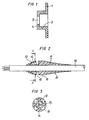
- FIGS. 1 to 3 An exemplary embodiment of a multi-core electrical line provided with the new kink protection sleeve, including the corresponding introduction into the housing of an electrical device, is shown in FIGS. 1 to 3.
- Fig. 1 shows in section the wall 1 of the housing of an electrical device in which a bore 2 is provided for the introduction of an electrical line and a corresponding kink protection sleeve.
- the bore 2 is located in a cylindrical insertion of the housing wall, which merges into the collar 4.
- the multi-core electrical line 10 is provided with the kink protection sleeve 11, which, for example, is manufactured separately and then pushed onto the line and integrally connected to it (for example by gluing), or which is sprayed onto the electrical line and thereby integrally with the jacket the line is connected.
- the kink protection sleeve is, seen overall, torpedo-like and young mushroom-shaped at the front end.
- the hollow stem 12 is penetrated by the line 10, while the dome-like hat 13 connects to this stem. This ends at the groove 15, which is delimited on the other side by the cylindrical piece 16 of the kink protection sleeve.
- This is followed by the rear end of the anti-kink sleeve, which is similar in region 17 or tapered in the manner of an expiring e-function.
- Fig. 3 shows a section of the anti-kink sleeve along the section line A-A.
- This sectional view shows that the dome-like hat is provided with slots 18 running in parallel to the axis of the kink protection sleeve and that the individual areas of the hat are supported on the stem 12 via webs 14.
Landscapes
- Engineering & Computer Science (AREA)
- Architecture (AREA)
- Civil Engineering (AREA)
- Structural Engineering (AREA)
- Insulating Bodies (AREA)
- Insulated Conductors (AREA)
- Insertion, Bundling And Securing Of Wires For Electric Apparatuses (AREA)
- Laying Of Electric Cables Or Lines Outside (AREA)
- Cable Accessories (AREA)
- Non-Insulated Conductors (AREA)
- Insulators (AREA)
Claims (2)
Priority Applications (1)
| Application Number | Priority Date | Filing Date | Title |
|---|---|---|---|
| AT82730041T ATE9748T1 (de) | 1981-04-06 | 1982-03-23 | Elektrische leitung mit knickschutztuelle. |
Applications Claiming Priority (2)
| Application Number | Priority Date | Filing Date | Title |
|---|---|---|---|
| DE19813114419 DE3114419A1 (de) | 1981-04-06 | 1981-04-06 | Elektrische leitung mit knickschutztuelle |
| DE3114419 | 1981-04-06 |
Publications (2)
| Publication Number | Publication Date |
|---|---|
| EP0063536A1 EP0063536A1 (fr) | 1982-10-27 |
| EP0063536B1 true EP0063536B1 (fr) | 1984-10-03 |
Family
ID=6129812
Family Applications (1)
| Application Number | Title | Priority Date | Filing Date |
|---|---|---|---|
| EP82730041A Expired EP0063536B1 (fr) | 1981-04-06 | 1982-03-23 | Conducteur électrique avec manchon protecteur contre la flexion |
Country Status (5)
| Country | Link |
|---|---|
| EP (1) | EP0063536B1 (fr) |
| AT (1) | ATE9748T1 (fr) |
| DE (2) | DE3114419A1 (fr) |
| ES (1) | ES272676Y (fr) |
| PT (1) | PT74698B (fr) |
Families Citing this family (7)
| Publication number | Priority date | Publication date | Assignee | Title |
|---|---|---|---|---|
| FR2547452B1 (fr) * | 1983-06-09 | 1990-02-02 | Renault | Garniture de traversee de paroi pour cable electrique |
| DE29922040U1 (de) | 1999-12-15 | 2000-03-30 | protec Kabel Produktion GmbH, 98574 Schmalkalden | Kupplung zum Halten von elektrischen Kabeln, Leitungen und Schläuche |
| DE102005005216A1 (de) | 2005-02-03 | 2006-08-10 | Neutrik Aktiengesellschaft | Knickschutzeinrichtung |
| DE102008002616A1 (de) * | 2008-06-24 | 2009-12-31 | Robert Bosch Gmbh | Kabeltülle für Handwerkzeugmaschine |
| DE102011056780A1 (de) * | 2011-12-21 | 2013-06-27 | Balluff Gmbh | Elektrisches Gerät und Verfahren zur Herstellung eines elektrischen Geräts |
| US9769551B2 (en) | 2014-12-31 | 2017-09-19 | Skullcandy, Inc. | Method of connecting cable to headphone, and headphone formed using such methods |
| DE102016109055A1 (de) | 2016-05-17 | 2017-11-23 | Deutsches Zentrum für Luft- und Raumfahrt e.V. | Freikolbenvorrichtung und Verfahren zum Betreiben einer Freikolbenvorrichtung |
Family Cites Families (4)
| Publication number | Priority date | Publication date | Assignee | Title |
|---|---|---|---|---|
| US2115495A (en) * | 1936-05-16 | 1938-04-26 | Gen Electric | Bushing |
| US2727088A (en) * | 1954-03-23 | 1955-12-13 | Gen Electric | Strain relief for electric cords |
| US3243835A (en) * | 1963-04-18 | 1966-04-05 | Gen Motors Corp | Bushing for electrical lead |
| FR2397084A1 (fr) * | 1977-07-06 | 1979-02-02 | Inst Francais Du Petrole | Embout de ligne flexible a raideur determinee variable |
-
1981
- 1981-04-06 DE DE19813114419 patent/DE3114419A1/de not_active Withdrawn
-
1982
- 1982-03-23 EP EP82730041A patent/EP0063536B1/fr not_active Expired
- 1982-03-23 AT AT82730041T patent/ATE9748T1/de not_active IP Right Cessation
- 1982-03-23 DE DE8282730041T patent/DE3260867D1/de not_active Expired
- 1982-04-02 PT PT74698A patent/PT74698B/pt unknown
- 1982-04-05 ES ES1982272676U patent/ES272676Y/es not_active Expired
Also Published As
| Publication number | Publication date |
|---|---|
| DE3260867D1 (en) | 1984-11-08 |
| ES272676U (es) | 1983-12-01 |
| PT74698B (de) | 1983-10-28 |
| ES272676Y (es) | 1984-06-16 |
| ATE9748T1 (de) | 1984-10-15 |
| EP0063536A1 (fr) | 1982-10-27 |
| DE3114419A1 (de) | 1982-10-21 |
| PT74698A (de) | 1982-05-01 |
Similar Documents
| Publication | Publication Date | Title |
|---|---|---|
| DE2101617A1 (de) | Kabelendabschirmung | |
| EP0396931B1 (fr) | Boîtier de terminaison pour connecteur électrique multipolaire à fiche | |
| EP0063536B1 (fr) | Conducteur électrique avec manchon protecteur contre la flexion | |
| DE69205257T2 (de) | Zusammengebauter Kommutator. | |
| DE3514010C1 (de) | Elektrische Steckverbindung | |
| DE1035723B (de) | Kupplungsvorrichtung fuer elektrische Kabel, insbesondere vieladrige Kabel | |
| DE4301504C2 (de) | Elektrischer Steckverbinder | |
| DE3005266A1 (de) | Elektrischer steckverbinder | |
| DE3220795A1 (de) | Getriebegehaeuse fuer elektrowerkzeuge | |
| DE3317348A1 (de) | Elektrische steckverbindungen | |
| EP0908995A1 (fr) | Press-étoupe pour câble blindé | |
| DE9411007U1 (de) | Zwei- oder mehrpoliger Stecker | |
| CH697606B1 (de) | Steckbare Kabelkupplung. | |
| DE2745887A1 (de) | Elektrisches verbindergehaeuse | |
| DE2817170C2 (de) | Innenrüttler | |
| DE7004948U (de) | Schutzkappe zum sichern von druckknopf-schaltern o.dgl. gegen staub, naesse o. dgl. | |
| DE8433788U1 (de) | Elektrischer Steckverbinder | |
| DE19964299B4 (de) | Steckverbinder für abstrahlende Koaxialkabel | |
| DE2626906A1 (de) | Kabelabgriff fuer niederspannungskabel | |
| DE9217862U1 (de) | Kabelendstecker für Koaxialkabel | |
| DE2425063A1 (de) | Elektrisches verbindungselement fuer koaxialkabel i | |
| AT1099U1 (de) | Verschlussstopfen | |
| DE8218120U1 (de) | Abdeckkappe für eine Steckvorrichtung | |
| DE2613612A1 (de) | Elektrische verbindung | |
| DE4027501C2 (de) | Abschlußwiderstand, insbesondere für Breitbandkommunikations-Kabellinien |
Legal Events
| Date | Code | Title | Description |
|---|---|---|---|
| PUAI | Public reference made under article 153(3) epc to a published international application that has entered the european phase |
Free format text: ORIGINAL CODE: 0009012 |
|
| AK | Designated contracting states |
Designated state(s): AT CH DE FR GB IT NL SE |
|
| 17P | Request for examination filed |
Effective date: 19830309 |
|
| ITF | It: translation for a ep patent filed | ||
| GRAA | (expected) grant |
Free format text: ORIGINAL CODE: 0009210 |
|
| AK | Designated contracting states |
Designated state(s): AT CH DE FR GB IT LI NL SE |
|
| REF | Corresponds to: |
Ref document number: 9748 Country of ref document: AT Date of ref document: 19841015 Kind code of ref document: T |
|
| REF | Corresponds to: |
Ref document number: 3260867 Country of ref document: DE Date of ref document: 19841108 |
|
| ET | Fr: translation filed | ||
| PLBE | No opposition filed within time limit |
Free format text: ORIGINAL CODE: 0009261 |
|
| STAA | Information on the status of an ep patent application or granted ep patent |
Free format text: STATUS: NO OPPOSITION FILED WITHIN TIME LIMIT |
|
| 26N | No opposition filed | ||
| PGFP | Annual fee paid to national office [announced via postgrant information from national office to epo] |
Ref country code: AT Payment date: 19860228 Year of fee payment: 5 |
|
| PGFP | Annual fee paid to national office [announced via postgrant information from national office to epo] |
Ref country code: NL Payment date: 19860331 Year of fee payment: 5 |
|
| PG25 | Lapsed in a contracting state [announced via postgrant information from national office to epo] |
Ref country code: AT Effective date: 19870323 |
|
| PG25 | Lapsed in a contracting state [announced via postgrant information from national office to epo] |
Ref country code: SE Effective date: 19870324 |
|
| PG25 | Lapsed in a contracting state [announced via postgrant information from national office to epo] |
Ref country code: LI Effective date: 19870331 Ref country code: CH Effective date: 19870331 |
|
| PG25 | Lapsed in a contracting state [announced via postgrant information from national office to epo] |
Ref country code: NL Effective date: 19871001 |
|
| NLV4 | Nl: lapsed or anulled due to non-payment of the annual fee | ||
| GBPC | Gb: european patent ceased through non-payment of renewal fee | ||
| PG25 | Lapsed in a contracting state [announced via postgrant information from national office to epo] |
Ref country code: FR Free format text: LAPSE BECAUSE OF NON-PAYMENT OF DUE FEES Effective date: 19871130 |
|
| REG | Reference to a national code |
Ref country code: CH Ref legal event code: PL |
|
| PG25 | Lapsed in a contracting state [announced via postgrant information from national office to epo] |
Ref country code: DE Effective date: 19871201 |
|
| REG | Reference to a national code |
Ref country code: FR Ref legal event code: ST |
|
| PG25 | Lapsed in a contracting state [announced via postgrant information from national office to epo] |
Ref country code: GB Effective date: 19881121 |
|
| EUG | Se: european patent has lapsed |
Ref document number: 82730041.9 Effective date: 19880215 |