EP0063675A1 - Dispositif pour la mise de planches ou de poutres de raidissement en dessous de paquets et pour le cerclage de celles-ci en croix - Google Patents
Dispositif pour la mise de planches ou de poutres de raidissement en dessous de paquets et pour le cerclage de celles-ci en croix Download PDFInfo
- Publication number
- EP0063675A1 EP0063675A1 EP82100993A EP82100993A EP0063675A1 EP 0063675 A1 EP0063675 A1 EP 0063675A1 EP 82100993 A EP82100993 A EP 82100993A EP 82100993 A EP82100993 A EP 82100993A EP 0063675 A1 EP0063675 A1 EP 0063675A1
- Authority
- EP
- European Patent Office
- Prior art keywords
- grooves
- parts
- tape
- stiffeners
- band guide
- Prior art date
- Legal status (The legal status is an assumption and is not a legal conclusion. Google has not performed a legal analysis and makes no representation as to the accuracy of the status listed.)
- Granted
Links
- 239000003351 stiffener Substances 0.000 claims description 16
- 230000037431 insertion Effects 0.000 claims 2
- 238000003780 insertion Methods 0.000 claims 2
- 230000002787 reinforcement Effects 0.000 abstract description 4
- 238000004806 packaging method and process Methods 0.000 description 21
- 238000012856 packing Methods 0.000 description 7
- 239000002023 wood Substances 0.000 description 6
- 230000006978 adaptation Effects 0.000 description 1
Images


Classifications
-
- B—PERFORMING OPERATIONS; TRANSPORTING
- B65—CONVEYING; PACKING; STORING; HANDLING THIN OR FILAMENTARY MATERIAL
- B65B—MACHINES, APPARATUS OR DEVICES FOR, OR METHODS OF, PACKAGING ARTICLES OR MATERIALS; UNPACKING
- B65B13/00—Bundling articles
- B65B13/02—Applying and securing binding material around articles or groups of articles, e.g. using strings, wires, strips, bands or tapes
- B65B13/04—Applying and securing binding material around articles or groups of articles, e.g. using strings, wires, strips, bands or tapes with means for guiding the binding material around the articles prior to severing from supply
- B65B13/06—Stationary ducts or channels
-
- B—PERFORMING OPERATIONS; TRANSPORTING
- B65—CONVEYING; PACKING; STORING; HANDLING THIN OR FILAMENTARY MATERIAL
- B65B—MACHINES, APPARATUS OR DEVICES FOR, OR METHODS OF, PACKAGING ARTICLES OR MATERIALS; UNPACKING
- B65B13/00—Bundling articles
- B65B13/18—Details of, or auxiliary devices used in, bundling machines or bundling tools
Definitions
- the invention relates to a device for criss-cross underlaying and strapping of board-like or beam-like stiffeners under packages on a table or a table-like frame with spaced-apart, open top grooves located below the support plane of the package, all of which are arranged in an upper plane and serve to introduce stiffeners, with further grooves arranged at a distance from each other in a lower plane at a distance from each other below these grooves of the upper level, for inserting stiffeners, with each groove of the lower level having a bottom in the middle in the middle Has band guide channel.
- stiffeners could only be underlaid in one direction if each stiffener should also be strapped.
- a layer had to be underlaid and strapped first. Then the package had to be lifted and placed on another table, or above the first table can be rotated by 90 °. It was only now that the stiffeners offset by 90 ° to the first layer of stiffeners could be underlaid and strapped.
- the present invention has for its object to provide a cross-wise under and strapping of stiffeners on a table without lifting and rotating the package in between, the stiffeners can be strapped in any plane.
- the packing table should be designed so that it can be adapted to the different sized packages and can also be strapped automatically.
- band guide channels sit below or in the lower region of the upper grooves and above the lower grooves the parts of the band guide channels belonging to the upper grooves are arranged to be folded away or pushed away at least in the entire width of the lower grooves.
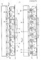
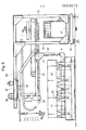
- the tables are made up of the three basic units 18, 19 and 20.
- the outer table parts 18 and 20 are arranged displaceably with respect to the firmly anchored middle part.
- the tables can easily be bypassed by people on all sides.
- B. Reinforcement corners by hand is necessary.
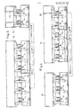
- 1, 3, 4 and 5 show the possibilities that result from the divisibility, based on the package size.
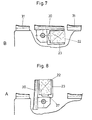
- the receptacles 23 are brought into position A, FIG. 8.
- the supports 26 are formed on the upper side such that boards, planks or beams 25 of different dimensions can be accommodated by the incorporated profile 24, FIG. 6, which represents a groove.
- the receptacles 23 provided with the pieces of wood 22 are pivoted into position B, FIG. 7, whereby a closed band guide by closing the bridges for the upper layer of wood 25 is created because the receptacles 23 contain parts 30 of the tape guide channel arranged one behind the other in grid spacing and covered by spring flaps.
- the tape guide channels 30 form with the part 31 of the tape guide channel fixedly arranged between the supports 26 the complete guidance of the packaging tape 28 belonging to the upper members 25 in the area below the package 13.
- the parts 31 of the band guides are also provided with spring flaps.
- the tape guides are tapered in a known manner.
- the wrapping of the packaging tapes 28 through the parts of the tape guide channel can be done manually, semi-automatically or fully automatically by strapping machines.
- the wood 25 is connected to the packages, which can have different sizes 13 to 16.
- the packaging straps can be tensioned and closed with compressed air equipment or automatic strapping machines.
- the receptacles 23 are pivoted into position A, FIG. 8, so that the opening of the receptacle is at the top. This opens the bridge for the tape guidance of the upper layer of wood 25, which is no longer required.
- the receptacles 23 are designed such that a lacing groove 27, FIG. 8, takes over the guiding of the packaging tape below the wood 22.
- the fulcrum for pivoting the receptacles 23 is selected so that the parts 30 and 31 of the band guide channel and the lacing grooves 27 are at a height in the position of use, so that strapping can be carried out longitudinally and transversely without this being adjusted in height must become.
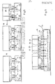
- a movable strapping station shown in FIGS. 9 and 10 is suitable for moving the packaging straps.
- the device for automatically moving packaging tape consists essentially of the motor-driven tape feed unit 32 and the channel system 33 used to guide the packaging tape.
- the complete strapping station is built on the base platform 34 and it can be moved so that on the one hand it is possible to run the cycle intervals between the lacing grooves 27 of the receptacles 23 of the packing tables and on the other hand the work area on several packing tables set up one behind the other, as shown in FIGS. 11 and 12 are shown to be able to expand.
- the packaging tapes 29 can be applied.
- the base plate 34 is equipped with a frame 35 which carried a cantilever arm 36.
- the carriage 37 is housed, on the underside of which a ball slewing ring 38 is attached.
- the actual tape transfer device consisting of tape feed unit 32 and channel system 33, 40 and 41, FIG. 9, is attached to the ball slewing ring 38.
- the turn-around system can be rotated through 90 ° to allow cross strapping to be put on.
- the frame 35 consists of two rear and a front support.
- the front support is provided on one side.
- the band bypass system is pivoted through 90 ° via the ball rotating connection 38, see FIG. 10.
- the parts 30 and 31 of the tape guide channel which are arranged several times one after the other in grid spacing, are scanned via the drive 39 of the carriage 37.
- An adaptation of the belt guide system to the variable pack table sizes and to the dimensional difference in length and width of the packages is required and is done by linear representation of the rear, vertical belt guide in the channel system 40.
- the duct bends in duct system 41 are fastened to the band guide of duct system 40 and are also adjusted.
- the lower channel arch located in the channel system 40 faces the lacing grooves 27 or the belt guides of the parts 30 and 31, depending on the position of the guide system, when the packaging tape is being guided around.
- the complete device for guiding the packaging tapes on the base plate 34 can be rotated through 180 ° by means of the ball rotating connection 42, FIG. 9, so that two arranged parallel to each other Rows of packing tables can be reached by the belt transfer device, see FIGS. 11 and 12.
Landscapes
- Engineering & Computer Science (AREA)
- Mechanical Engineering (AREA)
- Basic Packing Technique (AREA)
Applications Claiming Priority (2)
| Application Number | Priority Date | Filing Date | Title |
|---|---|---|---|
| DE3115827 | 1981-04-18 | ||
| DE3115827A DE3115827C2 (de) | 1981-04-18 | 1981-04-18 | Vorrichtung zum kreuzweisen Unterlegen und Umreifen von brett- oder balkenähnlichen Versteifungen unter Packstücken |
Publications (2)
| Publication Number | Publication Date |
|---|---|
| EP0063675A1 true EP0063675A1 (fr) | 1982-11-03 |
| EP0063675B1 EP0063675B1 (fr) | 1984-07-18 |
Family
ID=6130512
Family Applications (1)
| Application Number | Title | Priority Date | Filing Date |
|---|---|---|---|
| EP82100993A Expired EP0063675B1 (fr) | 1981-04-18 | 1982-02-11 | Dispositif pour la mise de planches ou de poutres de raidissement en dessous de paquets et pour le cerclage de celles-ci en croix |
Country Status (2)
| Country | Link |
|---|---|
| EP (1) | EP0063675B1 (fr) |
| DE (2) | DE3115827C2 (fr) |
Cited By (3)
| Publication number | Priority date | Publication date | Assignee | Title |
|---|---|---|---|---|
| DE3347865A1 (de) * | 1983-02-05 | 1985-05-02 | Berthold 7902 Blaubeuren Bührle | Vorrichtung zum umreifen eines quaderfoermigen gegenstandes |
| US4578933A (en) * | 1983-02-05 | 1986-04-01 | Georg Lang | Apparatus for strapping a cuboidal package |
| EP1400449A1 (fr) * | 2002-02-06 | 2004-03-24 | Gesellschaft für Forschung und Entwicklung wirtschaftlicher Produktionssysteme mbH -GFE- | Dispositif pour transporter des patins en dessous d'un paquet |
Families Citing this family (1)
| Publication number | Priority date | Publication date | Assignee | Title |
|---|---|---|---|---|
| DE3700146A1 (de) * | 1987-01-05 | 1988-07-14 | Forsch Entwicklung Wirtschaftl | Maschine zur umreifung von packstuecken in laengs- und querrichtung |
Citations (2)
| Publication number | Priority date | Publication date | Assignee | Title |
|---|---|---|---|---|
| US3494279A (en) * | 1968-06-24 | 1970-02-10 | Rowland L Sylvester | Support for use in strapping loads of multiple parts |
| FR2346222A1 (fr) * | 1976-04-03 | 1977-10-28 | Gerrard Ind Ltd | Appareil de cerclage d'une charge sur une palette |
-
1981
- 1981-04-18 DE DE3115827A patent/DE3115827C2/de not_active Expired
-
1982
- 1982-02-11 EP EP82100993A patent/EP0063675B1/fr not_active Expired
- 1982-02-11 DE DE8282100993T patent/DE3260387D1/de not_active Expired
Patent Citations (2)
| Publication number | Priority date | Publication date | Assignee | Title |
|---|---|---|---|---|
| US3494279A (en) * | 1968-06-24 | 1970-02-10 | Rowland L Sylvester | Support for use in strapping loads of multiple parts |
| FR2346222A1 (fr) * | 1976-04-03 | 1977-10-28 | Gerrard Ind Ltd | Appareil de cerclage d'une charge sur une palette |
Cited By (3)
| Publication number | Priority date | Publication date | Assignee | Title |
|---|---|---|---|---|
| DE3347865A1 (de) * | 1983-02-05 | 1985-05-02 | Berthold 7902 Blaubeuren Bührle | Vorrichtung zum umreifen eines quaderfoermigen gegenstandes |
| US4578933A (en) * | 1983-02-05 | 1986-04-01 | Georg Lang | Apparatus for strapping a cuboidal package |
| EP1400449A1 (fr) * | 2002-02-06 | 2004-03-24 | Gesellschaft für Forschung und Entwicklung wirtschaftlicher Produktionssysteme mbH -GFE- | Dispositif pour transporter des patins en dessous d'un paquet |
Also Published As
| Publication number | Publication date |
|---|---|
| DE3115827C2 (de) | 1983-05-11 |
| EP0063675B1 (fr) | 1984-07-18 |
| DE3115827A1 (de) | 1982-10-28 |
| DE3260387D1 (en) | 1984-08-23 |
Similar Documents
| Publication | Publication Date | Title |
|---|---|---|
| DE164062T1 (de) | Vorrichtung zum wechseln einer form in einer presse, insbesondere in einer spritzgiessmaschine. | |
| DE3111256A1 (de) | "einrichtung zum buntaufteilen von plattenfoermigen werkstuecken" | |
| DE3129709A1 (de) | Maschine zum schliessen der oberen deckelklappen eines quaderfoermigen kartons mit faltklappen | |
| DE69403555T2 (de) | Vorrichtung zum Anbringen von Kantenschützern an Palettenladungen | |
| DE3616922A1 (de) | Portalsaege zum quer- und laengsschneiden von platten-material | |
| DE3003628A1 (de) | Vorrichtung zum wechselseitigen einschieben von teilen in regalfaecher | |
| DE2330476C3 (de) | Plattenfertigaufteileinrichtung | |
| EP0063675B1 (fr) | Dispositif pour la mise de planches ou de poutres de raidissement en dessous de paquets et pour le cerclage de celles-ci en croix | |
| DE3301013A1 (de) | Sammelpackmaschine | |
| DE1953772A1 (de) | Vorrichtung zum Heben plattenfoermiger Traeger | |
| DE1228557B (de) | Foerdereinrichtung fuer die Benutzung bei einer Umschnuerungs- oder Umreifungsmaschine | |
| DE2638562A1 (de) | Vorrichtung zur herstellung von behaelterpacks, insbesondere von behaelterpacks fuer pastoese lebensmittel | |
| DE2545444B2 (de) | Vorrichtung zum Zusammenbauen von Möbelkorpussen | |
| DE1854784U (de) | Uebersetzungsvorrichtung fuer eine anlage zur herstellung von metallkonstruktionen. | |
| DE4333528C2 (de) | Vorrichtung zum Austrennen von vorzugsweise durch Tiefziehen geformten Behältern aus einem Folienstrang | |
| DE7100994U (de) | Format und Aufteilsage | |
| DE4240112A1 (de) | Kastenstapelvorrichtung | |
| DE3636269A1 (de) | Verfahren und maschine zur herstellung von schachtelzuschnitten aus unterschiedlichen materialien | |
| DE3909998C2 (de) | Plattenaufteilanlage mit wenigstens einer Längs- bzw. Quersäge zum Aufteilen von Plattenpaketen | |
| EP0240687A1 (fr) | Machine d'emballage | |
| DE29502308U1 (de) | Vorrichtung zum Transportieren von aus einem Blattpaketstapel entnehmbaren Blattpaketen | |
| DE3446852C2 (fr) | ||
| DE4109209A1 (de) | Vorrichtung und verfahren zum lagenstapeln von besaeumten und unbesaeumten schnittholz | |
| DE2330475A1 (de) | Plattenaufteileinrichtung | |
| DE3403998C2 (de) | Vorrichtung für die Bruttoabfüllung von Schüttgut in Säcke |
Legal Events
| Date | Code | Title | Description |
|---|---|---|---|
| PUAI | Public reference made under article 153(3) epc to a published international application that has entered the european phase |
Free format text: ORIGINAL CODE: 0009012 |
|
| AK | Designated contracting states |
Designated state(s): BE DE FR GB IT NL |
|
| ITCL | It: translation for ep claims filed |
Representative=s name: RICCARDI SERGIO & CO. |
|
| EL | Fr: translation of claims filed | ||
| TCNL | Nl: translation of patent claims filed | ||
| 17P | Request for examination filed |
Effective date: 19830121 |
|
| ITF | It: translation for a ep patent filed | ||
| GRAA | (expected) grant |
Free format text: ORIGINAL CODE: 0009210 |
|
| AK | Designated contracting states |
Designated state(s): BE DE FR GB IT NL |
|
| REF | Corresponds to: |
Ref document number: 3260387 Country of ref document: DE Date of ref document: 19840823 |
|
| ET | Fr: translation filed | ||
| RAP2 | Party data changed (patent owner data changed or rights of a patent transferred) |
Owner name: HOESCH AKTIENGESELLSCHAFT |
|
| BECN | Be: change of holder's name |
Effective date: 19840718 |
|
| PGFP | Annual fee paid to national office [announced via postgrant information from national office to epo] |
Ref country code: NL Payment date: 19850114 Year of fee payment: 4 |
|
| PGFP | Annual fee paid to national office [announced via postgrant information from national office to epo] |
Ref country code: DE Payment date: 19850121 Year of fee payment: 4 |
|
| PLBE | No opposition filed within time limit |
Free format text: ORIGINAL CODE: 0009261 |
|
| STAA | Information on the status of an ep patent application or granted ep patent |
Free format text: STATUS: NO OPPOSITION FILED WITHIN TIME LIMIT |
|
| 26N | No opposition filed | ||
| PG25 | Lapsed in a contracting state [announced via postgrant information from national office to epo] |
Ref country code: BE Effective date: 19860228 |
|
| NLT2 | Nl: modifications (of names), taken from the european patent patent bulletin |
Owner name: HOESCH AKTIENGESELLSCHAFT TE DORTMUND, BONDSREPUBL |
|
| BERE | Be: lapsed |
Owner name: HOESCH A.G. Effective date: 19860228 |
|
| PG25 | Lapsed in a contracting state [announced via postgrant information from national office to epo] |
Ref country code: NL Effective date: 19860901 |
|
| GBPC | Gb: european patent ceased through non-payment of renewal fee | ||
| NLV4 | Nl: lapsed or anulled due to non-payment of the annual fee | ||
| PG25 | Lapsed in a contracting state [announced via postgrant information from national office to epo] |
Ref country code: FR Free format text: LAPSE BECAUSE OF NON-PAYMENT OF DUE FEES Effective date: 19861031 |
|
| REG | Reference to a national code |
Ref country code: FR Ref legal event code: ST |
|
| PG25 | Lapsed in a contracting state [announced via postgrant information from national office to epo] |
Ref country code: DE Effective date: 19881101 |
|
| PG25 | Lapsed in a contracting state [announced via postgrant information from national office to epo] |
Ref country code: GB Effective date: 19881121 |