EP0063745A2 - Dispositif de régulation pour un onduleur autopiloté avec circuit intermédiaire en courant continu - Google Patents
Dispositif de régulation pour un onduleur autopiloté avec circuit intermédiaire en courant continu Download PDFInfo
- Publication number
- EP0063745A2 EP0063745A2 EP82103133A EP82103133A EP0063745A2 EP 0063745 A2 EP0063745 A2 EP 0063745A2 EP 82103133 A EP82103133 A EP 82103133A EP 82103133 A EP82103133 A EP 82103133A EP 0063745 A2 EP0063745 A2 EP 0063745A2
- Authority
- EP
- European Patent Office
- Prior art keywords
- voltage
- inverter
- input
- control
- value
- Prior art date
- Legal status (The legal status is an assumption and is not a legal conclusion. Google has not performed a legal analysis and makes no representation as to the accuracy of the status listed.)
- Granted
Links
Images

Classifications
-
- H—ELECTRICITY
- H02—GENERATION; CONVERSION OR DISTRIBUTION OF ELECTRIC POWER
- H02M—APPARATUS FOR CONVERSION BETWEEN AC AND AC, BETWEEN AC AND DC, OR BETWEEN DC AND DC, AND FOR USE WITH MAINS OR SIMILAR POWER SUPPLY SYSTEMS; CONVERSION OF DC OR AC INPUT POWER INTO SURGE OUTPUT POWER; CONTROL OR REGULATION THEREOF
- H02M5/00—Conversion of AC power input into AC power output, e.g. for change of voltage, for change of frequency, for change of number of phases
- H02M5/40—Conversion of AC power input into AC power output, e.g. for change of voltage, for change of frequency, for change of number of phases with intermediate conversion into DC
- H02M5/42—Conversion of AC power input into AC power output, e.g. for change of voltage, for change of frequency, for change of number of phases with intermediate conversion into DC by static converters
- H02M5/44—Conversion of AC power input into AC power output, e.g. for change of voltage, for change of frequency, for change of number of phases with intermediate conversion into DC by static converters using discharge tubes or semiconductor devices to convert the intermediate DC into AC
- H02M5/443—Conversion of AC power input into AC power output, e.g. for change of voltage, for change of frequency, for change of number of phases with intermediate conversion into DC by static converters using discharge tubes or semiconductor devices to convert the intermediate DC into AC using devices of a thyratron or thyristor type requiring extinguishing means
- H02M5/45—Conversion of AC power input into AC power output, e.g. for change of voltage, for change of frequency, for change of number of phases with intermediate conversion into DC by static converters using discharge tubes or semiconductor devices to convert the intermediate DC into AC using devices of a thyratron or thyristor type requiring extinguishing means using semiconductor devices only
- H02M5/4505—Conversion of AC power input into AC power output, e.g. for change of voltage, for change of frequency, for change of number of phases with intermediate conversion into DC by static converters using discharge tubes or semiconductor devices to convert the intermediate DC into AC using devices of a thyratron or thyristor type requiring extinguishing means using semiconductor devices only having a rectifier with controlled elements
-
- H—ELECTRICITY
- H02—GENERATION; CONVERSION OR DISTRIBUTION OF ELECTRIC POWER
- H02M—APPARATUS FOR CONVERSION BETWEEN AC AND AC, BETWEEN AC AND DC, OR BETWEEN DC AND DC, AND FOR USE WITH MAINS OR SIMILAR POWER SUPPLY SYSTEMS; CONVERSION OF DC OR AC INPUT POWER INTO SURGE OUTPUT POWER; CONTROL OR REGULATION THEREOF
- H02M7/00—Conversion of AC power input into DC power output; Conversion of DC power input into AC power output
- H02M7/42—Conversion of DC power input into AC power output without possibility of reversal
- H02M7/44—Conversion of DC power input into AC power output without possibility of reversal by static converters
- H02M7/48—Conversion of DC power input into AC power output without possibility of reversal by static converters using discharge tubes with control electrode or semiconductor devices with control electrode
- H02M7/505—Conversion of DC power input into AC power output without possibility of reversal by static converters using discharge tubes with control electrode or semiconductor devices with control electrode using devices of a thyratron or thyristor type requiring extinguishing means
- H02M7/515—Conversion of DC power input into AC power output without possibility of reversal by static converters using discharge tubes with control electrode or semiconductor devices with control electrode using devices of a thyratron or thyristor type requiring extinguishing means using semiconductor devices only
- H02M7/525—Conversion of DC power input into AC power output without possibility of reversal by static converters using discharge tubes with control electrode or semiconductor devices with control electrode using devices of a thyratron or thyristor type requiring extinguishing means using semiconductor devices only with automatic control of output waveform or frequency
- H02M7/527—Conversion of DC power input into AC power output without possibility of reversal by static converters using discharge tubes with control electrode or semiconductor devices with control electrode using devices of a thyratron or thyristor type requiring extinguishing means using semiconductor devices only with automatic control of output waveform or frequency by pulse width modulation
-
- F—MECHANICAL ENGINEERING; LIGHTING; HEATING; WEAPONS; BLASTING
- F02—COMBUSTION ENGINES; HOT-GAS OR COMBUSTION-PRODUCT ENGINE PLANTS
- F02B—INTERNAL-COMBUSTION PISTON ENGINES; COMBUSTION ENGINES IN GENERAL
- F02B3/00—Engines characterised by air compression and subsequent fuel addition
- F02B3/06—Engines characterised by air compression and subsequent fuel addition with compression ignition
Definitions
- the invention relates to a control arrangement for a self-commutated inverter operated according to the pulse-width modulation method with a DC voltage intermediate circuit, the control commands for the converter valves of the inverter being obtained by forming a control voltage with an auxiliary voltage.
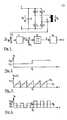
- a pulse width modulation method (undershoot method) is known, for example, from the BBC silicon power converter manual, 1971, pages 213 to 216. It is suitable for pulse width modulation for a self-commutated inverter with a DC link, as shown in FIGS. 1 to 4.
- 1 is a Two-phase DC link inverter with DC voltage DC link shown.
- the DC input voltage U E is present between the input terminals 1 and 2 of the intermediate circuit.
- a support capacitor 3 is connected to terminals 1 and 2.
- Ignitable and erasable converter valves 4 and 5 are connected to terminal 1 and converter valves 6 and 7 which are ignitable and erasable to terminal 2.
- the valves 4 and 6 and 5 and 7 are each connected to one another.
- At the common connection point of the valves 4 and 6 is the first terminal of an inductive consumer 8, the second terminal of which is connected to the common connection point of the valves 5 and 7.
- the output voltage U A is present between the terminals of the consumer 8.
- a current measuring device 9 is arranged in one of the power supply lines to the consumer 8 and outputs the actual current value U to an addition point 10 with a negative sign.
- the addition point 10 is present with a positive sign of the current setpoint U s .
- the addition point 10 is connected on the output side to a current regulator 11.
- the output-side control voltage U Y of the current regulator 11 is fed to an addition point 12 with a positive sign.
- the addition point 12 also has an auxiliary voltage U H with a negative sign.
- the addition point 12 is connected on the output side to a comparator 13.
- the comparator 13 issues switching commands S on the output side to a headset 14.
- the tax rate 14 delivers control pulses Z to the valves 4, 5, 6, 7.
- FIG. 2 shows the time profile of the input voltage U E.
- the input voltage U E rises from a constant value U El to a higher value U E2 .
- Fig. 3 the timing of the sawtooth H i LFSS p Annun g UH constant amplitude U H1, and the control voltage U Y are illustrated.
- the output voltage U A is pulsed, as shown in FIG. 4.
- the output voltage U in each case reaches the amplitude value U A1 and the mean value of the output voltage U A is U A1 .
- the amplitude of the output voltage reaches the increased value U A2 and the mean value of the output voltage U A increases to the value U A2 on.
- the invention is based on the object of specifying a control arrangement for a self-commutated inverter operated according to the pulse width modulation method with a DC voltage intermediate circuit, in which a disturbing change in the DC input voltage has no effect on the predetermined output voltage.
- This object is achieved in that a multiplier is provided, to which the DC input voltage of the intermediate circuit and a constant auxiliary voltage are fed as factors on the input side and which outputs an auxiliary voltage on the output side, the amplitude of which is proportional to the value of the DC input voltage.
- FIG. 5 shows a self-commutated inverter with a DC link and control arrangement.
- a supporting capacitor 3 and a voltage measuring device 15 are connected between the input terminals 1 and 2 of the intermediate circuit.
- Ignition and erasable converter valves 4 and 5 are connected to the terminal 1 and converter valves 6 and 7 which are ignitable and erasable to the terminal 2.
- a consumer 8 e.g. motor
- the output voltage of the inverter U is present at the consumer 8.
- 5 shows a two-phase inverter for simplification, but the invention is preferably used in three-phase inverters for supplying three-phase asynchronous motors.
- the DC input voltage U E present between the terminals 1 and 2 of the intermediate circuit is detected by the voltage measuring device 15, evaluated with a factor K and the value K.
- U E is fed to a multiplier 16.
- the sawtooth-shaped auxiliary voltage U B is fed to the multiplier 16 as a further factor.
- the auxiliary voltage on the output side of the multiplier U H U B. K.
- U E becomes an addition point 12 fed with a negative sign.
- the control point U Y is applied to the addition point 12 with a positive sign.
- the control voltage Uy can be specified in a controlled arrangement, or it is obtained in a regulated arrangement by means of a current or voltage or power regulator.
- control voltage U Y is determined with the aid of a current regulator 11 which is connected on the input side to an addition point 10.
- the addition point 10 On the input side, the addition point 10 has a current setpoint U s with a positive sign and an actual current value U I with a negative sign.
- the actual current value U 1 is determined with the aid of a current measuring device 9 arranged in one of the current feed lines of the consumer 8.
- the addition point 12 is connected on the output side to a comparator 13.
- the comparator 13 delivers switching commands S to a control set 14, which issues control commands Z for igniting or deleting the converter valves 4, 5, 6, 7.
- the amplitude of the sawtooth-shaped auxiliary voltage U H thus increases from the value U H1 before the time t 0 to the value U H2 after the time t 0 , ie the input DC voltage (intermediate circuit voltage) U E is introduced as a disturbance variable in the control system so that the amplitude of the auxiliary voltage is proportional to the input DC voltage.
- the switching commands S or control pulses Z for the converter valves 4, 5, 6, 7 of the inverter are obtained by forming an intersection between U H and U Y.
- the control voltage U Y is proportional to the fundamental oscillation setpoint of the output voltage U A and is usually predefined sinusoidally. In the exemplary embodiment, the control voltage U is assumed to be constant for simplification.
- the auxiliary voltage U H can be triangular, sawtooth, trapezoidal, etc. If an intersection occurs between the rising edge of U H and the control voltage U Y , the current-carrying converter valve is deleted, ie the output voltage U A of the inverter drops to the value 0. If an intersection occurs between the falling edge of U H and the control voltage U, one of the converter valves is fired, i.e.
- the output voltage U A rises to the amplitude value U A1 (before time t 0 ) or to the increased amplitude value U A2 (after Time t 0 ).
- Increasing the amplitude of the auxiliary voltage from the value U H1 to the value U H2 results in steeper rising edges of the auxiliary voltage U H and thus a shorter conductivity of the converter valves and narrower pulse widths of the output voltage U A.
- the voltage-time areas of the individual pulses of the output voltage U A before and after the point in time t 0 remain constant, since the increased amplitude U A2 of the output voltage U A is compensated for by the reduction in the pulse width or the shortened conductivity of the valves.
- the average of the output voltage U A therefore remains constant even after increasing the input DC voltage U E.
Landscapes
- Engineering & Computer Science (AREA)
- Power Engineering (AREA)
- Inverter Devices (AREA)
- Operation Control Of Excavators (AREA)
- Electrophonic Musical Instruments (AREA)
- Rectifiers (AREA)
Priority Applications (1)
| Application Number | Priority Date | Filing Date | Title |
|---|---|---|---|
| AT82103133T ATE13112T1 (de) | 1981-04-24 | 1982-04-14 | Regelanordnung fuer einen selbstgefuehrten wechselrichter mit gleichspannungszwischenkreis. |
Applications Claiming Priority (2)
| Application Number | Priority Date | Filing Date | Title |
|---|---|---|---|
| DE19813116342 DE3116342A1 (de) | 1981-04-24 | 1981-04-24 | "regelanordnung fuer einen selbstgefuehrten wechselrichter mit gleichspannungszwischenkreis" |
| DE3116342 | 1981-04-24 |
Publications (3)
| Publication Number | Publication Date |
|---|---|
| EP0063745A2 true EP0063745A2 (fr) | 1982-11-03 |
| EP0063745A3 EP0063745A3 (en) | 1983-06-29 |
| EP0063745B1 EP0063745B1 (fr) | 1985-05-02 |
Family
ID=6130760
Family Applications (1)
| Application Number | Title | Priority Date | Filing Date |
|---|---|---|---|
| EP82103133A Expired EP0063745B1 (fr) | 1981-04-24 | 1982-04-14 | Dispositif de régulation pour un onduleur autopiloté avec circuit intermédiaire en courant continu |
Country Status (3)
| Country | Link |
|---|---|
| EP (1) | EP0063745B1 (fr) |
| AT (1) | ATE13112T1 (fr) |
| DE (1) | DE3116342A1 (fr) |
Cited By (2)
| Publication number | Priority date | Publication date | Assignee | Title |
|---|---|---|---|---|
| EP0073045A3 (en) * | 1981-08-21 | 1984-02-01 | Hitachi, Ltd. | Method of controlling an induction motor by a pwm inverter |
| EP0483447A3 (en) * | 1990-10-29 | 1992-06-17 | Hughes Aircraft Company | Pulse width modulated motor control system |
Family Cites Families (3)
| Publication number | Priority date | Publication date | Assignee | Title |
|---|---|---|---|---|
| DE1513851C3 (de) * | 1966-03-31 | 1975-09-18 | Brown, Boveri & Cie Ag, 6800 Mannheim | Einrichtung zur Spannungsregelung einer Stromrichteranordnung zur Speisung von elektrischen Maschinen |
| US3670235A (en) * | 1970-09-25 | 1972-06-13 | Borg Warner | Motor control system with compensation for low-frequency variations in motor energizing voltage |
| CH549894A (de) * | 1972-09-20 | 1974-05-31 | Bbc Brown Boveri & Cie | Einrichtung zur wechselstromspeisung eines verbrauchers. |
-
1981
- 1981-04-24 DE DE19813116342 patent/DE3116342A1/de active Granted
-
1982
- 1982-04-14 EP EP82103133A patent/EP0063745B1/fr not_active Expired
- 1982-04-14 AT AT82103133T patent/ATE13112T1/de not_active IP Right Cessation
Cited By (2)
| Publication number | Priority date | Publication date | Assignee | Title |
|---|---|---|---|---|
| EP0073045A3 (en) * | 1981-08-21 | 1984-02-01 | Hitachi, Ltd. | Method of controlling an induction motor by a pwm inverter |
| EP0483447A3 (en) * | 1990-10-29 | 1992-06-17 | Hughes Aircraft Company | Pulse width modulated motor control system |
Also Published As
| Publication number | Publication date |
|---|---|
| DE3116342C2 (fr) | 1988-11-10 |
| DE3116342A1 (de) | 1982-11-18 |
| EP0063745A3 (en) | 1983-06-29 |
| EP0063745B1 (fr) | 1985-05-02 |
| ATE13112T1 (de) | 1985-05-15 |
Similar Documents
| Publication | Publication Date | Title |
|---|---|---|
| DE4208114C2 (de) | Steuereinrichtung für einen bidirektionalen pulsbreitenmodulierten Stromrichter | |
| EP0664613B1 (fr) | Procédé et dispositif pour équilibrer la sollicitation de modules semi-conducteurs de puissance montés en parallèle | |
| AT403865B (de) | Spannungsumsetzungsvorrichtung für einen gleichspannungsverbraucher | |
| DE3509714A1 (de) | Mitkopplungsschaltung und verfahren zum bilden derselben | |
| EP1157320A1 (fr) | Procede permettant de generer une tension continue regulee a partir d'une tension alternative, et dispositif d'alimentation en courant pour la mise en oeuvre de ce procede | |
| EP0639880A2 (fr) | Méthode de stabilisation d'un réseau vis à vis des oscillations d'énergie réactive et appareil de compensation d'énergie réactive | |
| DE2143622A1 (de) | Gleichstrom-Lichtbogenschweißgerät | |
| EP0063745B1 (fr) | Dispositif de régulation pour un onduleur autopiloté avec circuit intermédiaire en courant continu | |
| DE2217023C3 (de) | Speiseschaltung für einen von einer ein- oder mehrphasigen Wechselstromquelle gespeisten Gleichstromverbraucher | |
| DE3717119A1 (de) | Verfahren und einrichtung zum steuern des bremswiderstandes eines frequenzwandlers | |
| DE3721631C2 (fr) | ||
| DE2151019C3 (de) | Verfahren zur Regelung des einem Wechselstromnetz entnommenen oder zugeführten Stromes und Anordnung zur Durchführung des Verfahrens | |
| DE102007040166B4 (de) | Motorsteuerungsvorrichtung | |
| DE3130356C2 (de) | Regelanordnung zur gleichmäßigen Lastverteilung von zwei ausgangsseitig parallelgeschalteten Stromversorgungsgeräten | |
| DE2907580A1 (de) | Verfahren und anordnung zur erzeugung einer geglaetteten spannung aus drehstrom | |
| DE1613775C3 (de) | Anordnung zur Steuerung der Drehzahl eines über einen Wechselrichter betriebenen Wechselstrommotors | |
| EP0330055B1 (fr) | Procédé de division symétrique d'une tension continue qui est en série avec un diviseur de tension à n condensateurs et dispositif de mise en oeuvre du procédé | |
| EP3871329B1 (fr) | Convertisseur, système d'entraînement comprenant un convertisseur et procédé pour faire fonctionner un convertisseur | |
| EP4686057A1 (fr) | Topologie de convertisseur améliorée pour installations d'électrolyse | |
| DE102020129614B3 (de) | Spannungsregelschaltkreis und Verfahren zum Betreiben eines Spannungsregelschaltkreises | |
| DE19848728B4 (de) | Stromrichtergerät für eine Gleichstrommaschine | |
| CH676180A5 (fr) | ||
| DE3223655A1 (de) | Einrichtung zur regelung eines wechselstrom-induktionsmotors | |
| DE3239310A1 (de) | Regeleinrichtung fuer einen umrichter mit gleichstromzwischenkreis | |
| AT514684B1 (de) | Verfahren zur Regelung einer Gleichrichterschaltung |
Legal Events
| Date | Code | Title | Description |
|---|---|---|---|
| PUAI | Public reference made under article 153(3) epc to a published international application that has entered the european phase |
Free format text: ORIGINAL CODE: 0009012 |
|
| AK | Designated contracting states |
Designated state(s): AT BE FR GB IT NL SE |
|
| PUAL | Search report despatched |
Free format text: ORIGINAL CODE: 0009013 |
|
| AK | Designated contracting states |
Designated state(s): AT BE FR GB IT NL SE |
|
| 17P | Request for examination filed |
Effective date: 19830720 |
|
| ITF | It: translation for a ep patent filed | ||
| GRAA | (expected) grant |
Free format text: ORIGINAL CODE: 0009210 |
|
| AK | Designated contracting states |
Designated state(s): AT BE FR GB IT NL SE |
|
| REF | Corresponds to: |
Ref document number: 13112 Country of ref document: AT Date of ref document: 19850515 Kind code of ref document: T |
|
| ET | Fr: translation filed | ||
| PGFP | Annual fee paid to national office [announced via postgrant information from national office to epo] |
Ref country code: AT Payment date: 19860226 Year of fee payment: 5 |
|
| PLBE | No opposition filed within time limit |
Free format text: ORIGINAL CODE: 0009261 |
|
| STAA | Information on the status of an ep patent application or granted ep patent |
Free format text: STATUS: NO OPPOSITION FILED WITHIN TIME LIMIT |
|
| 26N | No opposition filed | ||
| PG25 | Lapsed in a contracting state [announced via postgrant information from national office to epo] |
Ref country code: BE Effective date: 19860430 |
|
| BERE | Be: lapsed |
Owner name: BROWN BOVERI & CIE A.G. Effective date: 19860430 |
|
| PGFP | Annual fee paid to national office [announced via postgrant information from national office to epo] |
Ref country code: NL Payment date: 19870430 Year of fee payment: 6 |
|
| PG25 | Lapsed in a contracting state [announced via postgrant information from national office to epo] |
Ref country code: AT Effective date: 19880414 |
|
| PG25 | Lapsed in a contracting state [announced via postgrant information from national office to epo] |
Ref country code: SE Effective date: 19880415 |
|
| PG25 | Lapsed in a contracting state [announced via postgrant information from national office to epo] |
Ref country code: NL Effective date: 19881101 |
|
| PG25 | Lapsed in a contracting state [announced via postgrant information from national office to epo] |
Ref country code: GB Effective date: 19881121 |
|
| NLV4 | Nl: lapsed or anulled due to non-payment of the annual fee | ||
| GBPC | Gb: european patent ceased through non-payment of renewal fee | ||
| PG25 | Lapsed in a contracting state [announced via postgrant information from national office to epo] |
Ref country code: FR Free format text: LAPSE BECAUSE OF NON-PAYMENT OF DUE FEES Effective date: 19881229 |
|
| REG | Reference to a national code |
Ref country code: FR Ref legal event code: ST |
|
| EUG | Se: european patent has lapsed |
Ref document number: 82103133.3 Effective date: 19890726 |