EP0639880A2 - Méthode de stabilisation d'un réseau vis à vis des oscillations d'énergie réactive et appareil de compensation d'énergie réactive - Google Patents
Méthode de stabilisation d'un réseau vis à vis des oscillations d'énergie réactive et appareil de compensation d'énergie réactive Download PDFInfo
- Publication number
- EP0639880A2 EP0639880A2 EP94111523A EP94111523A EP0639880A2 EP 0639880 A2 EP0639880 A2 EP 0639880A2 EP 94111523 A EP94111523 A EP 94111523A EP 94111523 A EP94111523 A EP 94111523A EP 0639880 A2 EP0639880 A2 EP 0639880A2
- Authority
- EP
- European Patent Office
- Prior art keywords
- reactive power
- signal
- current
- function
- reactive
- Prior art date
- Legal status (The legal status is an assumption and is not a legal conclusion. Google has not performed a legal analysis and makes no representation as to the accuracy of the status listed.)
- Granted
Links
Images

Classifications
-
- H—ELECTRICITY
- H02—GENERATION; CONVERSION OR DISTRIBUTION OF ELECTRIC POWER
- H02J—ELECTRIC POWER NETWORKS; CIRCUIT ARRANGEMENTS OR SYSTEMS FOR SUPPLYING OR DISTRIBUTING ELECTRIC POWER; SYSTEMS FOR STORING ELECTRIC ENERGY
- H02J3/00—Circuit arrangements for AC mains or AC distribution networks
- H02J3/18—Arrangements for adjusting, eliminating or compensating reactive power in networks
- H02J3/1892—Arrangements for adjusting, eliminating or compensating reactive power in networks the arrangements being an integral part of the loads or of their control circuits
Definitions
- the invention is based on a method for stabilizing a power supply device or a power network against fluctuations in reactive load at least one electrical device or system of variable reactive load according to the preamble of patent claim 1 and of a reactive power compensation device according to the preamble of patent claim 6.
- the invention relates to a prior art, as is known from US-A-5,155,740.
- a flicker compensation device for DC arc furnaces is specified, in which reactive power control is carried out only as a function of the detected reactive power of the arc furnace.
- capacitors are connected which, with their series chokes and possibly damping resistors, act as reactive power sources and at the same time as filters for the extraction of harmonic currents of different atomic numbers.
- the variable reactive load of the reactor and that of the consumers add up in such a way that the sum of both reactive loads is constant and together with the constant capacitive reactive power of the fixed capacitor groups results in a desired cos ⁇ value.
- the system By measuring and analyzing the control variables, the system has a relatively long mean dead time of 5 ms.
- the invention achieves the object of further developing a method and a reactive power compensation device for stabilizing a power supply device or a power network against fluctuations in reactive load of at least one electrical device or system for variable reactive loads of the type mentioned at the outset such that reactive load fluctuations are better be compensated.
- An advantage of the invention is that by detecting the total current to compensate for the reactive power fluctuations, the reactive powers of all loads which are connected to the system to be compensated are compensated for relatively quickly.
- the result is constant inductive reactive power for the entire system, which can be compensated with permanently installed or switched capacitor banks or with harmonic filters. With this regulation of the reactive load fluctuations, systems with variable reactive loads can also be connected to very weak power grids.
- Plants with over 50 MW can thus be connected to power grids whose short-circuit power is at least equal to 10 times the plant power.
- FIG. 1 shows an arc furnace (8) with an electrode or cathode (7), which has 2 reactors or choke coils (6, 6 '), each in parallel branches, each with a rectifier (5, 5') and an furnace transformer (2, 2 ') with several switching stages and one current transformer (3, 3') are connected in series, is connected to an AC network (1) with an AC voltage of 22 kV.
- a second electrode or anode (12) arranged in the base region of the arc furnace (8) is connected to the positive pole of the rectifier (5) (not shown).
- An arc 10 burns the surface of a melt or a molten bath (11).
- the summer (13) On the output side, the summer (13) is connected to a current regulator (14) with proportional-integral characteristics, which on the output side supplies a rectifier manipulated variable signal ( ⁇ ist ), corresponding to an ignition angle, an ignition pulse converter (15), which outputs the rectifiers (5, 5 ') controls.
- a current regulator (14) with proportional-integral characteristics, which on the output side supplies a rectifier manipulated variable signal ( ⁇ ist ), corresponding to an ignition angle, an ignition pulse converter (15), which outputs the rectifiers (5, 5 ') controls.
- the rectifier manipulated variable signal ( ⁇ ist ) is connected via an attenuator (16 ') or a bandpass filter (16) for signal adaptation, limit value monitoring and filtering out undesired frequencies to a negating input of a summer (17), the non-negating input of which is a predeterminable electrode controller command variable signal ( ⁇ should ), corresponding to an ignition angle setpoint in the range from 15 ° to 50 °, preferably in the range from 25 ° to 35 °.
- the summer (17) is connected to an electrode regulator (18) with a proportional characteristic, which acts on the output side via a valve amplifier (19) on a valve (20) of an electrode adjustment device (21).
- the electrode adjustment device (21) e.g. B. a hydraulic pump with an adjustment mechanism and an electrode speed controller is mechanically coupled to the cathode (7) and enables its height adjustment; it acts as a 1st order delay element.
- the electrode control works about 10 times slower than the current control.
- the height adjustment of the cathode (7) is carried out so that the rectifier (5) on average with a modulation of z. B. 25 ° el. operates independently of the secondary voltage of the furnace transformer (2) and (to i) the set current target value.
- values and signals assigned to them are identified identically.
- the frequencies to be screened out by the bandpass filter (16) comprise frequencies in the range from 0.5 Hz to 20 Hz.
- the current command value (i soll) specified accordingly. If the current is reduced but the level of the rectifier (5) is still the same, you will probably get smaller outputs. As a result of lower voltage losses in the AC network (1), the arc (10) becomes longer. However, the furnace process also requires shorter arcs (10) for smaller outputs. To achieve this, it is possible with a change of the current setpoint (I soll) also specify a corresponding new desired value for the level of the rectifier (5) simultaneously.
- a three-phase reactive power compensator (31) which has an alternating current regulator (28) in series with an inductor (29) and a switch (30) for each alternating current phase, which is connected to the alternating current network (1) connected is.
- the 3 alternating current controllers (28) are connected to each other in a delta connection and are each controlled by an ignition pulse converter (27).
- the AC network (1) can be tapped via a current transformer (33) at which a total current (i33) of the entire system with auxiliary operations and filter branches (4, 4 '), not shown, for capacitive reactive power, also via a high-voltage transformer and 2 switches 3-phase high-voltage network (32) with an AC voltage of 220 kV connected.
- the total current (i33), a line voltage (U1) detected by a voltage detector (34) of the alternating current network (1) and a predetermined target phase angle ( ⁇ soll ) are fed to the input of a phase angle controller (35), the output side of a target reactive power signal (Q soll8 ) for supplies the arc furnace (8) to a negating input of a summer (25).
- a filter reactive power signal (Q F ) corresponding to the constant capacitive reactive power of the filter branches (4, 4 ') is fed to a non-negating input of the summer (25).
- Q8 k1 ⁇ i is ⁇ [1 - (cos ⁇ is - k2 ⁇ i is ) 2] 0.5 , where k1 and k2 are plant-specific factors with 0.1 ⁇ k1 ⁇ 1, preferably with 0.3 ⁇ k1 ⁇ 0.6 and 0.7 ⁇ 10 ⁇ 3 ⁇ k2 ⁇ 1.3 ⁇ 10 ⁇ 3, preferably with 0, 9 ⁇ 10 ⁇ 3 ⁇ k2 ⁇ 1.1 ⁇ 10 ⁇ 3.
- ⁇ ist The rectifier manipulated variable signal
- i ist the actual current signal
- P the real power
- Q the reactive power
- MVar the reactive power
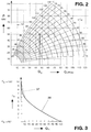
- FIG 3 shows a characteristic curve (36) of the function implemented by means of the function generator (26): Q G ⁇ ⁇ St ° / 90 ° - 2 - (sin 2 ⁇ St ) / ⁇ , where ( ⁇ St ) in degrees on the ordinate and (Q G ) in% on the abscissa.
- the ideal curve (36) can be approximated by segments (37) indicated by dashed lines and used to determine the value of the stabilization ignition angle ( ⁇ St ).
- the example shown relates to a system with an active power (P) of 60 MW with a direct current of 100 kA and an installed reactive or compensation power of 30 MVar.
Landscapes
- Engineering & Computer Science (AREA)
- Power Engineering (AREA)
- Control Of Electrical Variables (AREA)
- Supply And Distribution Of Alternating Current (AREA)
- Chemical Or Physical Treatment Of Fibers (AREA)
- Emergency Protection Circuit Devices (AREA)
Applications Claiming Priority (2)
| Application Number | Priority Date | Filing Date | Title |
|---|---|---|---|
| DE4327894A DE4327894A1 (de) | 1993-08-19 | 1993-08-19 | Verfahren zur Stabilisierung eines Stromnetzes gegen Blindlastschwankungen und Blindleistungskompensationseinrichtung |
| DE4327894 | 1993-08-19 |
Publications (4)
| Publication Number | Publication Date |
|---|---|
| EP0639880A2 true EP0639880A2 (fr) | 1995-02-22 |
| EP0639880A3 EP0639880A3 (fr) | 1995-12-13 |
| EP0639880B1 EP0639880B1 (fr) | 1997-10-22 |
| EP0639880B2 EP0639880B2 (fr) | 2001-01-24 |
Family
ID=6495546
Family Applications (1)
| Application Number | Title | Priority Date | Filing Date |
|---|---|---|---|
| EP94111523A Expired - Lifetime EP0639880B2 (fr) | 1993-08-19 | 1994-07-23 | Méthode de stabilisation d'un réseau vis à vis des oscillations d'énergie réactive et appareil de compensation d'énergie réactive |
Country Status (9)
| Country | Link |
|---|---|
| US (1) | US5627454A (fr) |
| EP (1) | EP0639880B2 (fr) |
| JP (1) | JPH07170664A (fr) |
| CN (1) | CN1041779C (fr) |
| AT (1) | ATE159626T1 (fr) |
| BR (1) | BR9403274A (fr) |
| DE (2) | DE4327894A1 (fr) |
| ES (1) | ES2111216T5 (fr) |
| RU (1) | RU2126580C1 (fr) |
Cited By (2)
| Publication number | Priority date | Publication date | Assignee | Title |
|---|---|---|---|---|
| EP0707369A1 (fr) * | 1994-10-12 | 1996-04-17 | ABB Management AG | Système pour stabiliser un réseau électrique contre les fluctuations d'une charge réactive et dispositif de compensation de puissance réactive |
| DE19623540C1 (de) * | 1996-06-13 | 1997-12-18 | Asea Brown Boveri | Verfahren zur Stabilisierung eines Wechselstromnetzes gegen Blindleistungsschwankungen und Blindleistungskompensationseinrichtung |
Families Citing this family (20)
| Publication number | Priority date | Publication date | Assignee | Title |
|---|---|---|---|---|
| DE19617191C2 (de) * | 1996-04-29 | 1998-07-16 | Siemens Ag | Einrichtung zur Gleichstromversorgung für einen Gleichstromlichtbogenofen |
| SE510197C2 (sv) * | 1997-02-06 | 1999-04-26 | Asea Brown Boveri | Förfarande och anordning för styrning av ett kondensatordon för en shuntkopplad statisk kompensatorenhet med deblockeringssignaler för indikering av icke strömförande tillstånd hos ingående ventiler |
| DE19920049C2 (de) * | 1999-04-23 | 2001-10-11 | Sms Demag Ag | Verfahren und Vorrichtung zur Stromversorgung eines über einen Lichtbogen betriebenen Schmelzaggregates |
| US6411643B1 (en) | 1999-09-30 | 2002-06-25 | Sms Demag, Inc | Automatic electrode regulator based on direct power factor regulation and method |
| US6226313B1 (en) * | 1999-10-18 | 2001-05-01 | Manoharan Thamodharan | Power source circuit and its control for three-phase electric arc furnace to reduce flicker |
| DE102005051232A1 (de) * | 2005-10-26 | 2007-05-03 | Sms Demag Ag | Steuervorrichtung für Wechselstrom-Reduktionsöfen |
| RU2390902C1 (ru) * | 2008-12-29 | 2010-05-27 | Игорь Владимирович Устименко | Способ повышения качества электрической энергии многофазной системы при симметрировании токов по одной из фаз |
| RU2382470C1 (ru) * | 2008-12-29 | 2010-02-20 | Игорь Владимирович Устименко | Способ повышения качества электрической энергии многофазной системы при симметрировании токов по заданной фазе и комбинированном отборе мощности |
| RU2382467C1 (ru) * | 2008-12-29 | 2010-02-20 | Игорь Владимирович Устименко | Способ повышения качества электрической энергии многофазной системы при симметрировании токов по заданной фазе |
| RU2382471C1 (ru) * | 2008-12-29 | 2010-02-20 | Игорь Владимирович Устименко | Способ повышения качества электрической энергии многофазной системы при симметрировании токов по одной из фаз и комбинированном отборе мощности |
| AU2009341480B2 (en) * | 2009-03-06 | 2015-09-17 | Abb Technology Ag | Poly-phase reactive power compensator |
| US20120314728A1 (en) * | 2011-06-08 | 2012-12-13 | Warner Power Llc | System and method to deliver and control power to an arc furnace |
| DE102013224736B4 (de) | 2012-12-21 | 2025-02-13 | Schäfer Elektronik Gmbh | Vorrichtung zur Korrektur von Wechselströmen |
| CN103762603A (zh) * | 2014-01-23 | 2014-04-30 | 安徽华正电气有限公司 | 一种双向无功调节电压的装置 |
| DE102014206008A1 (de) * | 2014-03-31 | 2015-10-01 | Siemens Aktiengesellschaft | Vorrichtung und Verfahren zur dynamischen Einstellung eines Elektrolichtbogenofens |
| IT201800004846A1 (it) * | 2018-04-24 | 2019-10-24 | Metodo di alimentazione elettrica di un forno elettrico ad arco e relativo apparato | |
| RU2741061C1 (ru) * | 2020-06-11 | 2021-01-22 | Федеральное государственное бюджетное образовательное учреждение высшего образования «Магнитогорский государственный технический университет им. Г. И. Носова» (ФГБОУ ВО «МГТУ им. Г.И. Носова») | Система управления многоуровневым активным фильтром |
| CN114740296B (zh) * | 2021-08-18 | 2024-08-09 | 广州晓云智慧科技有限公司 | 一种功率因数补偿设备工作状况监测方法 |
| CN115441477B (zh) * | 2022-09-29 | 2025-09-02 | 武汉大学 | 一种储能参与的高比例风电系统失步振荡抑制方法 |
| LV15892A (lv) * | 2023-04-11 | 2024-10-20 | Kopils Leonids | Līdzstrāvas elektriskā loka materiālu kausēšanas krāsns sistēma un paņēmiens |
Family Cites Families (15)
| Publication number | Priority date | Publication date | Assignee | Title |
|---|---|---|---|---|
| CA713213A (en) * | 1960-09-09 | 1965-07-06 | The General Electric Company Limited | Voltage regulating apparatus |
| AT289258B (de) * | 1967-08-11 | 1971-04-13 | Wiener Schwachstromwerke Gmbh | Hilfseinrichtung für symmetrische oder unsymmetrische Wirk- und bzw. oder Blindleistungsverbraucher |
| FR2266347B1 (fr) * | 1974-03-27 | 1982-07-02 | Siemens Ag | |
| SU558349A1 (ru) * | 1975-08-07 | 1977-05-15 | Московский Ордена Ленина Энергетический Институт | Регулируема конденсаторна батаре и способ управлени ею |
| SU754567A1 (ru) * | 1978-03-13 | 1980-08-07 | Vasilij E Klimenko | Регулятор коэффициента мощности 1 |
| DE3002373A1 (de) * | 1980-01-23 | 1981-07-30 | Siemens AG, 1000 Berlin und 8000 München | Verfahren zur minderung der netzrueckwirkungen eines netzgefuehrten direktumrichters und steuerschaltung hierzu |
| DE3708468A1 (de) * | 1986-03-17 | 1987-09-24 | Siemens Ag | Verfahren und vorrichtung zum kompensieren von oberschwingungsbelastungen und/oder blindlast in einem versorgungsnetz |
| US4752736A (en) * | 1986-07-22 | 1988-06-21 | The Regents Of The University Of California | Center fed QD MRI RF coil |
| JPS6366617A (ja) * | 1986-09-09 | 1988-03-25 | Toshiba Corp | 無効電力補償装置 |
| SU1718328A1 (ru) * | 1988-06-17 | 1992-03-07 | Тольяттинский политехнический институт | Трехфазное комбинированное фильтрокомпенсирующее устройство |
| DE3915213A1 (de) * | 1989-05-05 | 1990-11-08 | Licentia Gmbh | Anordnung zur modifizierung der strangblindleistungs-sollwerte einer m-phasigen blindleistungs-kompensationsanlage mit eingeschraenktem leistungsstellvermoegen |
| US5155740A (en) * | 1990-10-22 | 1992-10-13 | Nkk Corporation | Flicker compensating apparatus for DC arc furnace |
| DE69022854T2 (de) * | 1990-10-31 | 1996-05-02 | Nippon Kokan Kk | Einrichtung zur Flimmerkompensation für einen Gleichstromlichtbogenofen. |
| CA2060006A1 (fr) * | 1991-02-08 | 1992-08-09 | Eduard Strebel | Procede et dispositif de commande des electrodes pour four a arc a courant continu |
| DE4309640A1 (de) * | 1993-03-25 | 1994-09-29 | Abb Management Ag | Gleichstrom-Lichtbogenofenanlage |
-
1993
- 1993-08-19 DE DE4327894A patent/DE4327894A1/de not_active Withdrawn
-
1994
- 1994-07-23 DE DE59404405T patent/DE59404405D1/de not_active Expired - Fee Related
- 1994-07-23 AT AT94111523T patent/ATE159626T1/de not_active IP Right Cessation
- 1994-07-23 ES ES94111523T patent/ES2111216T5/es not_active Expired - Lifetime
- 1994-07-23 EP EP94111523A patent/EP0639880B2/fr not_active Expired - Lifetime
- 1994-08-02 US US08/284,109 patent/US5627454A/en not_active Expired - Fee Related
- 1994-08-10 JP JP6188469A patent/JPH07170664A/ja active Pending
- 1994-08-18 RU RU94030241A patent/RU2126580C1/ru active
- 1994-08-18 BR BR9403274A patent/BR9403274A/pt not_active IP Right Cessation
- 1994-08-19 CN CN94108571A patent/CN1041779C/zh not_active Expired - Fee Related
Cited By (5)
| Publication number | Priority date | Publication date | Assignee | Title |
|---|---|---|---|---|
| EP0707369A1 (fr) * | 1994-10-12 | 1996-04-17 | ABB Management AG | Système pour stabiliser un réseau électrique contre les fluctuations d'une charge réactive et dispositif de compensation de puissance réactive |
| US5617447A (en) * | 1994-10-12 | 1997-04-01 | Abb Management Ag | Method of stabilizing a power supply network against reactive load fluctuations, and a reactive power compensation device |
| DE19623540C1 (de) * | 1996-06-13 | 1997-12-18 | Asea Brown Boveri | Verfahren zur Stabilisierung eines Wechselstromnetzes gegen Blindleistungsschwankungen und Blindleistungskompensationseinrichtung |
| EP0813284A3 (fr) * | 1996-06-13 | 1998-05-20 | Asea Brown Boveri AG | Procédé pour la stabilisation d'un réseau de courant alternatif contre les oscillations de la puissance réactive et appareil pour la compensation de la puissance réactive |
| US5809054A (en) * | 1996-06-13 | 1998-09-15 | Concast Standard Ag | Method for stabilizing an AC system against reactive-load fluctuations, and a power-factor correction device |
Also Published As
| Publication number | Publication date |
|---|---|
| ES2111216T5 (es) | 2001-05-16 |
| US5627454A (en) | 1997-05-06 |
| RU2126580C1 (ru) | 1999-02-20 |
| EP0639880B1 (fr) | 1997-10-22 |
| DE4327894A1 (de) | 1995-02-23 |
| BR9403274A (pt) | 1995-04-11 |
| CN1041779C (zh) | 1999-01-20 |
| EP0639880A3 (fr) | 1995-12-13 |
| DE59404405D1 (de) | 1997-11-27 |
| RU94030241A (ru) | 1996-06-10 |
| ES2111216T3 (es) | 1998-03-01 |
| JPH07170664A (ja) | 1995-07-04 |
| EP0639880B2 (fr) | 2001-01-24 |
| ATE159626T1 (de) | 1997-11-15 |
| CN1100239A (zh) | 1995-03-15 |
Similar Documents
| Publication | Publication Date | Title |
|---|---|---|
| EP0639880B1 (fr) | Méthode de stabilisation d'un réseau vis à vis des oscillations d'énergie réactive et appareil de compensation d'énergie réactive | |
| EP0707369B1 (fr) | Système pour stabiliser un réseau électrique contre les fluctuations d'une charge réactive et dispositif de compensation de puissance réactive | |
| DE4200329C2 (de) | Regelbare Speisestromquelle | |
| EP0498239B1 (fr) | Procédé et appareil de commande d'une électrode d'un four à arc à courant continu | |
| DE19623540C1 (de) | Verfahren zur Stabilisierung eines Wechselstromnetzes gegen Blindleistungsschwankungen und Blindleistungskompensationseinrichtung | |
| DE69022854T2 (de) | Einrichtung zur Flimmerkompensation für einen Gleichstromlichtbogenofen. | |
| EP0571642A1 (fr) | Procédé et dispositif d'obtention d'un signal de synchronisation pour un étage de commande d'une soupape commandée d'un compensateur série commandé | |
| EP3513625B1 (fr) | Four à arc électrique alimenté par onduleur avec système de condensateurs dans le circuit secondaire | |
| EP0043146A1 (fr) | Procédé pour mettre en service l'un de plusieurs groupes de redresseurs montés en série d'une installation de transmission haute tension à courant continu | |
| EP1808049A1 (fr) | Dispositif de commande pour des fours de réduction à courant alternatif | |
| EP0660647A1 (fr) | Procédé de régulation pour un four à arc à courant continu | |
| EP0492414B1 (fr) | Source de courant ainsi que méthode de commande | |
| EP0571643B1 (fr) | Procédé et dispositif de commande symétrique d'une installation de compensation série | |
| DE19605419B4 (de) | Verfahren zur Beseitigung von Abweichungen der Ist-Spannung in einem Drehstromnetz von einer vorgegebenen Soll-Spannung | |
| EP0180966B1 (fr) | Onduleur avec une charge qui force la tension de sortie de l'onduleur à une fréquence et une tension déterminée | |
| EP0562471B1 (fr) | Procédé pour l'excitation des valves de deux ou plus convertisseurs avec des circuits oscillants parallèles alimentés d'un courant continu d'une source commune chaque convertisseur muni avec un four à induction chaque fois et un arrangement pour l'exécution du procédé | |
| EP0171617B1 (fr) | Méthode et dispositif pour l'exploitation d'un convertisseur indirect avec limitation de la montée de courant | |
| AT301692B (de) | Wechselrichter | |
| DE3223655A1 (de) | Einrichtung zur regelung eines wechselstrom-induktionsmotors | |
| DE4135059A1 (de) | Vorrichtung zur kontinuierlichen spannungssteuerung | |
| DE2315240C3 (de) | Verfahren und Anordnung zur Regelung des Laststromes eines Drehstrom-Wechselstrom-Direktumrichters | |
| DE2609285A1 (de) | Verfahren und anordnung zur steuerung und regelung einer stromrichter-folgeschaltung | |
| DE19817305A1 (de) | Umrichter und Verfahren zu dessen Steuerung | |
| DE3442417A1 (de) | Regeleinrichtung fuer einen direkt beheizten ofen | |
| DD231918A1 (de) | Verfahren zum energetisch angepassten betrieb von gleichstromlichtboegen |
Legal Events
| Date | Code | Title | Description |
|---|---|---|---|
| PUAI | Public reference made under article 153(3) epc to a published international application that has entered the european phase |
Free format text: ORIGINAL CODE: 0009012 |
|
| AK | Designated contracting states |
Kind code of ref document: A2 Designated state(s): AT DE ES FR IT PT |
|
| PUAL | Search report despatched |
Free format text: ORIGINAL CODE: 0009013 |
|
| AK | Designated contracting states |
Kind code of ref document: A3 Designated state(s): AT DE ES FR IT PT |
|
| 17P | Request for examination filed |
Effective date: 19960504 |
|
| 17Q | First examination report despatched |
Effective date: 19960905 |
|
| RAP1 | Party data changed (applicant data changed or rights of an application transferred) |
Owner name: ASEA BROWN BOVERI AG |
|
| GRAG | Despatch of communication of intention to grant |
Free format text: ORIGINAL CODE: EPIDOS AGRA |
|
| GRAH | Despatch of communication of intention to grant a patent |
Free format text: ORIGINAL CODE: EPIDOS IGRA |
|
| GRAH | Despatch of communication of intention to grant a patent |
Free format text: ORIGINAL CODE: EPIDOS IGRA |
|
| GRAA | (expected) grant |
Free format text: ORIGINAL CODE: 0009210 |
|
| AK | Designated contracting states |
Kind code of ref document: B1 Designated state(s): AT DE ES FR IT PT |
|
| REF | Corresponds to: |
Ref document number: 159626 Country of ref document: AT Date of ref document: 19971115 Kind code of ref document: T |
|
| REF | Corresponds to: |
Ref document number: 59404405 Country of ref document: DE Date of ref document: 19971127 |
|
| ITF | It: translation for a ep patent filed | ||
| ET | Fr: translation filed | ||
| REG | Reference to a national code |
Ref country code: ES Ref legal event code: FG2A Ref document number: 2111216 Country of ref document: ES Kind code of ref document: T3 |
|
| REG | Reference to a national code |
Ref country code: PT Ref legal event code: SC4A Free format text: AVAILABILITY OF NATIONAL TRANSLATION Effective date: 19980121 |
|
| PLBQ | Unpublished change to opponent data |
Free format text: ORIGINAL CODE: EPIDOS OPPO |
|
| PLBI | Opposition filed |
Free format text: ORIGINAL CODE: 0009260 |
|
| PLBF | Reply of patent proprietor to notice(s) of opposition |
Free format text: ORIGINAL CODE: EPIDOS OBSO |
|
| 26 | Opposition filed |
Opponent name: CEGELEC AEG ANLAGEN UND ANTRIEBSSYSTEME GMBH Effective date: 19980722 |
|
| PLBF | Reply of patent proprietor to notice(s) of opposition |
Free format text: ORIGINAL CODE: EPIDOS OBSO |
|
| PLAB | Opposition data, opponent's data or that of the opponent's representative modified |
Free format text: ORIGINAL CODE: 0009299OPPO |
|
| PLAW | Interlocutory decision in opposition |
Free format text: ORIGINAL CODE: EPIDOS IDOP |
|
| R26 | Opposition filed (corrected) |
Opponent name: ALSTOM ANLAGEN UND ANTRIEBSYSTEME GMBH Effective date: 19980722 |
|
| PGFP | Annual fee paid to national office [announced via postgrant information from national office to epo] |
Ref country code: ES Payment date: 20000720 Year of fee payment: 7 |
|
| PLAW | Interlocutory decision in opposition |
Free format text: ORIGINAL CODE: EPIDOS IDOP |
|
| PUAH | Patent maintained in amended form |
Free format text: ORIGINAL CODE: 0009272 |
|
| STAA | Information on the status of an ep patent application or granted ep patent |
Free format text: STATUS: PATENT MAINTAINED AS AMENDED |
|
| RAP2 | Party data changed (patent owner data changed or rights of a patent transferred) |
Owner name: ABB INDUSTRIE AG |
|
| 27A | Patent maintained in amended form |
Effective date: 20010124 |
|
| AK | Designated contracting states |
Kind code of ref document: B2 Designated state(s): AT DE ES FR IT PT |
|
| ITF | It: translation for a ep patent filed | ||
| REG | Reference to a national code |
Ref country code: ES Ref legal event code: DC2A Kind code of ref document: T5 Effective date: 20010420 |
|
| ET3 | Fr: translation filed ** decision concerning opposition | ||
| PGFP | Annual fee paid to national office [announced via postgrant information from national office to epo] |
Ref country code: PT Payment date: 20010622 Year of fee payment: 8 |
|
| PGFP | Annual fee paid to national office [announced via postgrant information from national office to epo] |
Ref country code: AT Payment date: 20010704 Year of fee payment: 8 |
|
| PGFP | Annual fee paid to national office [announced via postgrant information from national office to epo] |
Ref country code: FR Payment date: 20010709 Year of fee payment: 8 |
|
| PGFP | Annual fee paid to national office [announced via postgrant information from national office to epo] |
Ref country code: DE Payment date: 20010713 Year of fee payment: 8 |
|
| REG | Reference to a national code |
Ref country code: PT Ref legal event code: PD4A Free format text: ABB INDUSTRIE AG CH Effective date: 20010424 |
|
| PG25 | Lapsed in a contracting state [announced via postgrant information from national office to epo] |
Ref country code: AT Free format text: LAPSE BECAUSE OF NON-PAYMENT OF DUE FEES Effective date: 20020723 |
|
| PG25 | Lapsed in a contracting state [announced via postgrant information from national office to epo] |
Ref country code: ES Free format text: LAPSE BECAUSE OF NON-PAYMENT OF DUE FEES Effective date: 20020724 |
|
| PG25 | Lapsed in a contracting state [announced via postgrant information from national office to epo] |
Ref country code: PT Free format text: LAPSE BECAUSE OF NON-PAYMENT OF DUE FEES Effective date: 20030131 |
|
| PG25 | Lapsed in a contracting state [announced via postgrant information from national office to epo] |
Ref country code: DE Free format text: LAPSE BECAUSE OF NON-PAYMENT OF DUE FEES Effective date: 20030201 |
|
| PG25 | Lapsed in a contracting state [announced via postgrant information from national office to epo] |
Ref country code: FR Free format text: LAPSE BECAUSE OF NON-PAYMENT OF DUE FEES Effective date: 20030331 |
|
| REG | Reference to a national code |
Ref country code: PT Ref legal event code: MM4A Free format text: LAPSE DUE TO NON-PAYMENT OF FEES Effective date: 20030131 |
|
| REG | Reference to a national code |
Ref country code: FR Ref legal event code: ST |
|
| REG | Reference to a national code |
Ref country code: ES Ref legal event code: FD2A Effective date: 20030811 |
|
| PG25 | Lapsed in a contracting state [announced via postgrant information from national office to epo] |
Ref country code: IT Free format text: LAPSE BECAUSE OF NON-PAYMENT OF DUE FEES;WARNING: LAPSES OF ITALIAN PATENTS WITH EFFECTIVE DATE BEFORE 2007 MAY HAVE OCCURRED AT ANY TIME BEFORE 2007. THE CORRECT EFFECTIVE DATE MAY BE DIFFERENT FROM THE ONE RECORDED. Effective date: 20050723 |
|
| PLAB | Opposition data, opponent's data or that of the opponent's representative modified |
Free format text: ORIGINAL CODE: 0009299OPPO |