EP0063760A1 - Méthode et dispositif pour tester les surfaces intérieures de réservoirs ronds - Google Patents
Méthode et dispositif pour tester les surfaces intérieures de réservoirs ronds Download PDFInfo
- Publication number
- EP0063760A1 EP0063760A1 EP82103213A EP82103213A EP0063760A1 EP 0063760 A1 EP0063760 A1 EP 0063760A1 EP 82103213 A EP82103213 A EP 82103213A EP 82103213 A EP82103213 A EP 82103213A EP 0063760 A1 EP0063760 A1 EP 0063760A1
- Authority
- EP
- European Patent Office
- Prior art keywords
- mirror
- light
- scanning
- rotating
- container
- Prior art date
- Legal status (The legal status is an assumption and is not a legal conclusion. Google has not performed a legal analysis and makes no representation as to the accuracy of the status listed.)
- Withdrawn
Links
- 238000012360 testing method Methods 0.000 title claims abstract description 34
- 238000000034 method Methods 0.000 title claims description 15
- 230000007547 defect Effects 0.000 claims abstract description 10
- 238000011156 evaluation Methods 0.000 claims description 11
- 235000013361 beverage Nutrition 0.000 claims description 6
- 239000004922 lacquer Substances 0.000 claims description 5
- 238000010422 painting Methods 0.000 claims description 4
- 230000002950 deficient Effects 0.000 claims description 3
- 230000003287 optical effect Effects 0.000 claims description 2
- 238000011144 upstream manufacturing Methods 0.000 claims 1
- 239000003973 paint Substances 0.000 abstract description 9
- 230000005855 radiation Effects 0.000 abstract description 5
- 238000000149 argon plasma sintering Methods 0.000 description 4
- 239000011248 coating agent Substances 0.000 description 4
- 238000000576 coating method Methods 0.000 description 4
- 230000004888 barrier function Effects 0.000 description 3
- 239000000463 material Substances 0.000 description 3
- 229910052751 metal Inorganic materials 0.000 description 3
- 239000002184 metal Substances 0.000 description 3
- CURLTUGMZLYLDI-UHFFFAOYSA-N Carbon dioxide Chemical compound O=C=O CURLTUGMZLYLDI-UHFFFAOYSA-N 0.000 description 2
- 239000002253 acid Substances 0.000 description 2
- 239000003086 colorant Substances 0.000 description 2
- 238000013461 design Methods 0.000 description 2
- 230000004069 differentiation Effects 0.000 description 2
- 238000007689 inspection Methods 0.000 description 2
- 238000007591 painting process Methods 0.000 description 2
- 239000011148 porous material Substances 0.000 description 2
- ATJFFYVFTNAWJD-UHFFFAOYSA-N Tin Chemical compound [Sn] ATJFFYVFTNAWJD-UHFFFAOYSA-N 0.000 description 1
- 150000007513 acids Chemical class 0.000 description 1
- 229910052782 aluminium Inorganic materials 0.000 description 1
- XAGFODPZIPBFFR-UHFFFAOYSA-N aluminium Chemical compound [Al] XAGFODPZIPBFFR-UHFFFAOYSA-N 0.000 description 1
- 235000013405 beer Nutrition 0.000 description 1
- 229910002092 carbon dioxide Inorganic materials 0.000 description 1
- 239000001569 carbon dioxide Substances 0.000 description 1
- 238000010276 construction Methods 0.000 description 1
- 230000006735 deficit Effects 0.000 description 1
- 230000001419 dependent effect Effects 0.000 description 1
- 238000001514 detection method Methods 0.000 description 1
- 235000013399 edible fruits Nutrition 0.000 description 1
- 230000002349 favourable effect Effects 0.000 description 1
- 238000001914 filtration Methods 0.000 description 1
- 235000013305 food Nutrition 0.000 description 1
- 229910052736 halogen Inorganic materials 0.000 description 1
- 150000002367 halogens Chemical class 0.000 description 1
- 230000001771 impaired effect Effects 0.000 description 1
- 229910052500 inorganic mineral Inorganic materials 0.000 description 1
- 235000015122 lemonade Nutrition 0.000 description 1
- 238000012423 maintenance Methods 0.000 description 1
- 238000004519 manufacturing process Methods 0.000 description 1
- 239000011707 mineral Substances 0.000 description 1
- 238000004806 packaging method and process Methods 0.000 description 1
- 230000000149 penetrating effect Effects 0.000 description 1
- 239000000523 sample Substances 0.000 description 1
- 235000014214 soft drink Nutrition 0.000 description 1
- 239000007921 spray Substances 0.000 description 1
- 238000005507 spraying Methods 0.000 description 1
- 239000000126 substance Substances 0.000 description 1
- 239000005028 tinplate Substances 0.000 description 1
- 239000002966 varnish Substances 0.000 description 1
- 238000011179 visual inspection Methods 0.000 description 1
- XLYOFNOQVPJJNP-UHFFFAOYSA-N water Substances O XLYOFNOQVPJJNP-UHFFFAOYSA-N 0.000 description 1
Images

Classifications
-
- G—PHYSICS
- G01—MEASURING; TESTING
- G01N—INVESTIGATING OR ANALYSING MATERIALS BY DETERMINING THEIR CHEMICAL OR PHYSICAL PROPERTIES
- G01N21/00—Investigating or analysing materials by the use of optical means, i.e. using sub-millimetre waves, infrared, visible or ultraviolet light
- G01N21/84—Systems specially adapted for particular applications
- G01N21/88—Investigating the presence of flaws or contamination
- G01N21/90—Investigating the presence of flaws or contamination in a container or its contents
- G01N21/909—Investigating the presence of flaws or contamination in a container or its contents in opaque containers or opaque container parts, e.g. cans, tins, caps, labels
-
- G—PHYSICS
- G01—MEASURING; TESTING
- G01N—INVESTIGATING OR ANALYSING MATERIALS BY DETERMINING THEIR CHEMICAL OR PHYSICAL PROPERTIES
- G01N33/00—Investigating or analysing materials by specific methods not covered by groups G01N1/00 - G01N31/00
- G01N33/0078—Testing material properties on manufactured objects
- G01N33/0081—Containers; Packages; Bottles
Definitions
- the invention relates to a method and a device for checking the surfaces of round containers, such as food and beverage cans, for surface defects, in particular defective interior painting.
- Beverage cans in particular cans for soft drinks, such as carbonated mineral water and lemonades, but also beer, are filled into different types of cans.
- One type of can is deep-drawn cans with inwardly curved or flat bottoms; another can shape corresponds to the usual tin can, ie it consists of a folded, possibly welded or soldered jacket with a flanged bottom.
- Tinplate is generally used as the material for the cans; some also consist of Aluminum sheet.
- all materials have in common that they must not come into direct contact with acids, such as those present in the form of carbon dioxide or fruit acid in drinks, since these substances attack the metal and thereby change the taste of the packaged goods, thereby spoiling the goods can, but also the packaging is impaired. The latter point can go so far that the packaged good eats through the can and exits through pores.
- the cans are painted, which is done in machines because of the high number of pieces.
- the cans have generally been checked visually when the cans are packaged to ensure they are in perfect condition. There is no absolute guarantee that every paint defect will be recorded, since with such mass products, a precise visual inspection, which requires the can to be rotated around its own axis and thus all parts of the wall to be viewed, is too complex.
- the alternative way of producing cans is to first coat the sheet and then deep-draw this coated sheet.
- the coating that is to say the paint, is subject to even higher demands since it has to deform with the sheet metal. Consequently, both sheet metal and paint damage also occur here, which have to be detected and sorted out.
- This object is achieved by a method for checking the surfaces of round containers, such as cans and beverage cans, for surface defects, in particular for defective interior painting, with the characteristic feature that a light beam is directed onto a rotating mirror, which is then shaped into a scanning circle, the diameter of the scanning circle essentially corresponds to the diameter of the container, the light beam reflects from the bottom and / or the container wall and the reflected light is directed to a photo converter, which supplies pulses to an evaluation station.
- the use of a light beam and the use of a rotating mirror result in extremely high scanning speeds, such as are required for testing bulk goods.
- the mirror creates a rotating light spot which forms a scanning circle in the test plane, the line width of this scanning circle being dependent on the diameter of the light spot.
- the finer the point of light the higher the intensity, the more precise can so that even small defects in the coating can be detected.
- the scanning circle diameter is slightly smaller than the inside diameter of the container so that the scanning beam does not trigger error signals by deflection at the bottom edges of the container without the container having an error.
- the light thrown back from the container reaches a photo converter, expediently a photo detector, which converts it into pulses corresponding to the light brightness and passes these pulses on to an evaluation station.
- an expedient embodiment of the invention provides that the test is carried out with a laser beam.
- Laser emitters emit a practically parallel light, so that no optical means for focusing a light spot are required. They also have a practically constant light intensity over their lifetime, so that units for readjusting the brightness can be omitted.
- a preferred embodiment of the invention provides that the laser emitter emits rays with a wavelength of 4oo to 53o NM, ie emits in the colors blue and / or green. This radiation stimulates fluorescence in the lacquer layer of all conventional lacquers used for the interior lacquering of containers. The same fluorescence would also be achieved with a UV laser, but the efficiency of the UV laser is very low, so its use should be reserved for special purposes.
- fluorescence only occurs where the laser beam hits painted surfaces. This results in a higher luminous efficacy in these areas, so that a better differentiation between the faulty location, i.e. unpainted spot and flawless spot in the container.
- the cheapest evaluation option results if, according to a particularly advantageous embodiment of the invention, only the fluorescent light is evaluated.
- the directly reflected part of the laser radiation must be filtered out, so that only the diffuse light component falls into the photo converter. In practical evaluation this means that an unpainted can generates no light signal at all, whereas partially lacquered cans do not generate any light signals in the corresponding areas.
- An expedient embodiment of the invention provides that the containers to be tested are continuously fed to a test device and aligned in their position below this.
- the feed can be done by a practice Liche conveyor line, for example in the form of a conveyor belt, with a parallel alignment first, so that the cans to be tested in a row are continuously performed under the test device.
- a practice Liche conveyor line for example in the form of a conveyor belt
- a parallel alignment first so that the cans to be tested in a row are continuously performed under the test device.
- the scanning cycle only takes 2 milliseconds at the high speed of 30,000 revolutions of the rotating mirror, that is to say practically only a snapshot of the container in motion, the container movement does not interfere with the test, since it also affects the number of looo cans per minute, compared to the scanning speed, is too slow to lead to erroneous results.
- a preferred embodiment of the invention provides that the size of the circle diameter of the scanning circle can be selected. This selectability is of great importance because cans with different diameters are produced, but it is useful to be able to scan and check as many diameters as possible with one and the same unit.
- the simplest way to change the diameter of the scanning circle is to increase or decrease the distance between the mirror and the container. This option will always be chosen if there are no large differences in the diameters, the large differences in distance cause and thus lead to significant changes in the light intensity.
- annular area of the base and an annular area of the can body are checked for the container to be tested.
- the explanation for this is to be found in the painting process, which takes place in such a way that each can rotates around its own longitudinal axis and, during this rotation, a spray tube with nozzles sinks into the can.
- the floor is sprayed through a nozzle, and the fuselage, that is the wall of the can, is sprayed through another, so that only a few errors can result from this painting process.
- the first error that resulted was that no paint was added to the nozzle, i.e. no spraying at all.
- the second mistake is a nozzle clog.
- An advantageous embodiment of the invention therefore provides that the width of the scanning circle is adjustable.
- the scanning is therefore expediently carried out with a transverse stretch of light.
- the line width of the scanning circle is more or less large, and the fact that the light line as such is kept very narrow also maintains the necessary light intensity.
- a preferred device for carrying out the method consists essentially of a conveyor line with a measuring head arranged above it, a photo converter and an evaluation device and has the characteristic feature that the measuring head contains a radiator to which a rotating, inclined mirror is assigned.
- Point-shaped light sources such as halogen lamps are suitable as spotlights.
- laser emitters are expediently used because they already bundle the beam, which emerges essentially in parallel and therefore does not require any optics for bundling and generating a light spot on the rotating mirror.
- the rotating mirror as such is relatively small because it only has to redirect one point of light.
- the rotational speed of the rotating mirror is 3,000 to 30,000 revolutions per minute.
- the high speeds allow the conveyor line to run at high speed and thus large quantities enforce as is desired for bulk goods.
- a preferred embodiment of the invention provides that the end face of the rotor shaft of a motor is designed as an oblique mirror.
- the end face of the rotor shaft can be directly mirrored, but a mirror can also be applied to this surface, which is then adjusted in the required inclination to achieve a certain scanning circle size.
- it is necessary that the light point generated by the spotlight is directed via mirrors or prisms onto the inclined mirror before it can be deflected by them to the circular line.
- a convenient alternative solution provides that the rotating mirror within the rotor shaft of a motor s-forming tube is disposed. Since the rotating, inclined mirror has only small dimensions, there is the possibility of arranging it within a tube with a small diameter and thus avoiding the effort for prisms or mirrors to redirect the light point to the mirror. In this case, it is sufficient to arrange the spotlight directly above the motor, so that it radiates directly into the rotor shaft of the motor and depicts the light spot on the mirror.
- An advantageous embodiment of the invention provides that the motor is closed by a mirrored, light-scattering disc Surrounded space, which is assigned a photo converter.
- the motor forms the central part of the measuring head, through which the radiation reaches the outside. Since it has no driving function, it must be dimensioned very small, so that the space surrounding it in the measuring head is fully available for holding measuring units.
- the combination of mirroring this space, which surrounds in, on all sides, except for the side facing the test object, and at the same time closing it off with a light-scattering pane makes it possible to convert the light directly reflected by the test object into diffuse light, which means the detection of errors on high-gloss, specular specimens and at the same time collect diffuse emitted light and feed it to the photo converter. By avoiding the entry of directly reflected light, the photo converter is not overloaded, ie peaks that could lead to an overload of the unit are avoided.
- a preferred embodiment of the invention provides that the rotating mirror is assigned a stationary mirror which surrounds it in a ring.
- the stationary mirror can expediently be a conical ring.
- the design as a parabolic mirror is also advantageous.
- Both the design as a conical ring and as a parabolic mirror enables a very simple change of the scanning circle diameter.
- the mirror e is enlarged or reduced in the scanning circle, ie the diameter can be changed very quickly.
- the arrangement of a stationary, ring-shaped mirror is of considerable importance, but only for the further reason that with an aggregate equipped in this way, by assigning a further stationary, ring-shaped mirror, in addition to the internal scanning of the cans, an external scanning of the can body can also take place.
- the conical ring or the parabolic mirror enable the generation of a scanning beam running parallel to the rotor shaft, which in this case strikes another, stationary mirror field and from there almost perpendicularly to the test specimen. If the beam is already deformed into a transversely stretched light line or has it Form of a zigzag band on how it can be generated by the use of a vibration device, the defects on the outside of the torso of the test specimen can also be detected.
- a particularly preferred embodiment of the invention provides that the photo converter is preceded by a filter which, according to a further expedient embodiment of the invention, is opaque for wavelengths below 53 nm.
- This embodiment of the invention is particularly important in connection with the use of a laser beam which emits in a wavelength of 4oo to 53o NM. This wavelength is the colors blue and / or green in the lacquer layer of the can stimulate fluorescence.
- the photomultiplier that has been converted into a fluorescent light in the lacquer layer, that is to say a light of a different wavelength, generally a wavelength of approximately 6000 nm. Defects in the varnish layer thus lead to an immediate total failure of the light point, that is, they give a very strong error signal, which enables fine error differentiation.
- an expedient embodiment of the invention provides that the mirror in its Angular position in the tube is adjustable. Due to the adjustability of the mirror, the diameter of the scanning ring can be changed with relatively simple means, without the beam path being significantly lengthened, i.e. without significant loss of light.
- the generation of a larger line width of the scanning circle to provide the mirror with a vibration device.
- the flying light line generated by the laser emitter is now rotated around its axis by rotating, and on the other by the movable mon Tiert mirrors on the vibrating device up and down by a certain amount, so that instead of a circular scan, a scan results in the form of a zigzag band, which also has a circular shape.
- the zigzag rays are close together.
- the frequency at which the mirror vibrates is expediently 10 to 100 times the speed frequency.
- a further advantageous embodiment of the invention provides that the rotating tube is followed by a pierced mirror, which is advantageously followed by a pinhole on the way to the container to be tested.
- the pierced mirror is at an oblique angle to the test object / container and enables the beam deflected by the rotating mirror to pass through the bore onto the container.
- the light reflected by this or the can body falls on the mirror due to the deflection and is directed towards the photo converter ? if necessary, with the interposition of a converging lens and a filter.
- the use of a pinhole between the pierced mirror and the container to be tested allows that only the diffusely reflected light is evaluated direct / reflected e so it can be hidden. This device is particularly important in the case of highly reflective material, because it avoids the fact that the photo converter has to take up differences in similarities that are too great.
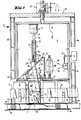
- the test specimen 12 is guided under the measuring head 2, which is connected to the evaluation device 4 via the line 14.
- the emitter 5 is arranged, which is designed as a laser emitter and throws a beam 15 onto the inclined mirror 7 in the rotating tube 6.
- the beam 15 is derived from the inclined mirror 7 as a reflected beam 15 'and passes through the bore 16 of the pierced mirror 11. After passing through the pinhole 13, the reflected beam 15' falls on the test specimen 12, which is guided by lateral guides 17, which on the Conveyor path 1 are arranged in the scanning area.
- the beam 15 'strikes the body 23 of the can and generates the scanning line 20 by rotating the rotating tube 6 together with the mirror 7.
- the beam 15' is directed onto the bottom 22 of the deflected 12 and thrown back by the latter as a directly reflected beam 15 ′′ through the bore 16 in the pierced mirror 11 from the test specimen 12.
- the paint was excited to diffuse radiation 24 which from the pierced mirror 11 through the filter 21 and the converging lens 18 to the photo converter 3. From there, a line 14 leads to the evaluation device 4. Any remaining, directly reflected light is essentially blocked out by the pinhole 13, but possibly still open the penetrating mirror 11 is absorbed by the filter 21.
- Optics 34 e.g. from a diverging and a cylindrical lens. These optics 34 stretch the beam 15 transversely to its beam travel direction, so that from the beam 15, which is punctiform in cross section, a light beam 19 or light beam plane 19 with a cross section is created. When it strikes the rotating inclined mirror 7, this light beam 19 generates a reflecting light line 35, which strikes the test specimen, here in FIG. 1, the fuselage 23 as a parallel beam plane 19 and produces a cylindrical ring-shaped light test surface 19 ′′ there.
- This light test surface can be set so large by appropriate inclination of the mirror 7 that it e.g. the entire inner surface of the fuselage 23 is coated and / or the floor 22. The entire test surface can thus be scanned.
- the measuring head as shown in FIG. 2, is equipped with a light barrier 29 which consists of the transmitter 9 and the receiver 10.
- the light barrier 29 sends pulses to the evaluation station 4, which enable counting of the tested cans.
- the reject station issues a rejection device to an evaluation unit connected to the reject device.
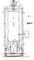
- the measuring head 2 is suspended from a vertical adjustment drive 43.
- the vertical adjustment drive rests on a cross member 45, which in turn forms the main part of a frame 44.
- Fig. 3 shows that the inclined mirror 7 is articulated at 4o in the rotating tube 6 and is acted upon by a vibration device 8, which gives the beam 15 'an additional movement, as characterized by angle ⁇ .
- the beam 15 ' now also traverses a radial movement, that is to say that instead of the scanning line 2o having a high light point, it describes a wide scanning line 2 0 ' which, as FIG. 3 shows, the area between the Center of the bottom 22 of the specimen and its upper edge 41 on the fuselage 23 covers.
- the device under test 12 is thus scanned continuously on the inside.
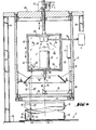
- the photo converter 3 is arranged in a space 25 which is mirrored on all sides on its inner surfaces 42 and which is covered by a light-scattering disk 26.
- the motor 27 In the mirrored room 25 there is also the motor 27, the rotor shaft 28 of which protrudes from the room 25 through the light-scattering disk 26.
- the end face 33 the motor shaft 28 is tapered and forms or carries the inclined mirror 7.
- the beam 15 'reflected by the inclined mirror 7 falls on the stationary mirror 31, which surrounds the rotor shaft 28 in the shape of a cone, and is deflected by this mirror 31 onto the test specimen 12 and forms the scanning line 47 there 3 closes down.
- the mirror 7 can now be adjusted relative to the ring mirror 31 by the vertical actuator. This provides an adjustment of the diameter 46 of the scanning line 47.
Landscapes
- Chemical & Material Sciences (AREA)
- Health & Medical Sciences (AREA)
- Life Sciences & Earth Sciences (AREA)
- General Health & Medical Sciences (AREA)
- Analytical Chemistry (AREA)
- Biochemistry (AREA)
- Physics & Mathematics (AREA)
- General Physics & Mathematics (AREA)
- Immunology (AREA)
- Pathology (AREA)
- Engineering & Computer Science (AREA)
- Food Science & Technology (AREA)
- Medicinal Chemistry (AREA)
- Investigating Materials By The Use Of Optical Means Adapted For Particular Applications (AREA)
Applications Claiming Priority (2)
| Application Number | Priority Date | Filing Date | Title |
|---|---|---|---|
| DE19813115636 DE3115636A1 (de) | 1981-04-18 | 1981-04-18 | Verfahren und vorrichtung zum pruefen der innenflaechen von runden behaeltern |
| DE3115636 | 1981-04-18 |
Publications (1)
| Publication Number | Publication Date |
|---|---|
| EP0063760A1 true EP0063760A1 (fr) | 1982-11-03 |
Family
ID=6130386
Family Applications (1)
| Application Number | Title | Priority Date | Filing Date |
|---|---|---|---|
| EP82103213A Withdrawn EP0063760A1 (fr) | 1981-04-18 | 1982-04-16 | Méthode et dispositif pour tester les surfaces intérieures de réservoirs ronds |
Country Status (2)
| Country | Link |
|---|---|
| EP (1) | EP0063760A1 (fr) |
| DE (1) | DE3115636A1 (fr) |
Cited By (5)
| Publication number | Priority date | Publication date | Assignee | Title |
|---|---|---|---|---|
| GB2174196A (en) * | 1985-04-25 | 1986-10-29 | Barry Wehmiller Ltd | Container finish inspection apparatus |
| DE19521681A1 (de) * | 1994-08-10 | 1996-02-15 | Graessle Walter Gmbh | Vorrichtung und Verfahren zur Rücknahme von Hohlkörpern |
| WO1996031767A1 (fr) * | 1995-04-05 | 1996-10-10 | Contest Marketing Ab | Dispositif de controle automatique de particules magnetiques |
| DE19940363A1 (de) * | 1999-08-25 | 2001-03-29 | Krones Ag | Vorrichtung und Verfahren zur optischen Inspektion offener Getränkebehälter |
| EP4368974A1 (fr) * | 2022-11-08 | 2024-05-15 | Krones AG | Inspection par uv pour identifier un revêtement défectueux sur le fond de la canette de boisson |
Citations (3)
| Publication number | Priority date | Publication date | Assignee | Title |
|---|---|---|---|---|
| US3150266A (en) * | 1961-02-13 | 1964-09-22 | Owens Illinois Glass Co | Inspecting interior wall surfaces of containers |
| DE1648640B2 (de) * | 1966-09-29 | 1973-12-13 | O' Connor, Bartholomew John | Vorrichtung zum Nachweis von Fremdstoffen an den Wanden eines durch scheinenden oder durchsichtigen Be halters |
| DE2910516A1 (de) * | 1979-03-16 | 1980-09-18 | Kirin Brewery | Anordnung zur feststellung von fehlern in flaschen o.dgl. |
-
1981
- 1981-04-18 DE DE19813115636 patent/DE3115636A1/de not_active Ceased
-
1982
- 1982-04-16 EP EP82103213A patent/EP0063760A1/fr not_active Withdrawn
Patent Citations (3)
| Publication number | Priority date | Publication date | Assignee | Title |
|---|---|---|---|---|
| US3150266A (en) * | 1961-02-13 | 1964-09-22 | Owens Illinois Glass Co | Inspecting interior wall surfaces of containers |
| DE1648640B2 (de) * | 1966-09-29 | 1973-12-13 | O' Connor, Bartholomew John | Vorrichtung zum Nachweis von Fremdstoffen an den Wanden eines durch scheinenden oder durchsichtigen Be halters |
| DE2910516A1 (de) * | 1979-03-16 | 1980-09-18 | Kirin Brewery | Anordnung zur feststellung von fehlern in flaschen o.dgl. |
Cited By (8)
| Publication number | Priority date | Publication date | Assignee | Title |
|---|---|---|---|---|
| GB2174196A (en) * | 1985-04-25 | 1986-10-29 | Barry Wehmiller Ltd | Container finish inspection apparatus |
| GB2174196B (en) * | 1985-04-25 | 1989-06-28 | Barry Wehmiller Ltd | Container finish inspection apparatus |
| DE19521681A1 (de) * | 1994-08-10 | 1996-02-15 | Graessle Walter Gmbh | Vorrichtung und Verfahren zur Rücknahme von Hohlkörpern |
| WO1996031767A1 (fr) * | 1995-04-05 | 1996-10-10 | Contest Marketing Ab | Dispositif de controle automatique de particules magnetiques |
| DE19940363A1 (de) * | 1999-08-25 | 2001-03-29 | Krones Ag | Vorrichtung und Verfahren zur optischen Inspektion offener Getränkebehälter |
| DE19940363C2 (de) * | 1999-08-25 | 2003-08-07 | Krones Ag | Vorrichtung und Verfahren zur optischen Inspektion offener Getränkebehälter |
| US6654116B1 (en) | 1999-08-25 | 2003-11-25 | Krones Ag Hermann Kronseder | Device and method of optical inspection of open beverage containers |
| EP4368974A1 (fr) * | 2022-11-08 | 2024-05-15 | Krones AG | Inspection par uv pour identifier un revêtement défectueux sur le fond de la canette de boisson |
Also Published As
| Publication number | Publication date |
|---|---|
| DE3115636A1 (de) | 1982-11-04 |
Similar Documents
| Publication | Publication Date | Title |
|---|---|---|
| DE3878213T2 (de) | Verfahren und vorrichtung zum pruefen eines transparenten behaelters. | |
| EP0873510B1 (fr) | Dispositif d'inspection de bouteilles et autres articles similaires | |
| DE60223956T3 (de) | Untersuchungsgerät und System zur Untersuchung von Fremdkörpern in mit Flüssigkeit gefüllten Behältern | |
| EP1079228B1 (fr) | Méthode et dispositif pour l'inspection optique de récipients à boisson ouverts | |
| DE102014217771B4 (de) | Vorrichtung und Verfahren zur Qualitätskontrolle transparenter Objekte | |
| EP0063761A1 (fr) | Méthode et dispositif pour tester des surfaces limitées par des lignes circulaires | |
| EP2885630A1 (fr) | Inspection de l'intérieur de récipients par le bas à travers le fond | |
| DE69424236T2 (de) | Prüfung von durchsichtigen Behältern | |
| EP1346205A2 (fr) | Procede et dispositif d'inspection optique de bouteilles | |
| EP1681559B1 (fr) | Procédé et dispositif pour contrôler la surface d'étanchéité de l'ouverture d' un récipient | |
| EP0063760A1 (fr) | Méthode et dispositif pour tester les surfaces intérieures de réservoirs ronds | |
| DE2415592C3 (de) | Verfahren zum Messen von Fehlstellen in einer kreisringförmigen, mit einer Dichtungsmasse versehenen Verschlußzone auf dem Boden eines rotationssymmetrischen Deckels | |
| DE19920007C1 (de) | Vorrichtung zur Inspektion von Dichtflächen an Flaschen | |
| DE29907762U1 (de) | Vorrichtung zur Untersuchung eines Behälters auf Oberflächenfehler | |
| DE1135201B (de) | Kontrolleinrichtung zur Feststellung von Fremdkoerpern in einem durch-scheinenden Behaelter mit Mitteln zur Beleuchtung einer zu kontrollierenden Zone des Behaelters | |
| EP1371944A2 (fr) | Dispositif pour contrôler l'ouverture d'un récipient par rapport à la présence d'une inclinaison | |
| DE3784989T2 (de) | Verfahren und vorrichtung zum pruefen der oberflaeche von halbleiterwafern mittels laserabtastung. | |
| DE2200092C3 (de) | Optische Lesevorrichtung zur Abtastung von Codemarken auf Gegenständen | |
| DE2100729A1 (de) | Vorrichtung zum Prüfen transparenter Behälter | |
| DE102005014596B3 (de) | Vorrichtung und Verfahren zur Inspektion der Oberfläche eines Wafers | |
| DE2411723A1 (de) | Optische pruefvorrichtung fuer behaelter | |
| EP1811288A2 (fr) | Dispositif et procédé destinés à l'inspection de fermetures de récipients | |
| DE19601114C2 (de) | Vorrichtung zur Prüfung auf Licht reflektierende Fehler | |
| DE2258702A1 (de) | Verfahren und vorrichtung zur bestimmung der lichtablenkenden eigenschaft einer transparenten zone | |
| DE3115635C2 (de) | Vorrichtung zum Prüfen der Innenflächen von Hohlkörpern |
Legal Events
| Date | Code | Title | Description |
|---|---|---|---|
| PUAI | Public reference made under article 153(3) epc to a published international application that has entered the european phase |
Free format text: ORIGINAL CODE: 0009012 |
|
| AK | Designated contracting states |
Designated state(s): AT BE CH FR GB IT LU NL SE |
|
| 17P | Request for examination filed |
Effective date: 19820915 |
|
| STAA | Information on the status of an ep patent application or granted ep patent |
Free format text: STATUS: THE APPLICATION HAS BEEN WITHDRAWN |
|
| 18W | Application withdrawn |
Withdrawal date: 19840519 |
|
| RIN1 | Information on inventor provided before grant (corrected) |
Inventor name: HAUBOLD, WOLFGANG |