EP1811288A2 - Dispositif et procédé destinés à l'inspection de fermetures de récipients - Google Patents
Dispositif et procédé destinés à l'inspection de fermetures de récipients Download PDFInfo
- Publication number
- EP1811288A2 EP1811288A2 EP06024678A EP06024678A EP1811288A2 EP 1811288 A2 EP1811288 A2 EP 1811288A2 EP 06024678 A EP06024678 A EP 06024678A EP 06024678 A EP06024678 A EP 06024678A EP 1811288 A2 EP1811288 A2 EP 1811288A2
- Authority
- EP
- European Patent Office
- Prior art keywords
- vessel
- vessels
- observation
- observation device
- moves
- Prior art date
- Legal status (The legal status is an assumption and is not a legal conclusion. Google has not performed a legal analysis and makes no representation as to the accuracy of the status listed.)
- Withdrawn
Links
- 238000000034 method Methods 0.000 title claims description 10
- 238000005286 illumination Methods 0.000 claims abstract description 17
- 230000005855 radiation Effects 0.000 claims abstract description 14
- 230000010287 polarization Effects 0.000 claims description 13
- 238000007689 inspection Methods 0.000 description 9
- 238000007789 sealing Methods 0.000 description 9
- 229920001971 elastomer Polymers 0.000 description 8
- 239000005060 rubber Substances 0.000 description 8
- 230000003287 optical effect Effects 0.000 description 5
- 206010053648 Vascular occlusion Diseases 0.000 description 4
- 208000021331 vascular occlusion disease Diseases 0.000 description 4
- 210000003739 neck Anatomy 0.000 description 3
- 239000000919 ceramic Substances 0.000 description 2
- 239000003086 colorant Substances 0.000 description 2
- 229910052573 porcelain Inorganic materials 0.000 description 2
- 238000001454 recorded image Methods 0.000 description 2
- 230000003213 activating effect Effects 0.000 description 1
- 230000001154 acute effect Effects 0.000 description 1
- 238000001816 cooling Methods 0.000 description 1
- 230000003111 delayed effect Effects 0.000 description 1
- 230000001419 dependent effect Effects 0.000 description 1
- 238000011161 development Methods 0.000 description 1
- 230000018109 developmental process Effects 0.000 description 1
- 238000010191 image analysis Methods 0.000 description 1
- 238000003384 imaging method Methods 0.000 description 1
- 239000002184 metal Substances 0.000 description 1
- 229910052751 metal Inorganic materials 0.000 description 1
- 239000004033 plastic Substances 0.000 description 1
- 230000035939 shock Effects 0.000 description 1
Images

Classifications
-
- G—PHYSICS
- G01—MEASURING; TESTING
- G01N—INVESTIGATING OR ANALYSING MATERIALS BY DETERMINING THEIR CHEMICAL OR PHYSICAL PROPERTIES
- G01N21/00—Investigating or analysing materials by the use of optical means, i.e. using sub-millimetre waves, infrared, visible or ultraviolet light
- G01N21/84—Systems specially adapted for particular applications
- G01N21/88—Investigating the presence of flaws or contamination
- G01N21/90—Investigating the presence of flaws or contamination in a container or its contents
- G01N21/9036—Investigating the presence of flaws or contamination in a container or its contents using arrays of emitters or receivers
-
- G—PHYSICS
- G01—MEASURING; TESTING
- G01N—INVESTIGATING OR ANALYSING MATERIALS BY DETERMINING THEIR CHEMICAL OR PHYSICAL PROPERTIES
- G01N21/00—Investigating or analysing materials by the use of optical means, i.e. using sub-millimetre waves, infrared, visible or ultraviolet light
- G01N21/84—Systems specially adapted for particular applications
- G01N21/88—Investigating the presence of flaws or contamination
- G01N21/90—Investigating the presence of flaws or contamination in a container or its contents
- G01N21/9054—Inspection of sealing surface and container finish
Definitions
- the present invention relates to an apparatus and method for inspecting vascular occlusions.
- the invention will be described with reference to an apparatus for inspecting bottle-top closures. It should be understood, however, that the invention may be applied to other types of vessels or vascular occlusions.
- this device is very complex due to the servo motor controlled turntable.
- an inspection device for bottles or the like is known.
- a light source is provided and a camera, which observes a bottle from above, ie in the longitudinal direction.
- an optical body is used which has a contour designed in such a way that a beam path coming from the illuminating bottle to be imaged is deflected several times on the way to the camera as it passes through the optical body by means of total reflection within the optical body and provides a full bottle casing image ,
- a clip body included in the figure can be reproduced very distorted, which complicates a useful image analysis.
- the present invention is therefore based on the object of providing a device for inspecting vascular occlusions which, compared to the prior art, is less complicated and therefore less expensive to produce.
- the device according to the invention for inspecting vessels, and in particular bottle caps has at least one illumination device which records radiation at least one vessel to be inspected.
- an observation device is provided which images at least one area of the vessel to be examined.
- the observation device is directed at least to an upper region of the vessel and a beam path which passes from the vessel to the observation device runs at least in sections in a plane which is substantially perpendicular to a longitudinal direction of the vessel.
- the longitudinal direction of the vessel is understood to mean that direction which runs from the bottom of the vessel to the mouth or opening of the vessel.
- those angles are understood to mean substantially perpendicular, in which the longitudinal direction and the plane include angles of more than 60 ° and preferably of more than 75 °.
- the vessel which is also referred to below as a bottle
- an area which is above half the height of the vessel is understood an area which is above half the height of the vessel.
- the upper area is a bottleneck of the bottle to be inspected, on the outer edge of which the clip closure rests.
- the observation device and the vessel closure are arranged at substantially the same height.
- the beam path is a particularly simple observation of the temple closures, which rest in the open state at the bottleneck of the vessel, possible.
- a transport device which moves a plurality of vessels relative to the observation device.
- the transport means moves the vessels substantially in a straight line.
- the vessels in the area of the observation device are moved essentially in a straight line.
- the device has an alignment device which moves at least one vessel closure relative to the associated vessel, in particular about its horizontal bow pivot axis.
- that portion of the vascular occlusions having the sealing ring is d. H. the swing top head, on the outer circumference of the bottle.
- the alignment device is provided which seals the vessel closure with respect to the vessel, i. H. the bottle moves.
- the alignment device moves the vessel, ie the movement of the vessel opposite the closure is achieved by movement of the vessel.
- the alignment device moves the vessel substantially in a direction which is perpendicular to the longitudinal direction of the vessel and particularly preferably also perpendicular to the transport direction of the vessels. Therefore, it may be, for example, a lateral impact on the vessel, through which the head of the swing top closure is accelerated away from the vessel for a short time and can thus align itself.
- the transport direction has a curved portion, so that the vessels are accelerated in a direction which also has a component perpendicular to the transport direction.
- the alignment preferably moves the vessel jerky.
- the alignment device moves the vessel closure. It is thus possible, for example, for the alignment device to briefly lift the vessel closure or parts thereof and in this way achieve alignment of the closure heads. Also, a combination of several possibly also different alignment devices can be used.
- the alignment device is arranged in a region of the transport device which is not detected by the observation device.
- the alignment device is arranged in the transport direction in front of the area detectable by the observation device.
- the illumination device emits polarized light.
- these are linear polarized Light.
- at least one polarization filter is arranged in the beam path between the vessel to be observed and the observation device. In this way, for example, linear polarized light can be generated in a vertical plane of polarization and a polarization filter can be arranged in front of the observation device, which transmits only light polarized perpendicular thereto, ie in this case horizontally polarized light.
- the advantage is an adjustability of at least one polarizing filter, d. H. at least the filter between the vessel to be observed and the observation device on the one hand and the one in front of the illumination device on the other. In this way, a basic adjustment can be made in which reflected light caused by the illumination device is extinguished as far as possible and only diffuse light components reach the observation device.
- a plurality of illumination devices is provided, which are arranged with respect to the vessel to be examined, that the section of the vessel to be examined is fully illuminated.
- a plurality of illumination devices are distributed substantially uniformly around the circumference of the vessel to be examined.
- the radiation emitted by the illumination device is selected from a group of radiations which includes infrared light, ultraviolet light, visible light, combinations thereof, and the like. Particular preference is given to selecting visible light as radiation. It is also possible that the lighting device emits white light, or light in different colors. In this way, the device can be adapted to different colors of the vessels and / or their contents.
- two observation devices are provided and the transport device is arranged between these observation devices. In this way, it is possible to observe the bottle substantially full circumference. Therefore, regardless of the random position of the strap closure in the circumferential direction, this can be imaged by at least one observation device.
- the apparatus comprises a mirror system which causes the bottles to be observed by each observer from at least two circumferentially different directions. Also in this way it is achieved that an observation of the bottles from several different directions is possible and thus can be made to adapt to the position of the bottle closure.
- the present invention is further directed to a method of inspecting vessels.
- a method step radiation is emitted to at least one vessel to be inspected.
- the irradiated vessel is observed with at least one observation device.
- the observation device is directed at least to an upper region of the vessel and the path of rays reaching from the vessel to the observation device runs at least in sections in a plane that is substantially perpendicular to a longitudinal direction of the vessel.
- the vessel is observed from multiple directions, and more preferably with multiple observers.
- the vessel is moved by means of an alignment device with respect to its vessel closure.
- the approximately perpendicular to the sealing sealing surface possible image without significant distortion of the contours.
- the reference numeral 1 refers to a substantially rectilinear transport device, which is designed here as a conveyor belt. On this transport device 1 are the vessels to be examined 8, d. H. the bottles, arranged with these (only schematically shown) bow fasteners 9. These strap closures 9 are arranged in the circumferential direction of the bottles 8 arbitrarily and have sealing rubbers 9a. The respective vessels or bottles 8 are conveyed continuously in a single-track row.
- an observation device 3a which is also referred to below as a camera, is provided with an objective 4a, and a linear polarization filter 5a is arranged in front of the objective 4a.
- a camera 3b a lens 4b and a polarizing filter 5b.
- Reference numerals La, Ra, Lb and Rb refer to left and right ray paths respectively leading from the vessel 8 to the cameras 3a and 3b.
- the lower left beam path Lb extends from the vessel 8 via a first mirror 18b and a second mirror 19b in the direction of the camera 3b.
- the mirrors 18b and 19b are arranged vertically standing on a (not shown) base plate.
- the corresponding upper mirrors 18a and 19a are located in Fig. 1 above the transport device 1 and cause that in the upper part of the beam path from the vessel 8 in the direction of the upper camera 3a extends.
- the lower beam path Rb also passes from the vessel 8 via the mirrors 17b and 20b in the direction of the camera 3b and above the transport device 1 via the mirrors 17a and 20a to the camera 3a.
- the respective beam paths La, Lb, Ra and Rb intersect with the optical axes approximately centrally above the transport device 1 and form a predetermined common angle ⁇ . This angle is approximately 75 ° in the embodiments shown in FIG.
- the beam paths La, Lb, Ra and Rb also form an inspection zone 12, within which the bottle necks or the vessel closures can be observed.
- the length of the beam paths La, Lb, Ra and Rb, starting from the point of intersection of the optical axes to the cameras 3a, 3b is approximately the same length in order to obtain images of the same size.
- suitable diffraction means such as lenses, to achieve the same imaging size even with different lengths of the beam paths La, Lb and Ra, Rb.
- the height position of the cameras 3a and 3b is chosen so that it also images at least upper regions, such as the bottleneck of the vessel.
- these illumination devices have a shape elongated in the longitudinal direction of the vessels, in order to be able to fully illuminate at least the bottlenecks of the vessels.
- the elongated shape also serves to illuminate bottles of different heights.
- the respective illumination devices 6a-6f are respectively arranged between the beam paths La, Lb, Ra and Rb and the transport device 1. This way will ensures that no camera is illuminated directly by a lighting device.
- the cameras 3a, 3b are also aligned so that their observation direction is substantially parallel to the transport direction of the bottles.
- the four lighting devices 6a, 6c, 6d and 6f are arranged with respect to the transport device 1 so that they include an acute angle with respect to the bottle 8. In this way it is possible to illuminate the bottles 8 both from a substantially rear side of the transport device 1 and from the front.
- further lighting devices (not shown) in FIG. 1 could be arranged above the transport device 1.
- a light-emitting diode flash lighting is preferably selected. For such lighting usually no cooling is required and they have a satisfactory life.
- the bottles are conveyed on the conveyor at a speed of between 7,000 and 72,000 vessels per hour. From this flow rate results in the flash frequency with which the individual vessels are illuminated. Each vessel, as soon as it is in the inspection zone 12, is illuminated by a flash and at the same time an image is taken by the cameras 3a and 3b. This results in a flash frequency between 2 Hz and 20 Hz.
- each bottle twice with both cameras and, in the first recording, preferably to observe the respective left beam path La, Lb and then the respective right beam path Ra, Rb. This could be achieved by activating only the lighting devices 6a, 6b, 6e and 6f during the first recording and only the lighting devices 6b, 6c, 6d and 6e in the second recording. It would also be possible to block certain beam paths with individual recordings, which is possible for example by means of shutters (not shown) or switchable mirrors.
- the two further illumination devices 6e and 6f each have a doubled light exit surface.
- this is not absolutely necessary, but essentially similar lighting devices 6a-6f could also be selected.
- linear polarization filters 7 are preferably provided, which in their polarization direction are aligned here substantially at right angles to the longitudinal axis of the bottles.
- the above-mentioned polarization filters 5a and 5b in front of the cameras 3a and 3b are arranged in their polarization direction substantially perpendicular to the polarization direction of the polarizing filters 7.
- the polarization directions of the polarizing filters 5a, 5b and 7 are substantially crossed.
- the cameras 3a and 3b preferably have CCD chips, which allow a spatially resolved resolution of the incident radiation.
- the respective polarization filters 5a, 5b and 7 are preferably adjustable both in their rotational position and in their inclination to the transport device or the conveying plane. In this way, the polarization filters 5a, 5b and 7 can be adjusted to one another in such a way that light striking directly on the camera is suppressed as best as possible, whereby this adjustment can be made separately for all illumination devices 6a-6f.
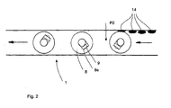
- FIG. 2 shows a partial view of a transport device 1 according to the invention.
- the impact body 14 arranged on one side section can push the vessels, ie the bottles, in the direction of the arrow P2 , In this way, the bottles 8 are moved and the head of the swing-top closure at least temporarily thrown away from the bottle. This brief throwing away is sufficient that the ceramic head can rest on the bottleneck when falling back. In this way it is achieved that the rubber seal essentially makes radially outward is positioned pointing and thus can be easily observed by the observation devices 3a and 3b.
- the impactors in this embodiment constitute the above-described alignment device 14.
- shock body 14 could also be provided below the conveyor belt or the bottles impact devices which push the bottle in their longitudinal direction. In this way, a short-term lifting of the head of the strap closure of the bottle and thus the alignment described above can be achieved.
- alignment devices could also be provided which act not on the bottle but on its closure. This could be, for example, arranged above the conveyor belt magnets, which also briefly lift the metal bracket and reach in this way an alignment of the head. It would also be possible to provide air nozzles which are distributed around the vessel at least at one and preferably at several points in the circumferential direction and in this way achieve a short lifting of the clip closure.
- the individual strap closures After the individual strap closures are aligned with the sealing rubber pointing radially outward, they can be recorded with the respective observation devices 3a and 3b. Based on the recorded images, it is possible to determine whether the respective bottle cap is still intact, ie in particular whether the rubber seal is dirty or damaged. It can also be determined whether the ceramic body of the clip closure is still intact. Bottles with unusable closures can be eliminated by a controllable Separierraum.
- the corresponding recorded image data of the closures can be output directly to the control to operating personnel, for example via a monitor.
Landscapes
- Physics & Mathematics (AREA)
- Health & Medical Sciences (AREA)
- Life Sciences & Earth Sciences (AREA)
- Chemical & Material Sciences (AREA)
- Analytical Chemistry (AREA)
- Biochemistry (AREA)
- General Health & Medical Sciences (AREA)
- General Physics & Mathematics (AREA)
- Immunology (AREA)
- Pathology (AREA)
- Investigating Materials By The Use Of Optical Means Adapted For Particular Applications (AREA)
- Analysing Materials By The Use Of Radiation (AREA)
Applications Claiming Priority (1)
| Application Number | Priority Date | Filing Date | Title |
|---|---|---|---|
| DE200510061087 DE102005061087A1 (de) | 2005-12-21 | 2005-12-21 | Vorrichtung und Verfahren zum Inspizieren von Gefäßverschlüssen |
Publications (2)
| Publication Number | Publication Date |
|---|---|
| EP1811288A2 true EP1811288A2 (fr) | 2007-07-25 |
| EP1811288A3 EP1811288A3 (fr) | 2010-03-03 |
Family
ID=37801454
Family Applications (1)
| Application Number | Title | Priority Date | Filing Date |
|---|---|---|---|
| EP06024678A Withdrawn EP1811288A3 (fr) | 2005-12-21 | 2006-11-29 | Dispositif et procédé destinés à l'inspection de fermetures de récipients |
Country Status (2)
| Country | Link |
|---|---|
| EP (1) | EP1811288A3 (fr) |
| DE (1) | DE102005061087A1 (fr) |
Cited By (3)
| Publication number | Priority date | Publication date | Assignee | Title |
|---|---|---|---|---|
| DE102009041212A1 (de) * | 2009-09-11 | 2011-04-07 | Krones Ag | Vorrichtung und Verfahren zum Kontrollieren von Gefäßverschlüssen |
| EP2784489A3 (fr) * | 2013-03-28 | 2015-03-18 | KS CONTROL Schneider/Ruhland GmbH | Dispositif d'inspection de joints de bouchons mécaniques de bouteilles à bouchons mécaniques |
| DE102018130940A1 (de) * | 2018-12-05 | 2020-06-10 | Krones Aktiengesellschaft | Vorrichtung und Verfahren zur Drehlageerkennung |
Families Citing this family (2)
| Publication number | Priority date | Publication date | Assignee | Title |
|---|---|---|---|---|
| DE102017201776B4 (de) | 2017-02-03 | 2023-03-09 | Krones Ag | Inspektionsvorrichtung und -verfahren zur Seitenwand- und Verschlusskopfinspektion von Behältern |
| IT202000012214A1 (it) * | 2020-05-25 | 2021-11-25 | Sacmi | Metodo e dispositivo per ispezionare un’incisione su un tappo di plastica |
Family Cites Families (3)
| Publication number | Priority date | Publication date | Assignee | Title |
|---|---|---|---|---|
| DE4115264C2 (de) * | 1991-05-10 | 1994-03-31 | Rudolf Zodrow | Inspektionsmaschine für Bügelverschlußflaschen |
| JP3307570B2 (ja) * | 1997-10-07 | 2002-07-24 | 株式会社キリンテクノシステム | 容器のキャップ検査装置 |
| DE10140009B4 (de) * | 2001-08-16 | 2004-04-15 | Krones Ag | Vorrichtung zur Inspektion gefüllter und verschlossener Flaschen |
-
2005
- 2005-12-21 DE DE200510061087 patent/DE102005061087A1/de not_active Ceased
-
2006
- 2006-11-29 EP EP06024678A patent/EP1811288A3/fr not_active Withdrawn
Cited By (3)
| Publication number | Priority date | Publication date | Assignee | Title |
|---|---|---|---|---|
| DE102009041212A1 (de) * | 2009-09-11 | 2011-04-07 | Krones Ag | Vorrichtung und Verfahren zum Kontrollieren von Gefäßverschlüssen |
| EP2784489A3 (fr) * | 2013-03-28 | 2015-03-18 | KS CONTROL Schneider/Ruhland GmbH | Dispositif d'inspection de joints de bouchons mécaniques de bouteilles à bouchons mécaniques |
| DE102018130940A1 (de) * | 2018-12-05 | 2020-06-10 | Krones Aktiengesellschaft | Vorrichtung und Verfahren zur Drehlageerkennung |
Also Published As
| Publication number | Publication date |
|---|---|
| EP1811288A3 (fr) | 2010-03-03 |
| DE102005061087A1 (de) | 2007-07-05 |
Similar Documents
| Publication | Publication Date | Title |
|---|---|---|
| EP2547591B1 (fr) | Tulipe de visibilité de couvercle | |
| EP0873510B1 (fr) | Dispositif d'inspection de bouteilles et autres articles similaires | |
| EP2290355B1 (fr) | Dispositif et procédé destinés à l'inspection de récipients étiquetés | |
| EP1553405B1 (fr) | Machine de contrôle | |
| EP2369328B1 (fr) | Procédé et dispositif pour examiner des impuretés dans des récipients rempli | |
| DE102006047150B4 (de) | Inspektionsvorrichtung für Behältnisse | |
| EP3204759B1 (fr) | Dispositif d'inspection et procédé d'inspection en lumière transmise de récipients | |
| EP2596340B1 (fr) | Système de détection pour l'orientation du joint de moule et des bossages de bouteilles et procédé pour le traitement de bouteilles. | |
| EP1346205B1 (fr) | Procede et dispositif d'inspection optique de bouteilles | |
| WO2008011960A1 (fr) | Dispositif d'inspection pour récipients | |
| EP3152550B1 (fr) | Dispositif d'inspection pour les fermetures de récipients | |
| EP1983333A2 (fr) | Dispositif d'inspection destiné à examiner des fermetures de récipients | |
| DE3114285C2 (de) | Prüfvorrichtung zur Feststellung von Mündungsfehlern von Glasgegenständen | |
| DE102007054657A1 (de) | Optische Erfassungseinrichtung, insbesondere zur Inspektion von Flaschen, sowie entsprechendes Visualisierungsverfahren | |
| EP3110701B1 (fr) | Dispositif d'inspection de recipients | |
| DE19920007C1 (de) | Vorrichtung zur Inspektion von Dichtflächen an Flaschen | |
| DE102004049260A1 (de) | Vorrichtung und Verfahren zur Erkennung von Behältern und/oder Gebinden | |
| DE102005023534B4 (de) | Vorrichtung zum Inspizieren etikettierter Gefäße | |
| EP1811288A2 (fr) | Dispositif et procédé destinés à l'inspection de fermetures de récipients | |
| WO2009115169A1 (fr) | Système de transport de bouteilles, et dispositif de traitement de bouteilles | |
| DE202012104043U1 (de) | Inspektionsvorrichtung für Behältnismündungen | |
| EP2860515A1 (fr) | Dispositif d'inspection, procédé d'inspection optique d'une surface d'un objet cylindrique et dispositif d'impression jet d'encre numérique | |
| DE3115636A1 (de) | Verfahren und vorrichtung zum pruefen der innenflaechen von runden behaeltern | |
| DE102005035868B4 (de) | Inspektionsvorrichtung und Inspektionsverfahren für Leergutkästen und die in diesen enthaltenen Behälter | |
| DE102004013774B4 (de) | Inspektionsvorrichtung für Behälter aus Glas oder einem transluzenten Material |
Legal Events
| Date | Code | Title | Description |
|---|---|---|---|
| PUAI | Public reference made under article 153(3) epc to a published international application that has entered the european phase |
Free format text: ORIGINAL CODE: 0009012 |
|
| AK | Designated contracting states |
Kind code of ref document: A2 Designated state(s): AT BE BG CH CY CZ DE DK EE ES FI FR GB GR HU IE IS IT LI LT LU LV MC NL PL PT RO SE SI SK TR |
|
| AX | Request for extension of the european patent |
Extension state: AL BA HR MK YU |
|
| RIC1 | Information provided on ipc code assigned before grant |
Ipc: B67B 3/26 20060101ALI20091026BHEP Ipc: G01N 21/90 20060101AFI20070312BHEP |
|
| PUAL | Search report despatched |
Free format text: ORIGINAL CODE: 0009013 |
|
| AK | Designated contracting states |
Kind code of ref document: A3 Designated state(s): AT BE BG CH CY CZ DE DK EE ES FI FR GB GR HU IE IS IT LI LT LU LV MC NL PL PT RO SE SI SK TR |
|
| AX | Request for extension of the european patent |
Extension state: AL BA HR MK RS |
|
| AKY | No designation fees paid | ||
| 17P | Request for examination filed |
Effective date: 20101019 |
|
| RBV | Designated contracting states (corrected) |
Designated state(s): AT BE BG |
|
| RBV | Designated contracting states (corrected) |
Designated state(s): DE FR IT |
|
| REG | Reference to a national code |
Ref country code: DE Ref legal event code: 8566 |
|
| 17Q | First examination report despatched |
Effective date: 20110705 |
|
| GRAP | Despatch of communication of intention to grant a patent |
Free format text: ORIGINAL CODE: EPIDOSNIGR1 |
|
| STAA | Information on the status of an ep patent application or granted ep patent |
Free format text: STATUS: THE APPLICATION IS DEEMED TO BE WITHDRAWN |
|
| 18D | Application deemed to be withdrawn |
Effective date: 20130411 |