EP0063820A2 - Nettoyeur utilisant des jets d'eau sous pression - Google Patents
Nettoyeur utilisant des jets d'eau sous pression Download PDFInfo
- Publication number
- EP0063820A2 EP0063820A2 EP82103587A EP82103587A EP0063820A2 EP 0063820 A2 EP0063820 A2 EP 0063820A2 EP 82103587 A EP82103587 A EP 82103587A EP 82103587 A EP82103587 A EP 82103587A EP 0063820 A2 EP0063820 A2 EP 0063820A2
- Authority
- EP
- European Patent Office
- Prior art keywords
- pressure jet
- water pressure
- cleaner according
- jet cleaner
- outlet pipes
- Prior art date
- Legal status (The legal status is an assumption and is not a legal conclusion. Google has not performed a legal analysis and makes no representation as to the accuracy of the status listed.)
- Granted
Links
Images


Classifications
-
- E—FIXED CONSTRUCTIONS
- E03—WATER SUPPLY; SEWERAGE
- E03C—DOMESTIC PLUMBING INSTALLATIONS FOR FRESH WATER OR WASTE WATER; SINKS
- E03C1/00—Domestic plumbing installations for fresh water or waste water; Sinks
- E03C1/12—Plumbing installations for waste water; Basins or fountains connected thereto; Sinks
- E03C1/30—Devices to facilitate removing of obstructions in waste-pipes or sinks
- E03C1/304—Devices to facilitate removing of obstructions in waste-pipes or sinks using fluid under pressure
- E03C1/306—Devices to facilitate removing of obstructions in waste-pipes or sinks using fluid under pressure by means of a tube connected to the water mains
Definitions
- the invention relates to a water pressure jet cleaner according to the preamble of claim 1.
- the object of the invention is to provide a water pressure jet cleaner which can be used to remove quickly blocked clogged drains in the simplest way with easy handling by using the pressure in the water pipe system?
- the object is achieved according to the features specified in the characterizing part of claim 1.
- Advantageous embodiments of the invention are specified in the subclaims.
- the cleaning head has one or more water outlet pipes, which can extend into the drain elbow or siphon, which can be inserted through the outlet strainer, for example in a wash basin.
- the water pressure is built up, on the other hand, this can also be used to generate a water flush deeper in the cast to release the blockage.
- the water outlet pipes are elastic, or at least partially elastic, so that they can be inserted or used in a wide variety of systems in that they can be easily pushed apart or pressed together.
- the water outlet pipes are arranged to be longitudinally displaceable in the cleaning head.
- the cleaning head comprises a holding block, preferably in the form of a solid block, in which the water outlet pipes are held.
- the water outlet pipes can be arranged in corresponding fitting bores in this solid block, so that they are thereby axially displaceable.
- the cleaning head is followed by a sealing plate through which the water outlet pipes pass.
- a sealing plate through which the water outlet pipes pass.
- the connecting piece is designed in the form of an elastic, watertight and sufficiently pressure-resistant hose. This ensures in a particularly advantageous manner that this connecting piece can be pulled onto a wide variety of taps without the need for special adaptation measures.
- the water pressure jet cleaner according to the invention can thus be used for a wide variety of taps.
- the connecting piece can also be applied directly with an outer skin or provided in the form of an additional hose.
- a clamping collar which can be locked by means of a screw is used as the clamping device.
- the clamping device consists of two axially movable parts, inside of which a pressing member is provided, whereby by axially moving the two clamping parts towards each other, this axial movement is converted into a transverse pressing movement on the connecting piece, and thus any can be firmly attached to a tap.
- This clamping device can be operated particularly easily and quickly and can also be used for different taps.
- a latching device is additionally provided so that after actuation of the clamping device, it is automatically held in the clamping position. It can also be easily released by unlocking it accordingly.
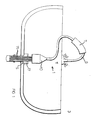
- a water pressure jet meter 1 is shown in use in a sink 3 with a spout 5, in which a blockage is to be solved.
- the water pressure jet cleaner 1 is connected with its connecting piece 7 to a water tap 9.
- a plurality of 6 water outlet pipes 15 protrude from the cleaning head 13, which are shown in the exemplary embodiment shown, and are correspondingly introduced into the spout 5. Since the water outlet pipes 15 are elastic or at least partially elastic, with which the radius can be changed by laterally displacing them, they can be passed through any pouring sieves, so that the drainage sieve can thereby be bridged.
- the partially elastic water outlet pipes are each bent outwards or slightly inwards, which means that they are adapted to a continuous sieve.
- the number, the length and the diameter of the water outlet pipes 15 can vary as required. A common diameter can be 6 mm, for example. With this arrangement, the water pressure can act unhindered without reduction in the pouring area.
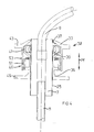
- FIGS. 2a and 3 in which the cleaning head 13 is shown in section.
- the cleaner head 13 consists essentially of a funnel-shaped housing 19, the upper influential end of which is firmly connected to the connecting hose 9.
- the training can be in one piece. But it is also possible that the connecting hose 9 is plugged on and is firmly connected, for example with clamps.
- Opposite is a holding block 21 with a plurality of fitting bores 23 through which the water inlet pipes 15 protrude.
- the design can be such that the water outlet pipes 15 can be pushed through these holes to vary the length of the water outlet pipes projecting outside.
- the water outlet pipes 15 are chamfered.
- the partially elastic water outlet pipes 15, for example in the form of plastic tubes, are arranged in a circle, the size of the holding block 21 being for example 36 mm in diameter and 25 mm in height.
- the outlet tube itself can between z. B. 4-20 cm and longer.
- sealing plate 17 is also provided, through which the water outlet pipes 15 also protrude.
- This sealing plate 17 is preferably made of an elastomeric material, for example sealing rubber, in order to thereby seal the back-flowing water from the drain 5.
- the sealing plate 17 can be considerably thicker than in the exemplary embodiment shown.
- an additional supporting plate - 18 may be provided, via which the sealing plate can be pressed 17 on the casting. 5
- the cleaning head 13 itself to be pressed onto the drain 5 together with the sealing plate 17 adjoining it.
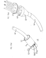
- FIGS. 2b and 4-6 in which u. a. the connecting piece 7 is shown.
- This essentially consists of a kind of insulating hose e.g. Insul foam rubber or foam rubber or the like, the consistency of which is essentially rubber foam-like and thus has good elasticity and strength. Therefore, this connector 7 can be drawn on a wide variety of taps without having to make a different adaptation of the connector to the respective tap.
- the connecting hose 9 can, for example, simply be plugged into the connecting piece 7 or can also be additionally fastened with hose clips (not shown in more detail).
- an outer skin 25 in the form of a rubber tube can also be provided.
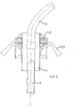
- connection piece 7 is fastened to the water tap 9 in the exemplary embodiment according to FIG. 2 b by means of a clamping device which is designed in the form of a clamping collar 27.
- a clamping device 32 which essentially consists of two clamping parts 33 and 35, which can be moved axially to one another in accordance with the arrow Pf.
- working surfaces 37 and 39 are provided which conically converge on the inside from the connecting piece 7, between which a pressing member in the form of a strip steel spiral 41 is arranged.
- the tapered, oblique work surfaces can, for example, be at an angle of approximately 100 to each other. Due to this deflection, the steel coil spring 4 1 is compressed due to its evenly moving spiral parts so that its inner diameter can be changed over a wide range.
- this clamping device 32 can also be used in a wide range of dimensions with a wide variety of taps.
- the two clamping parts 33 and 35 are simply pressed together by pressing together on corresponding handle sections 43 and 45.
- a latching device 49 which is acted upon by a spring 47, is also provided, a corresponding latching lug 51 engaging in recesses (not shown in more detail) and thus fixing the compressed clamping parts in their respective positions.
- the unlocking buttons 53 By simply pressing the unlocking buttons 53, the locking device 49 is released and the two clamping parts are pushed apart again.
- FIG. 5 shows a different embodiment of a clamping device, in which the axial movement of the two clamping parts relative to one another is effected via levers 55 which are provided separately.
- a latch means 49 is also in this example, as is not shown in detail here, is provided, for example, offset by 90 0 may be disposed to the respective levers 55th
- the application of the necessary clamping forces is ensured in that the two clamping parts 33 and 35 can be screwed into one another via a thread 57.
- an additional snap-in device 49 can be omitted.
Landscapes
- Engineering & Computer Science (AREA)
- Environmental & Geological Engineering (AREA)
- Health & Medical Sciences (AREA)
- Life Sciences & Earth Sciences (AREA)
- Hydrology & Water Resources (AREA)
- Public Health (AREA)
- Water Supply & Treatment (AREA)
- Cleaning By Liquid Or Steam (AREA)
- Sink And Installation For Waste Water (AREA)
- Quick-Acting Or Multi-Walled Pipe Joints (AREA)
Applications Claiming Priority (2)
| Application Number | Priority Date | Filing Date | Title |
|---|---|---|---|
| DE8112559U | 1981-04-28 | ||
| DE19818112559U DE8112559U1 (de) | 1981-04-28 | 1981-04-28 | Wasserdruckstrahlreiniger von verstopften abfluessen bei waschbecken, spuelbecken, badewannen, duschen, ausguessen usw. unter ausnuetzung des druckes im wasserleiungssystem durch direkte verbindung zwischen wasserausflusshahn und abflusssystem |
Publications (3)
| Publication Number | Publication Date |
|---|---|
| EP0063820A2 true EP0063820A2 (fr) | 1982-11-03 |
| EP0063820A3 EP0063820A3 (en) | 1983-02-02 |
| EP0063820B1 EP0063820B1 (fr) | 1986-08-13 |
Family
ID=6727169
Family Applications (1)
| Application Number | Title | Priority Date | Filing Date |
|---|---|---|---|
| EP82103587A Expired EP0063820B1 (fr) | 1981-04-28 | 1982-04-27 | Nettoyeur utilisant des jets d'eau sous pression |
Country Status (2)
| Country | Link |
|---|---|
| EP (1) | EP0063820B1 (fr) |
| DE (2) | DE8112559U1 (fr) |
Cited By (1)
| Publication number | Priority date | Publication date | Assignee | Title |
|---|---|---|---|---|
| GB2200709A (en) * | 1987-02-10 | 1988-08-10 | Alan Thompson | Device for clearing a waste trap |
Family Cites Families (10)
| Publication number | Priority date | Publication date | Assignee | Title |
|---|---|---|---|---|
| DE89519C (fr) * | ||||
| CH146338A (de) * | 1930-03-15 | 1931-04-15 | Sternegger Mathias | Schlauchbefestigungsbund. |
| DE806817C (de) * | 1949-01-18 | 1951-06-18 | Alexander Reineck | Gewindelose Rohrschnellkupplung |
| FR1092792A (fr) * | 1954-02-05 | 1955-04-27 | Raccord automatique | |
| GB792136A (en) * | 1955-10-12 | 1958-03-19 | George James Webbing Lambert | Improvements in joints and couplings for uniting two elements such as pipes |
| GB855797A (en) * | 1957-02-27 | 1960-12-07 | Reiss Engineering Company Ltd | Improvements in or relating to liquid spray arrangements |
| ZA721758B (en) * | 1972-03-14 | 1973-08-29 | R Onesta | A device to facilitate the clearing of a blocked drain |
| DE2444571A1 (de) * | 1974-09-18 | 1976-04-01 | Horst Bruns | Abflussreinigungsgeraet fuer sanitaere einrichtungen |
| DE2456678A1 (de) * | 1974-11-30 | 1976-08-12 | Oskar Biegel | Schlauchklemme zum anschliessen von druckschlaeuchen an zapfhaehne oder -ventile mit aussengewinde |
| US3937404A (en) * | 1975-06-09 | 1976-02-10 | Johnson Arthur L | Drain declogging device |
-
1981
- 1981-04-28 DE DE19818112559U patent/DE8112559U1/de not_active Expired
-
1982
- 1982-04-27 EP EP82103587A patent/EP0063820B1/fr not_active Expired
- 1982-04-27 DE DE8282103587T patent/DE3272531D1/de not_active Expired
Cited By (1)
| Publication number | Priority date | Publication date | Assignee | Title |
|---|---|---|---|---|
| GB2200709A (en) * | 1987-02-10 | 1988-08-10 | Alan Thompson | Device for clearing a waste trap |
Also Published As
| Publication number | Publication date |
|---|---|
| EP0063820A3 (en) | 1983-02-02 |
| DE3272531D1 (en) | 1986-09-18 |
| DE8112559U1 (de) | 1982-10-14 |
| EP0063820B1 (fr) | 1986-08-13 |
Similar Documents
| Publication | Publication Date | Title |
|---|---|---|
| DE2431516C3 (de) | Vorrichtung zur Abgabe von Fluiden | |
| DE3201505A1 (de) | Vorrichtung zum reinigen von rohren | |
| EP0467827B1 (fr) | Raccordement d'écoulement d'un élément sanitaire | |
| WO2008019804A1 (fr) | Dispositif de drainage | |
| DE1609101A1 (de) | Rohrverbindung | |
| EP0047482B1 (fr) | Egout ayant un orifice de nettoyage et un clapet anti-refoulement amovible | |
| DE29815815U1 (de) | Vorrichtung zur Vaginalspülung | |
| DE19912449C1 (de) | Regenwasserfilter | |
| EP0063820A2 (fr) | Nettoyeur utilisant des jets d'eau sous pression | |
| EP0643177B1 (fr) | Urinoir | |
| DE102014109806A1 (de) | Wasserauslaufarmatur für einen Waschtisch oder eine Spüle | |
| EP0804970A2 (fr) | Pistolet de pulvérisation à main pour appareil de nettoyage haute pression | |
| CH495524A (de) | Klosett mit Abgangsleitung | |
| DE19749779A1 (de) | Geruchsverschluß für ein Abflußrohr, insbesondere für das Abflußrohr eines Waschbeckens, einer Duschwanne oder dergleichen | |
| EP0188728A2 (fr) | Siphon encastré dans le mur | |
| EP0698695A1 (fr) | Sortie de cuvette de douche avec filtre | |
| DE102019001753A1 (de) | Ventilvorrichtung | |
| EP3647504A1 (fr) | Dispositif formant article sanitaire | |
| EP0250877A2 (fr) | Dispositif de débouchage d'un tuyau sanitaire | |
| DE102018200530A1 (de) | Fluidleitungseinsatz | |
| DE9205827U1 (de) | Befestigungsvorrichtung für das Ablaufrohr einer wandhängenden Toilette | |
| DE2454065B2 (de) | Anschlusseinrichtung eines elektrischen heisswasserbereiters | |
| DE2204905B1 (de) | Geruchverschluss fuer sanitaerkoerper, insbesondere fuer waschbecken | |
| DE202020101770U1 (de) | Abflussstopfenanordnung | |
| DE102006005166A1 (de) | Geruchsverschluß für Abwasserleitungen |
Legal Events
| Date | Code | Title | Description |
|---|---|---|---|
| PUAI | Public reference made under article 153(3) epc to a published international application that has entered the european phase |
Free format text: ORIGINAL CODE: 0009012 |
|
| AK | Designated contracting states |
Designated state(s): BE DE FR GB IT NL |
|
| PUAL | Search report despatched |
Free format text: ORIGINAL CODE: 0009013 |
|
| AK | Designated contracting states |
Designated state(s): BE DE FR GB IT NL |
|
| 17P | Request for examination filed |
Effective date: 19830126 |
|
| GRAA | (expected) grant |
Free format text: ORIGINAL CODE: 0009210 |
|
| AK | Designated contracting states |
Kind code of ref document: B1 Designated state(s): BE DE FR GB IT NL |
|
| REF | Corresponds to: |
Ref document number: 3272531 Country of ref document: DE Date of ref document: 19860918 |
|
| ET | Fr: translation filed | ||
| ITF | It: translation for a ep patent filed | ||
| PLBE | No opposition filed within time limit |
Free format text: ORIGINAL CODE: 0009261 |
|
| STAA | Information on the status of an ep patent application or granted ep patent |
Free format text: STATUS: NO OPPOSITION FILED WITHIN TIME LIMIT |
|
| 26N | No opposition filed | ||
| ITTA | It: last paid annual fee | ||
| PGFP | Annual fee paid to national office [announced via postgrant information from national office to epo] |
Ref country code: GB Payment date: 19940411 Year of fee payment: 13 |
|
| PGFP | Annual fee paid to national office [announced via postgrant information from national office to epo] |
Ref country code: FR Payment date: 19940418 Year of fee payment: 13 |
|
| PGFP | Annual fee paid to national office [announced via postgrant information from national office to epo] |
Ref country code: NL Payment date: 19940430 Year of fee payment: 13 |
|
| PGFP | Annual fee paid to national office [announced via postgrant information from national office to epo] |
Ref country code: BE Payment date: 19940506 Year of fee payment: 13 |
|
| PG25 | Lapsed in a contracting state [announced via postgrant information from national office to epo] |
Ref country code: GB Effective date: 19950427 |
|
| PG25 | Lapsed in a contracting state [announced via postgrant information from national office to epo] |
Ref country code: BE Effective date: 19950430 |
|
| BERE | Be: lapsed |
Owner name: WALTER KLAUS Effective date: 19950430 |
|
| PG25 | Lapsed in a contracting state [announced via postgrant information from national office to epo] |
Ref country code: NL Effective date: 19951101 |
|
| PG25 | Lapsed in a contracting state [announced via postgrant information from national office to epo] |
Ref country code: FR Effective date: 19951229 |
|
| NLV4 | Nl: lapsed or anulled due to non-payment of the annual fee |
Effective date: 19951101 |
|
| GBPC | Gb: european patent ceased through non-payment of renewal fee |
Effective date: 19950427 |
|
| REG | Reference to a national code |
Ref country code: FR Ref legal event code: ST |
|
| PGFP | Annual fee paid to national office [announced via postgrant information from national office to epo] |
Ref country code: DE Payment date: 19981217 Year of fee payment: 17 |
|
| PG25 | Lapsed in a contracting state [announced via postgrant information from national office to epo] |
Ref country code: DE Free format text: LAPSE BECAUSE OF NON-PAYMENT OF DUE FEES Effective date: 20000201 |