EP0063820B1 - Nettoyeur utilisant des jets d'eau sous pression - Google Patents
Nettoyeur utilisant des jets d'eau sous pression Download PDFInfo
- Publication number
- EP0063820B1 EP0063820B1 EP82103587A EP82103587A EP0063820B1 EP 0063820 B1 EP0063820 B1 EP 0063820B1 EP 82103587 A EP82103587 A EP 82103587A EP 82103587 A EP82103587 A EP 82103587A EP 0063820 B1 EP0063820 B1 EP 0063820B1
- Authority
- EP
- European Patent Office
- Prior art keywords
- water
- cleaning head
- outlet pipes
- jet pressure
- cleaner
- Prior art date
- Legal status (The legal status is an assumption and is not a legal conclusion. Google has not performed a legal analysis and makes no representation as to the accuracy of the status listed.)
- Expired
Links
- XLYOFNOQVPJJNP-UHFFFAOYSA-N water Substances O XLYOFNOQVPJJNP-UHFFFAOYSA-N 0.000 title claims description 47
- 238000004140 cleaning Methods 0.000 claims description 20
- 238000007789 sealing Methods 0.000 claims description 13
- 229920001971 elastomer Polymers 0.000 description 3
- 230000000694 effects Effects 0.000 description 2
- 229920001821 foam rubber Polymers 0.000 description 2
- 239000002245 particle Substances 0.000 description 2
- 230000006978 adaptation Effects 0.000 description 1
- 238000005266 casting Methods 0.000 description 1
- 238000001816 cooling Methods 0.000 description 1
- 238000006073 displacement reaction Methods 0.000 description 1
- 239000013536 elastomeric material Substances 0.000 description 1
- 239000004519 grease Substances 0.000 description 1
- 238000000034 method Methods 0.000 description 1
- 239000004033 plastic Substances 0.000 description 1
Images

Classifications
-
- E—FIXED CONSTRUCTIONS
- E03—WATER SUPPLY; SEWERAGE
- E03C—DOMESTIC PLUMBING INSTALLATIONS FOR FRESH WATER OR WASTE WATER; SINKS
- E03C1/00—Domestic plumbing installations for fresh water or waste water; Sinks
- E03C1/12—Plumbing installations for waste water; Basins or fountains connected thereto; Sinks
- E03C1/30—Devices to facilitate removing of obstructions in waste-pipes or sinks
- E03C1/304—Devices to facilitate removing of obstructions in waste-pipes or sinks using fluid under pressure
- E03C1/306—Devices to facilitate removing of obstructions in waste-pipes or sinks using fluid under pressure by means of a tube connected to the water mains
Definitions
- the invention relates to a water pressure jet cleaner according to the preamble of claim 1.
- Such a water pressure jet cleaner has become known, for example, from US Pat. No. 3,937,404, which comprises a hose which can be connected to a water tap and which can be introduced into a spout or siphon.
- this pressure jet cleaner comprises an elastic member through which the water hose is guided axially.
- a cleaner head with several outlet openings on the side, through which the pressurized water enters at an angle to the head
- This water pressure jet cleaner has several disadvantages. As can be seen from the aforementioned US-PS, the outer circumference of the cleaning head is only insignificantly smaller than the inlet opening of the spout. It is therefore not possible to use this cleaning head in almost all applications, since the spouts are usually provided with spout screens. These generally have, for example, an axis cross or several small circular and centrally arranged round outlet openings. In all these cases, where the spout has any kind of spout sieves, this previously known cleaning head cannot be used.
- a device for cleaning kitchen sinks has also become known from DE-C 89 519, a rigid tube with a lower outlet opening being used here.
- the use with pouring sieves is also not possible for the same reasons because of the large diameter of the water outlet pipe.
- vertical adjustment by the screw-in tube can only be achieved in small dimensions.
- the water pressure jet cleaner according to the invention can also be used for drains which contain a drain strainer.
- this generally applies to all drain screens that have become known since they comprise at least several circular openings.
- the cleaning head itself is arranged above the pouring sieve with the sealing piece and does not itself have to be inserted under the pouring sieve.
- the partial elasticity of the water outlet pipes is guaranteed.
- the water outlet pipes can be bent within certain limits and guided through the pouring sieve. Above all, no uncontrolled recoil movement is generated, since the partial elasticity still ensures that the outlet ends of the water outlet pipes are firmly inserted into the sump. Ultimately, the slanted outlet openings make it easier to insert the ends of the water outlet pipes into the sump in the siphon.
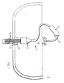
- a water pressure jet cleaner 1 is shown in use in a sink 3 with a spout 5, in which a blockage is to be solved.
- the water pressure jet cleaner 1 is connected with its connecting piece 7 to a tap 9.
- a plurality of 6 water outlet pipes 15 protrude from the cleaning head 13, which are shown in the exemplary embodiment shown, and are correspondingly introduced into the spout 5. Since the water outlet pipes 15 are elastic or at least partially elastic, which means that the radius can be changed by lateral displacement, these can be passed through any pouring sieves, so that the drain sieve can thereby be bridged.
- the partially elastic water outlet pipes are each bent outwards or slightly inwards, which means that they are adapted to a continuous sieve.
- the number, the length and the diameter of the water outlet pipes 15 can vary as required. A common diameter can be 6 mm, for example. With this arrangement, the water pressure can act unhindered without reduction in the pouring area.
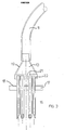
- FIGS. 2a and 3 in which the cleaning head 13 is shown in section.
- the cleaner head 13 consists essentially of a funnel-shaped housing 19, the upper influential end of which is firmly connected to the connecting hose 9.
- the training can be in one piece.
- the connecting hose 9 it is also possible for the connecting hose 9 to be plugged on and for example to be firmly connected with clamps.
- Opposite is a holding block 21 with a plurality of fitting bores 23 through which the water inlet pipes 15 protrude.
- the design can be such that the water outlet pipes 15 can be pushed through these bores in order to vary the length of the water outlet pipes which projects beyond the outside.
- the water outlet pipes 15 are chamfered.
- the partially elastic water outlet pipes 15, for example in the form of plastic tubes, are arranged in a circle, the size of the holding block 21 being for example 36 mm in diameter and 25 mm in height.
- the outlet tube itself can between z. B. 4-20 cm and longer.
- sealing plate 17 is also provided, through which the water outlet pipes 15 also protrude.
- This sealing plate 17 preferably consists of an elastomeric material, for example sealing rubber, in order to thereby seal the back-flowing water from the drain 5.
- the sealing plate 17 can be considerably thicker than in the exemplary embodiment shown.
- an additional base plate 18 can be provided between the cleaner head and the sealing plate, via which the sealing plate 17 can be pressed onto the casting 5. It is also possible, however, that the cleaning head 13 itself is pressed onto the drain 5 together with the sealing plate 17 adjoining it.
- FIGS. 2b and 4-6 in which u. a. the connecting piece 7 is shown.
- This essentially consists of a kind of insulating hose e.g. Insul foam rubber or foam rubber or the like, the consistency of which is essentially rubber foam-like and thus has good elasticity and strength. Therefore, this connecting piece 7 can be pulled onto a wide variety of taps without having to make a different adaptation of the connecting piece to the respective tap.
- the connecting hose 9 can be simply plugged into the connecting piece 7, for example, or can also be additionally fastened with hose clips, not shown in any more detail.
- an outer skin 25 in the form of a rubber tube can also be provided.
- connection piece 7 is fastened to the water tap 9 in the exemplary embodiment according to FIG. 2 b by means of a clamping device which is designed in the form of a clamping collar 27.
Landscapes
- Engineering & Computer Science (AREA)
- Environmental & Geological Engineering (AREA)
- Health & Medical Sciences (AREA)
- Life Sciences & Earth Sciences (AREA)
- Hydrology & Water Resources (AREA)
- Public Health (AREA)
- Water Supply & Treatment (AREA)
- Cleaning By Liquid Or Steam (AREA)
- Sink And Installation For Waste Water (AREA)
- Quick-Acting Or Multi-Walled Pipe Joints (AREA)
Claims (7)
Applications Claiming Priority (2)
| Application Number | Priority Date | Filing Date | Title |
|---|---|---|---|
| DE8112559U | 1981-04-28 | ||
| DE19818112559U DE8112559U1 (de) | 1981-04-28 | 1981-04-28 | Wasserdruckstrahlreiniger von verstopften abfluessen bei waschbecken, spuelbecken, badewannen, duschen, ausguessen usw. unter ausnuetzung des druckes im wasserleiungssystem durch direkte verbindung zwischen wasserausflusshahn und abflusssystem |
Publications (3)
| Publication Number | Publication Date |
|---|---|
| EP0063820A2 EP0063820A2 (fr) | 1982-11-03 |
| EP0063820A3 EP0063820A3 (en) | 1983-02-02 |
| EP0063820B1 true EP0063820B1 (fr) | 1986-08-13 |
Family
ID=6727169
Family Applications (1)
| Application Number | Title | Priority Date | Filing Date |
|---|---|---|---|
| EP82103587A Expired EP0063820B1 (fr) | 1981-04-28 | 1982-04-27 | Nettoyeur utilisant des jets d'eau sous pression |
Country Status (2)
| Country | Link |
|---|---|
| EP (1) | EP0063820B1 (fr) |
| DE (2) | DE8112559U1 (fr) |
Families Citing this family (1)
| Publication number | Priority date | Publication date | Assignee | Title |
|---|---|---|---|---|
| GB2200709A (en) * | 1987-02-10 | 1988-08-10 | Alan Thompson | Device for clearing a waste trap |
Citations (1)
| Publication number | Priority date | Publication date | Assignee | Title |
|---|---|---|---|---|
| GB855797A (en) * | 1957-02-27 | 1960-12-07 | Reiss Engineering Company Ltd | Improvements in or relating to liquid spray arrangements |
Family Cites Families (9)
| Publication number | Priority date | Publication date | Assignee | Title |
|---|---|---|---|---|
| DE89519C (fr) * | ||||
| CH146338A (de) * | 1930-03-15 | 1931-04-15 | Sternegger Mathias | Schlauchbefestigungsbund. |
| DE806817C (de) * | 1949-01-18 | 1951-06-18 | Alexander Reineck | Gewindelose Rohrschnellkupplung |
| FR1092792A (fr) * | 1954-02-05 | 1955-04-27 | Raccord automatique | |
| GB792136A (en) * | 1955-10-12 | 1958-03-19 | George James Webbing Lambert | Improvements in joints and couplings for uniting two elements such as pipes |
| ZA721758B (en) * | 1972-03-14 | 1973-08-29 | R Onesta | A device to facilitate the clearing of a blocked drain |
| DE2444571A1 (de) * | 1974-09-18 | 1976-04-01 | Horst Bruns | Abflussreinigungsgeraet fuer sanitaere einrichtungen |
| DE2456678A1 (de) * | 1974-11-30 | 1976-08-12 | Oskar Biegel | Schlauchklemme zum anschliessen von druckschlaeuchen an zapfhaehne oder -ventile mit aussengewinde |
| US3937404A (en) * | 1975-06-09 | 1976-02-10 | Johnson Arthur L | Drain declogging device |
-
1981
- 1981-04-28 DE DE19818112559U patent/DE8112559U1/de not_active Expired
-
1982
- 1982-04-27 EP EP82103587A patent/EP0063820B1/fr not_active Expired
- 1982-04-27 DE DE8282103587T patent/DE3272531D1/de not_active Expired
Patent Citations (1)
| Publication number | Priority date | Publication date | Assignee | Title |
|---|---|---|---|---|
| GB855797A (en) * | 1957-02-27 | 1960-12-07 | Reiss Engineering Company Ltd | Improvements in or relating to liquid spray arrangements |
Also Published As
| Publication number | Publication date |
|---|---|
| EP0063820A3 (en) | 1983-02-02 |
| DE3272531D1 (en) | 1986-09-18 |
| DE8112559U1 (de) | 1982-10-14 |
| EP0063820A2 (fr) | 1982-11-03 |
Similar Documents
| Publication | Publication Date | Title |
|---|---|---|
| DE2431516C3 (de) | Vorrichtung zur Abgabe von Fluiden | |
| EP0787864B1 (fr) | Dispositif de sécurité sanitaire | |
| DE3790241C3 (de) | Einhebel-Mischarmatur | |
| DE3007702A1 (de) | Inspektionskammer fuer eine drainageanlage | |
| DE9108260U1 (de) | Ablaufanschluß an einem Sanitärartikel | |
| EP0182327A1 (fr) | Dispositif pour limiter l'écoulement par étranglement dans la robinetterie d'eau | |
| DE29815815U1 (de) | Vorrichtung zur Vaginalspülung | |
| EP0063820B1 (fr) | Nettoyeur utilisant des jets d'eau sous pression | |
| DE2216678A1 (de) | Verbindungsstueck aus elastischem kunststoff | |
| DE69922947T2 (de) | Wassereinlauf für Badewanne in Form einer Kaskade | |
| EP0643177B1 (fr) | Urinoir | |
| DE6921769U (de) | Ausflussmundstueck fuer spritzerarme stroemungen | |
| CH495524A (de) | Klosett mit Abgangsleitung | |
| EP0916774A2 (fr) | Siphon pour un tuyau d'évacuation, en particulier pour un tuyau d'évacuation d'un lavabo, d'une douche ou équivalent | |
| EP1693316A1 (fr) | Dispositif de sortie avec un système de nettoyage | |
| EP3199715A2 (fr) | Trop-plein pour un bac, en particulier évier | |
| DE202020103189U1 (de) | Pistole zum Reinigen von Ohren | |
| DE102016120782B4 (de) | Hülsenverbindungsaufbau für Austrittsdüsen | |
| EP4283057B1 (fr) | Distributeur d'eau de rinçage | |
| EP3647504A1 (fr) | Dispositif formant article sanitaire | |
| DE102019001753A1 (de) | Ventilvorrichtung | |
| DE3606550C2 (fr) | ||
| DE29618346U1 (de) | Reinigungsgerät für Leitungen und Kanäle | |
| AT2673U1 (de) | Rohrförmiges element zur verbindung des ausflussrohres einer sanitäranlage mit einer abflussmündung oder einem wandstutzen | |
| EP0250877A2 (fr) | Dispositif de débouchage d'un tuyau sanitaire |
Legal Events
| Date | Code | Title | Description |
|---|---|---|---|
| PUAI | Public reference made under article 153(3) epc to a published international application that has entered the european phase |
Free format text: ORIGINAL CODE: 0009012 |
|
| AK | Designated contracting states |
Designated state(s): BE DE FR GB IT NL |
|
| PUAL | Search report despatched |
Free format text: ORIGINAL CODE: 0009013 |
|
| AK | Designated contracting states |
Designated state(s): BE DE FR GB IT NL |
|
| 17P | Request for examination filed |
Effective date: 19830126 |
|
| GRAA | (expected) grant |
Free format text: ORIGINAL CODE: 0009210 |
|
| AK | Designated contracting states |
Kind code of ref document: B1 Designated state(s): BE DE FR GB IT NL |
|
| REF | Corresponds to: |
Ref document number: 3272531 Country of ref document: DE Date of ref document: 19860918 |
|
| ET | Fr: translation filed | ||
| ITF | It: translation for a ep patent filed | ||
| PLBE | No opposition filed within time limit |
Free format text: ORIGINAL CODE: 0009261 |
|
| STAA | Information on the status of an ep patent application or granted ep patent |
Free format text: STATUS: NO OPPOSITION FILED WITHIN TIME LIMIT |
|
| 26N | No opposition filed | ||
| ITTA | It: last paid annual fee | ||
| PGFP | Annual fee paid to national office [announced via postgrant information from national office to epo] |
Ref country code: GB Payment date: 19940411 Year of fee payment: 13 |
|
| PGFP | Annual fee paid to national office [announced via postgrant information from national office to epo] |
Ref country code: FR Payment date: 19940418 Year of fee payment: 13 |
|
| PGFP | Annual fee paid to national office [announced via postgrant information from national office to epo] |
Ref country code: NL Payment date: 19940430 Year of fee payment: 13 |
|
| PGFP | Annual fee paid to national office [announced via postgrant information from national office to epo] |
Ref country code: BE Payment date: 19940506 Year of fee payment: 13 |
|
| PG25 | Lapsed in a contracting state [announced via postgrant information from national office to epo] |
Ref country code: GB Effective date: 19950427 |
|
| PG25 | Lapsed in a contracting state [announced via postgrant information from national office to epo] |
Ref country code: BE Effective date: 19950430 |
|
| BERE | Be: lapsed |
Owner name: WALTER KLAUS Effective date: 19950430 |
|
| PG25 | Lapsed in a contracting state [announced via postgrant information from national office to epo] |
Ref country code: NL Effective date: 19951101 |
|
| PG25 | Lapsed in a contracting state [announced via postgrant information from national office to epo] |
Ref country code: FR Effective date: 19951229 |
|
| NLV4 | Nl: lapsed or anulled due to non-payment of the annual fee |
Effective date: 19951101 |
|
| GBPC | Gb: european patent ceased through non-payment of renewal fee |
Effective date: 19950427 |
|
| REG | Reference to a national code |
Ref country code: FR Ref legal event code: ST |
|
| PGFP | Annual fee paid to national office [announced via postgrant information from national office to epo] |
Ref country code: DE Payment date: 19981217 Year of fee payment: 17 |
|
| PG25 | Lapsed in a contracting state [announced via postgrant information from national office to epo] |
Ref country code: DE Free format text: LAPSE BECAUSE OF NON-PAYMENT OF DUE FEES Effective date: 20000201 |