EP0063887B1 - Verfahren zum Herstellen von integrierten Schaltkreisen mit Josephson-Kontakten - Google Patents
Verfahren zum Herstellen von integrierten Schaltkreisen mit Josephson-Kontakten Download PDFInfo
- Publication number
- EP0063887B1 EP0063887B1 EP82301862A EP82301862A EP0063887B1 EP 0063887 B1 EP0063887 B1 EP 0063887B1 EP 82301862 A EP82301862 A EP 82301862A EP 82301862 A EP82301862 A EP 82301862A EP 0063887 B1 EP0063887 B1 EP 0063887B1
- Authority
- EP
- European Patent Office
- Prior art keywords
- layer
- josephson
- josephson junction
- junctions
- junction
- Prior art date
- Legal status (The legal status is an assumption and is not a legal conclusion. Google has not performed a legal analysis and makes no representation as to the accuracy of the status listed.)
- Expired
Links
Images


Classifications
-
- H—ELECTRICITY
- H10—SEMICONDUCTOR DEVICES; ELECTRIC SOLID-STATE DEVICES NOT OTHERWISE PROVIDED FOR
- H10N—ELECTRIC SOLID-STATE DEVICES NOT OTHERWISE PROVIDED FOR
- H10N60/00—Superconducting devices
- H10N60/01—Manufacture or treatment
- H10N60/0912—Manufacture or treatment of Josephson-effect devices
-
- H—ELECTRICITY
- H10—SEMICONDUCTOR DEVICES; ELECTRIC SOLID-STATE DEVICES NOT OTHERWISE PROVIDED FOR
- H10N—ELECTRIC SOLID-STATE DEVICES NOT OTHERWISE PROVIDED FOR
- H10N69/00—Integrated devices, or assemblies of multiple devices, comprising at least one superconducting element covered by group H10N60/00
-
- Y—GENERAL TAGGING OF NEW TECHNOLOGICAL DEVELOPMENTS; GENERAL TAGGING OF CROSS-SECTIONAL TECHNOLOGIES SPANNING OVER SEVERAL SECTIONS OF THE IPC; TECHNICAL SUBJECTS COVERED BY FORMER USPC CROSS-REFERENCE ART COLLECTIONS [XRACs] AND DIGESTS
- Y10—TECHNICAL SUBJECTS COVERED BY FORMER USPC
- Y10S—TECHNICAL SUBJECTS COVERED BY FORMER USPC CROSS-REFERENCE ART COLLECTIONS [XRACs] AND DIGESTS
- Y10S505/00—Superconductor technology: apparatus, material, process
- Y10S505/825—Apparatus per se, device per se, or process of making or operating same
- Y10S505/873—Active solid-state device
- Y10S505/874—Active solid-state device with josephson junction, e.g. squid
-
- Y—GENERAL TAGGING OF NEW TECHNOLOGICAL DEVELOPMENTS; GENERAL TAGGING OF CROSS-SECTIONAL TECHNOLOGIES SPANNING OVER SEVERAL SECTIONS OF THE IPC; TECHNICAL SUBJECTS COVERED BY FORMER USPC CROSS-REFERENCE ART COLLECTIONS [XRACs] AND DIGESTS
- Y10—TECHNICAL SUBJECTS COVERED BY FORMER USPC
- Y10S—TECHNICAL SUBJECTS COVERED BY FORMER USPC CROSS-REFERENCE ART COLLECTIONS [XRACs] AND DIGESTS
- Y10S505/00—Superconductor technology: apparatus, material, process
- Y10S505/825—Apparatus per se, device per se, or process of making or operating same
- Y10S505/917—Mechanically manufacturing superconductor
- Y10S505/922—Making josephson junction device
Definitions
- the invention relates to a method of manufacturing a Josephson junction integrated circuit device.
- a primary factor determining the efficacy of integrated circuit processes and the concomitant yield thereof is the number of steps comprising the process. For example, if a process consists of twelve steps and the expected yield of each of the steps is seventy-five percent, then the yield of operative devices at the completion of the twelve step process is 0.75 12 , or approximately three percent. Generally, this yield is considered unacceptably low. If, however, the process consists of eight steps, each with a yield probability of seventy-five percent, then the final yield for the eight step process is 0.75 8 , or ten percent. Thus by eliminating four steps, a three-fold improvement in yield is achieved without any improvement in the quality of the processing. Additionally, large numbers of processing steps engender problems with adhesion, step coverage and damage to prior deposited layers. The longer the fabrication sequence, the lower is the device throughput of the process.
- Table 1 on page 197 of Reference 1 enumerates the steps for a particular process utilised to fabricate interferometers combined with current injection logic gates.
- the process comprises depositing four super-conducting layers, viz., the ground plane, the lower Josephson electrode, the Josephson counter electrode and the control lines. Interconnections, interferometer loops and other circuit elements are formed from the last three layers.
- Each superconductive layer is separated from an adjacent superconductive layer by an insulator layer that is patterned to form vias which provide required electrical connections between layers.
- Josephson logic gates There are two basic types of Josephson logic gates, viz., current injection gates and magnetically controlled gates. All present day Josephson integrated circuits utilise one or both of these gate types. The fastest logic gates utilise a combination of the two as described in said Reference 2. All of these types of Josephson integrated circuits are subject to the disadvantages described above.
- the present invention reduces the number of manufacturing steps, and so improves yield, by depositing and patterning a single superconducting layer to provide both the ground plane for the device as a whole, and also one electrode for each individual Josephson junction of the device.
- the layer is patterned as necessary to isolate the electrodes of the junctions. Large-area junctions, which do not reach their critical currents, are used to form direct connections between the layers, and to enable cross-overs to be formed.
- FIG. 1 is a schematic wiring diagram of the JAWS integrated circuit of Figure 1.
- the various deposition and patterning steps of the process of Table 1 and illustrated in Figure 1 may utilise lift-off processing.
- lift-off processing an undercut photoresist mask is fabricated utilising any one of numerous well known techniques.
- the desired material is deposited through the mask and the mask with the overlying material is lifted off utilising a suitable solvent.
- the fabrication may utilise subtractive etching provided that an unetchable passivated surface is included beneath the layer being etched.
- the process of manufacturing the JAWS gate of Figure 1 in accordance with the prior art begins by depositing and patterning a layer S 1 to form the lower Josephson junction electrode and various interconnecting lines as required.
- the electrodes and lines denoted as S 1 are deposited on a suitable substrate.
- the various areas encompassed by the lines denoted as 5 1 comprise the deposited contact pads, junction electrodes and leads as illustrated.
- the second step in the prior art process is to deposit patches of insulation at various crossover points as required to insulate elements of the S 1 layer from a subsequently deposited S 2 layer. Such a patch of insulator is depicted as I 1 .
- the third step constitutes forming the Josephson tunnelling barriers, for example, by the oxidation of the associated surfaces of S 1 .
- S 1 comprises niobium
- an amorphous or polysilicon semiconductor may be deposited to form the barriers as indicated by the legend. Two such barrier formations are illustrated at B.
- the S 2 superconductive layer is then deposited forming the upper Josephson junction electrodes and other required interconnections. At the areas denoted as B, Josephson tunnelling junctions are formed by the S 1 -B-S 2 superposed layers.
- the fifth step of the prior art process comprises depositing or otherwise forming the resistors as the R 1 layer as indicated by the legends.
- the insulator layer 1 2 is deposited and via openings are formed in areas where contact to the layers S, or S 2 is required. For example, via openings 10, 11 and 12 in the 1 2 layer are utilised for contacting the S 1 layer. As will be appreciated from further steps to be described, the via openings 10 and 11 permit contact to the underlying S 1 pads by external contacts while the via opening 12 is utilised for contact to the underlying S 1 pad by the subsequently deposited groundplane.
- the final seventh step of the process is the deposition of the S 3 groundplane layer with contact vias 13 and 14 patterned out.
- the purpose of the groundplane is to reduce the inductance of the various lines formed in S 1 and S 2 , resulting in faster circuit operation.
- fully functional high performance chips require the layers I 2 and S 3 .
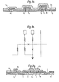
- Figure 2 shows the JAWS gate of Figure 1 A made in accordance with the present invention.
- This gate is representative of current injection logic circuits that may be implemented in accordance with the invention.
- the layers and steps utilised in such a fabrication process are summarised as follows:-
- the circuit of Figure 2 may be made using materials, patterning techniques and methods for Josephson barrier formation already in use in the art of Josephson circuit fabrication. These materials, for example, may be those in Table 1 above, the method of patterning being lift-off photoresist.
- Alternative materials such as niobium, hydrogenated silicon, silicon dioxide and molybdenum may be utilised for the superconductive elements, tunnelling barriers, insulators and resistors, respectively.
- S 1 may be anodised selectively either to replace I or to provide two insulator layers thus achieving flexibility with respect to fabricating capacitors and interconnects. It will be appreciated that the letter designations provided in the legend of Figure 2 refer to the layers listed in Table 2 above.
- the first step in the Josephson junction circuit fabrication process in accordance with the invention comprises deposition and patterning of the superconductive layer S,.
- the S, layer functions both as the Josephson junction lower electrode and as the groundplane for the circuit. Islands are formed in the S, layer to isolate junctions that are not directly connected to ground, and to isolate regions that will become crossovers.
- the S 1 layer is removed in areas where contact pads to the upper superconductor are to be located so as to prevent inadvertent shorting between the contact pads and the groundplane S 1 due to the mechanical pressures applied to the contact pads in making external connection thereto.
- the S 1 layer is removed within the rectangles 15 and 16 and islands 17 and 18 are formed in the S 1 layer. Island 17 is utilised to isolate the Josephson junctions forming the JAWS gate from the groundplane S, whereas the island 18 is formed to provide a crossover.
- the second step of the process according to the invention is the deposition and patterning of an insulator layer I.
- the I layer is patterned to form the Josephson openings for the JAWS gate and also to form large area openings for providing large area Josephson junctions for contact to the islands 17 and 18.
- Large area openings in the I layer are also required where contact to the groundplane S1 is desired.
- openings 19 and 20 in the I layer are utilised as the openings for the small area Josephson junctions of the JAWS gate.
- Vias 21 and 22 in the I layer provide the requisite openings for a crossover and the via 23 provides for contact to the groundplane portion of the layers S i .
- the third step in the process is the deposition of the resistors R on the I layer.
- resistors may be deposited exclusively on planar areas, thus avoiding step coverage problems sometimes prevalent in prior art circuits and processes. This provision is significant, since it is often necessary to make the resistors thin to obtain the required resistivity values.
- the Josephson barriers are now formed in the I layer vias 19-23, for example, by oxidising the underlying S, layer.
- the upper superconductive layer S z is deposited and patterned thus forming the Josephson junction upper electrodes, strip transmission line interconnects and contact pads.
- the barriers formed in the vias 19 and 20 provide the small area Josephson junctions that form the JAWS element itself.
- the barriers in the vias 21,22 and 23 provide large area Josephson junctions through which contact is made from the S z layer to the S 1 layer.
- the large area Josephson junctions must have sufficient critical current to remain at zero voltage at all required current loadings so as to effect the desired zero resistance contacts between the layers. Thus, it is appreciated that utilising this procedure increases circuit area requirements to provide the requisite critical current for this function. Since the inductance associated with a Josephson junction varies in inverse proportion to its critical current, the additional inductance of the large area junctions will be small compared to the inductance associated with the small junctions and will have negligible effect on the operating speed of the circuit.
- the circuit arrangement and process for forming a crossover in the S 2 layer is illustrated at 24.
- Leads 25 and 26 in the S 2 layer make contact to the island 18 in the 5 1 layer via the large area Josephson junctions formed by the vias 21 and 22, respectively, since the areas of these junctions in the vias 21 and 22 are such as to have sufficient critical current to remain at zero voltage for all current loadings of the circuit.
- a zero resistance path exists between the leads 25 and 26 through the island 18 which is insulated from the traversing lead of S 2 .
- This crossover configuration suffers from an area penalty and a small penalty in performance due to the increased inductance.
- the performance may be restored by fabricating matching capacitors to match the spurious inductance, thus involving an additional step in the fabrication. This additional step may or may not be required, depending on the refinement of the circuit design in which the crossover procedure is utilised.
- Figure 3 shows a JAWS gate integrated circuit fabricated according to the present invention and utilising the local anodisation technique of European patent application EP-A-0 046 648 (81303710.8).
- the schematic wiring diagram for the integrated circuit of Figure 3 is illustrated in Figure 3b.
- the steps and layers utilised in fabricating Josephson junction current injection logic integrated circuits such as that of Figure 3 in accordance with the present invention and utilising the local anodisation technique is summarised as follows:-
- the first three layers S 1 -B-S 2 are provided in accordance with the local anodisation technique, the steps associated therewith being concluded without intervening photolithography or other processing.
- materials other than molybdenum may also be suitable for fabricating the resistors.
- the letter designations set forth in the legend of Figure 3 refer to the layers delineated in Table 3.
- niobium for example, 300 nm thick
- the Josephson barrier may be formed either by oxidising the first layer of niobium or by depositing a barrier material.
- a second layer of niobium is then deposited over the barrier to a thickness, of for example, 20 to 60 nm.
- the resulting structure constitutes a Josephson junction covering the entire substrate area.
- the lower niobium layer is denoted as S 1
- the barrier as B
- the upper layer as 5 2 forming the trilayer structure S 1 -B-S 2 .
- the lower layer forms the Josephson lower electrodes and the upper layer forms the Josephson counter electrodes.
- the lower layer S 1 is also utilised as the ground plane for the structure.
- Individual small area junctions are then defined by forming a photoresist mask over those regions to be utilised as junctions and anodising the entire upper niobium layer to completion.
- the anodised area of the upper layer thus completely replaces the upper niobium material by insulation.
- Those regions covered by the photoresist mask are not anodised and thus retain the junctions located thereat.
- the junctions for the circuit are defined and the surrounding region covered by a layer of high quality, pinhole-free insulation all in one step.
- the steps and patterns utilised to incorporate the local anodisation technique of the said European patent application into the present process with respect to the fabrication of a JAWS circuit are delineated in Table 3 above and depicted in Figure 3.
- the trilayer S 1 -B-S 2 is deposited, masked and anodised in accordance with step 1.
- the Josephson junctions for the JAWS device as well as the large area junctions required for contact with the layer S 1 are formed.
- the trilayer S 1 -B-S z is patterned to form islands therein as required for the Josephson junctions of the JAWS gate as well as for effecting interconnections.
- the trilayer is removed under any bonding pads subsequently to be deposited with the S 3 layer.
- the trilayer is removed under the bonding pads to avoid shorting to the groundplane as discussed above with respect to Figure 2.
- the anodisation of the S 2 layer forms large area Josephson junctions 30, 31, 32 and 33 as well as the small area Josephson junctions 34 and 35 which form the elements of the JAWS gate.
- islands 36 and 37 are delineated in the trilayer S 1 -B-S z and the trilayer is removed within the rectangles 38 and 39.
- the large area Josephson junction 30 is utilised for effecting contact with the S 1 layer of the island 36, and the large area junctions 32 and 33 are utilised for effecting contact with the S 1 layer of the island 37.
- the large area Josephson junction 31 is utilised for making contact to the groundplane portion of the S 1 layer. It is appreciated that the island definition for the islands 36 and 37 are formed completely through the trilayer. It is further appreciated that the entire trilayer is removed from the rectangles 38 and 39.
- step 3 of the procedure the resistor material is deposited and patterned as indicated by the resistors R of Figure 3. Since the resistors are all formed on a planar surface, they can be relatively thin without encountering the step coverage problems sometimes prevalent with prior art procedures.
- step 4 of the process a layer I of insulation is deposited and via openings patterned therein as illustrated. The vias in the layer I are utilised for contacting the Josephson junctions formed in the trilayer S 1 -B-S z by the subsequently deposited layer S 3 and to contact the resistors R by the S 3 layer.
- the I layer also insulates the exposed edges of the islands 36 and 37 and insulates the resistor R.
- the I layer permits additional flexibility in control of circuit capacitance and inductance and in particular the stripline impedance of the S 3 layer is partially determined by the thickness of the layer I. Furthermore, by cutting holes in the layer I underneath S 3 , matching capacitors may be fabricated without additional steps.
- the circuit is completed by depositing and patterning the superconductive layer S 3 as illustrated.
- the S 3 layer provides contacts to all of the Josephson junctions, interconnecting strip transmission lines and crossovers.
- a crossover 40 is provided on the chip illustrated in Figure 3 and is effected in a manner similar to that described with respect to the crossover 24 of Figure 2.
- an additional means to fabricate crossovers is provided. Since the resistors R are sandwiched between the anodised layer S z and the insulator layer I, they may be utilised to provide crossover points. One such arrangement is indicated at 41. It is appreciated that the crossover utilising the resistor consumes less area than the crossover utilising the technique embodied by the crossover 40. Further circuit compactness may be achieved by situating resistors R underneath strip transmission lines S 3 . This arrangement would, however, degrade the transmission line characteristics of the strip transmission lines by adding dissipation.
- inventions of the invention are particularly applicable to current injection logic circuits.
- present invention is also applicable to magnetically controlled logic as well as the combination of magnetically controlled logic and current injection logic.
- Further embodiments of the invention with respect to magnetically controlled logic and the combination of magnetically controlled logic and current injection logic will be described hereinbelow with respect to, for example, a 1:2:1 interferometer and an asymmetric 2-junction injection gate, the 1:2:1 interferometer comprising a magnetically controlled gate.
- These two gates are typical of the two types of gates extant and additionally provide the highest performance gate combination in present day Josephson junction circuitry. It is appreciated that all other gates of the two basic types may be constructed by utilising readily apparent alterations of the techniques disclosed herein. Such gates include the JAWS gate described above, DCL gates and two-junction interferometers. Josephson microcircuits are typically constructed utilising one or both of two different superconductors such as niobium and lead alloys. The techniques of the present invention described herein are applicable to both materials, the basic concepts of the invention being applicable to more general circuits than the particular embodiments described. As discussed, the invention may also be utilised in conjunction with niobium junctions formed utilising the local anodisation technique of the said European patent application.
- the prior art two-junction asymmetric injection gate is illustrated in Figure 10A on page 135 of said Reference 2, depicting the structure of this gate fabricated utilising conventional lead alloy processing.
- the equivalent circuit for the gate is illustrated in Figure 1 OB on page 135 of said Reference 2.
- the embodiments of the present invention eliminate two deposition steps and two patterning steps compared with the prior art.
- the present invention combines the groundplane and one of the Joseph son electrodes into one layer and particularly, the Josephson lower electrode is incorporated with the groundplane.
- the present invention thus eliminates one layer of superconductor and the associated insulator layer.
- the sequence of various layers has been altered compared to the conventional processing described in said Reference 2.
- the 1:2:1 interferometers are constructed "upside down".
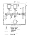
- FIG 4 a 1:2:1 interferometer fabricated in accordance with the present invention is illustrated.
- Figure 4a depicts a cross-section through the integrated circuit of Figure 4 as indicated by the line 4A.
- the layers and steps utilised in fabricating the Josephson junction integrated circuit of Figure 4 is summarised as follows:- Each of the layers and vias for Josephson junction definition are formed utilising processes known in the art. Each of the deposition steps except deposition of the barrier is followed by a patterning step, either lift-off or subtractive etching, depending upon the system and materials utilised.
- the letters of the legend of Figure 4 designating the layers correspond to those in Table 4.
- a superconductive layer S is deposited onto a substrate which typically comprises an oxidized silicon wafer.
- the layer S 1 forms the groundplane for the circuit and the lower Josephson junction electrodes for the junctions of the interferometer.
- S 1 corresponds to the counter electrode and the groundplane of Figure 6 on page 133 of said Reference 2.
- the superconductive layer S 1' if niobium, may or may not be anodised where the purpose of anodisation is to form a thin (approximately 35 nm) layer of high quality, pinhole free, insulation.
- the S 1 layer is also useful for forming matching capacitors, a circuit refinement useful in realising the fastest switching times and reliable performance.
- the second step is the deposition of an insulator layer 1 1 which is patterned to form openings defining the Josephson junctions as well as large areas openings defining large area Josephson junctions wherever electrical contacts to the groundplane are required.
- the 1 1 step may be effected utilising insulator deposition and subtractive etching or by forming a photoresist mask for lift-off followed by the insulator deposition and lift-off by dissolving the photoresist.
- deposition and subtractive etching may be effected by sputter depositing silicon dioxide following by etching with buffered hydrofluoric acid.
- the photoresist mask technique may be implemented by utilising evaporated silicon oxide.
- the anodisation must be removed in the 1 1 vias.
- the Nb 2 O 5 must be etched away in the I 1 vias or, alternatively, the anodisation blocked therein by a photoresist pattern.
- Vias 50, 51 and 52 are the Josephson junction openings in the 1 1 layer for the interferometer whereas the via 53 is utilised for effecting contact to the groundplane S 1 by means of a large area Josephson junction.
- the third step of the process comprises forming resistors R 1 including damping resistors, strip transmission line terminating resistors and feed resistors.
- the damping resistors surround the Josephson junction openings to form low inductance contacts to the Josephson junctions.
- the resistors may be fabricated by deposition through a lift-off photo mask typically utilising evaporated indium-gold alloy or by deposition followed by subtractive etching through a photo mask which, for example, may involve deposited molybdenum etched in a carbon tetrafluoride 8% oxygen plasma.
- the fourth step of the process is the formation of the Josephson tunnelling barriers.
- the barrers may comprise native oxide or may be deposited barriers such as amorphous hydrogenated silicon.
- the barriers are denoted as B and are defined by the openings 50, 51, 52 and 53 in the insulator layer I 1 .
- the barrier formation is followed by the deposition of a superconductive layer S z forming the Josephson junction upper electrodes.
- the formation of the S 2 layer may be effected by any of a variety of known techniques such as those discussed above.
- the S 2 layer is patterned to form the inductive loops of the interferometer as well as any required strip transmission line interconnections.
- the S 2 layer thus forms inductances L m and L k on Figure 7b on page 134 of said Reference 2.
- the S z layer also forms the large area Josephson junction contacts to the groundplane layer S 1 such as that effected through the via 53.
- the method of contacting the groundplane through a large area Josephson junction adds insignificant inductance to the groundplane contact.
- the amount of inductance added to the circuit by the large area Josephson junction is typically smaller than the stray inductance prevalent in conventional Josephson interferometers and should not present a serious problem for circuit operation.
- the technique of utilising the large area Josephson junction contact results in the disadvantage that the contacts to the groundplane are approximately ten times larger in area than the Josephson junctions of the interferometer in order to achieve the desired critical current margins. This is, however, a small area requirement relative to the size of the entire interferometer.
- the fifth step in the process is the deposition of an insulator layer 1, with via openings where required. Such vias may be utilised for control line to strip transmission line contacts and control line to terminating resistor contacts. Two such vias are designated by reference numerals 54 and 55.
- the seventh step in the process comprises deposition and patterning of a superconductive layer S 3 comprising the superconducting control lines for the circuit. The control lines S 3 contact the circuit through the vias 54 and 55. For simplicity only one control line is illustrated whereas actual circuits require two or more control lines. The multiple control lines may be deposited and patterned simultaneously.
- Such techniques include the use of additional insulator layers to increase inductance or forming holes in the groundplane for increasing inductance.
- Capacitors may be formed under the strip transmission lines to provide an impedance match in regions of unavoidable increased inductance.
- contact pads are not illustrated in Figure 4, the S 1 layer should be removed beneath any contact pads for the reasons discussed above with respect to Figures 2 and 3.
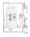
- Figure 5 illustrates a two junction asymmetric current injection gate which may be fabricated utilising identically the sequence of steps and methods of deposition and patterning as discussed above with respect to Figure 4. The details of the process discussed above with respect to Figure 4 and Table 4 are applicable to Figure 5.
- Figure 5a illustrates a cross-section taken through the line 5A of Figure 5. The letter designations of the legend of Figure 5 correspond to those in Table 4.
- Step 1 comprises depositing and patterning the S 1 layer.
- the S 1 layer does not require patterning. This layer, however, should be removed underneath external contact pads for the reasons discussed above.
- the removal of the S 1 layer beneath a contact pad is indicated by reference numeral 60. In practical circuits holes may be formed in the S 1 layer to increase inductance values or to form on-chip transformers as part of the power supply arrangement.
- the next step constitutes deposition of the 1 1 insulator layer and patterning the 1 1 layer to form vias 61, 62 and 63.
- the two small opening vias 61 and 62 define the Josephson junctions of the gate and the large opening via 63 provides a contact to the Josephson base electrode and groundplane S 1 via a large area Josephson junction.
- the next step comprises depositing and patterning resistor material to form a damping resistor 64 and a terminating resistor 65. In a manner similar to that discussed with respect to Figure 4, the damping resistor 64 forms a "ring" around the Josephson openings.
- the Josephson barriers are formed in the vias 61, 62 and 63 followed by the step of depositing and patterning the Josephson counterelectrode superconductive layer S Z .
- the S z layer not only forms the Josephson counterelectrode for the asymmetric gate, but a requisite inductive loop and connecting strip transmission line.
- the injection gate is essentially complete.
- Another insulator layer and superconductive layer are, however, necessary to complete the interferometer portion of the circuit illustrated and discussed above with respect to Figure 4. These layers may be deposited over the injection gate of Figure 5 where the superconductive layer will provide a flux shield for the gate.
- the last two steps of the process comprises depositing and patterning the insulator layer I 2 and depositing and patterning the superconductive layer S 3 . It is appreciated that the insulator layer I z is unpatterned except over contact pads. An island is formed on the S 3 layer to provide external contact to the S 2 layer of the gate. This contact pad is designated by reference numeral 66.
- the circuit of Figure 5 conforms to the equivalent circuit of Figure 1 OA on page 135 of Reference 2.
- the parasitic parameter values of the circuit of Figure 5 will be different from those of circuits conventionally fabricated.
- the inductance of any line passing over a region where no groundplane exists will be increased slightly.
- This increase in stray inductance may decrease margins and performance slightly compared to prior art circuits, but the loss in these factors may be regained because of the simpler fabrication provided by the present invention.
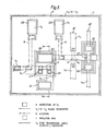
- FIG. 6 an integrated circuit chip is illustrated containing the 1:2:1 interferometer and the asymmetric two junction injection gate fabricated in accordance with the invention and utilising the local anodisation technique of European patent application number 81303710.8 to define the junction areas.
- the layers and steps utilised in fabricating the circuit of Figure 6 are summarised as follows:- S 1 -B-S z are deposited sequentially with no intervening patterning steps.
- the processing for the integrated circuit of Figure 6 is initiated by constructing the S 1 -B-S z trilayer in accordance with the said European patent application EP-A-0 046 648 (81303710.8). Firstly a film of niobium approximately 300 nm thick is deposited followed by the Josephson barrier formation.
- the barrier layer typically plasma or thermal oxidation or deposition of a semiconductor material is utilised to form the barrier layer.
- the upper layer of the trilayer structure is formed by deposition of a thin layer of niobium approximately 20 to 60 nm thick.
- the substrate is covered by essentially one continuous Josephson junction.
- the three layers may be completed in situ without removing the substrate from the vacuum chamber.
- the fabrication of the trilayer proceeds without any intervening processing or patterning steps.
- the Josephson junctions are thus formed on a clean, unpatterned, undamaged, and uncontaminated surface. This procedure provides Josephson junctions with superior properties to junctions formed with more conventional procedures.
- barriers are deposited utilising chemical vapour deposition, it is crucial to deposit the barrier on an unpatterned surface.
- the first step after formation of the trilayer comprises forming a pattern in photoresist over the desired junction areas and then anodising completely through the S 2 layer.
- a layer of high quality insulator is formed over the S 1 layer. This layer will form the groundplane for the circuit of Figure 6 as well as the lower Josephson electrodes.
- photoresist is formed within rectangles 70, 71, 72, 73, 74 and 75. After anodisation the areas within the rectangles 70-75 have trilayer junction structures and over the remainder of the substrate, the S 2 niobium layer has been completely anodised to niobium oxide.
- the multilayer S 1 -B-S 2 -A is patterned to remove those areas over which contact pads are to be formed. For example, the multilayer is removed within the rectangle 76. The reason for removing the multilayer under the contact pad has been discussed above with respect to Figures 2 and 3.
- the next step comprises depositing and patterning the resistor material, which typically may be molybdenum, approximately 800 Angstrom units thick. The resistors R are deposited only over planar regions, thus obviating the step coverage problem sometimes prevalent in conventional processes.
- the next step in the process comprises depositing the 1 1 insulator layer patterned to form vias to the Josephson junctions and to the resistors R. Typically the 1, layer comprises silicon dioxide approximately 250 nm thick.
- the 1 1 layer also insulates the patterned edges of S 1 -B-S 2- A and provides additional low dielectric constant groundplane insulation for the superconducting strip transmission lines to be subsequently formed in the S 3 layer.
- the S 3 superconductive layer is deposited and patterned to form strip transmission lines, inductive loops and groundplane contacts through previously formed large area Josephson junctions.
- the S 3 layer is preferable composed of niobium approximately 300 nm thick.
- the S 3 layer thus completes the two junction asymmetric injection gate by coupling the Josephson junction areas 70 and 71 and providing an external contact pad at 76.
- the S 3 layer also completes the three junction interferometer by intercoupling the junctions formed in the rectangles 73, 74 and 75 connecting the appropriate points to the groundplane via the large area Josephson junction within the rectangle 72.
- an insulator layer I z is deposited and vias are patterned for contacts to the S 4 layer to be subsequently deposited.
- a via is also patterned in the I 2 layer for contact to the pad at 76.
- the I 2 layer preferably comprises silicon dioxide approximately 350 nm thick.
- the S 4 superconductive layer is next deposited and patterned to form the control lines over the interferometer and the flux shield over the injection gate.
- Matching capacitors may be fabricated by utilising appropriate cutouts in the 1 1 layer underneath the strip transmission lines and additional inductance may be obtained in superconducting loops by adding insulator thickness or groundplane cutouts. It will be noted that the circuits formed in Figure 6 are precisely the required circuits and can be designed with desired parameter values. Although some of the various stray capacitances and inductances will be different with respect to a comparable circuit fabricated using a conventional process, these differences can be accommodated by utilising the circuit refinements discussed above.
- the present processes eliminate a significant number of steps compared to the prior art processes. This results in significantly greater yields of acceptable circuits and considerably shortens the time required for manufacture.
- the resultant circuits are identical in all essential ways to conventionally fabricated circuits. All significant circuit parameters are virtually identical to those of circuits fabricated utilising conventional processes. All significant types of Josephson logic circuits may be implemented utilising the processes herein disclosed. Josephson circuits comprising all refractory materials may be fabricated utilising the processes of the present invention.
- Josephson circuits comprising all refractory materials may be fabricated utilising the processes of the present invention.
- the invention provides the advantage of forming resistors on planar surfaces.
- relatively thin resistors may be utilised without problems with step coverage and without creating subsequent step coverage problems.
- a particular embodiment of the present invention utilises large area Josephson junctions to form superconducting contacts.
- superconducting shorts could be formed with the disadvantage of an additional patterning step to remove the barrier in these areas.
- the present invention when the present invention is utilised in conjunction with local anodisation to form the Josephson junctions, the following advantages are obtained.
- the tunnelling barriers are formed on a fresh unprocessed surface.
- the junction characteristics are dependent upon the quality of the superconductor at the barrier-superconductor interface to a depth of the superconducting coherence length, which in niobium is typically approximately 8 nm.
- the present process that permits junction fabrication on an unprocessed surface is generally advantageous with respect to prior art processes that do not provide this feature.
- the junction parameters can be obtained. Based upon these parameters the logic fabrication can be aborted, continued, or modified, thus, increasing yield and/or productivity. For example, based upon the junction critical current obtained on the test wafer, the logic chip can be processed utilising a different size Josephson junction, thus obtaining the correct design value for the critical current, or the resistance values can be modified to ensure proper circuit operation.
- the resistors are fabricated directly on top of the anodised niobium but underneath the first layer of deposited insulator, whereas in conventional processing the resistors are deposited on top of both of these layers. This configuration leads to lower inductances associated with the resistors which is advantageous for circuit performance.
- the present arrangement also permits the use of resistors as crossovers. Furthermore, resistors and strip transmission lines can be fabricated on the same substrate area permitting very efficient utilisation of available area if the degradation of the strip transmission line characteristics can be tolerated.
- the first layer of deposited insulator provides several functions.
- the layer forms vias to the Josephson junctions, the resistors and to the groundplane contacts.
- the layer provides an etch stop for the upper niobium etch step.
- the layer provides additional groundplane insulation of desirably low dielectric constant and functions as the insulator for the edges patterned on the first superconductor layer.
- Capacitors can be formed with no additional fabrication steps, by holes in the deposited insulator down to the anodised niobium. These capacitors can be utilised at crossovers to match the strip transmission line impedance.
Landscapes
- Engineering & Computer Science (AREA)
- Manufacturing & Machinery (AREA)
- Superconductor Devices And Manufacturing Methods Thereof (AREA)
Claims (4)
Applications Claiming Priority (2)
| Application Number | Priority Date | Filing Date | Title |
|---|---|---|---|
| US06/252,528 US4430662A (en) | 1981-04-09 | 1981-04-09 | Superconductive tunnel junction integrated circuit |
| US252528 | 1981-04-09 |
Publications (2)
| Publication Number | Publication Date |
|---|---|
| EP0063887A1 EP0063887A1 (de) | 1982-11-03 |
| EP0063887B1 true EP0063887B1 (de) | 1985-03-06 |
Family
ID=22956390
Family Applications (1)
| Application Number | Title | Priority Date | Filing Date |
|---|---|---|---|
| EP82301862A Expired EP0063887B1 (de) | 1981-04-09 | 1982-04-08 | Verfahren zum Herstellen von integrierten Schaltkreisen mit Josephson-Kontakten |
Country Status (4)
| Country | Link |
|---|---|
| US (2) | US4430662A (de) |
| EP (1) | EP0063887B1 (de) |
| JP (1) | JPS57177581A (de) |
| DE (1) | DE3262485D1 (de) |
Families Citing this family (36)
| Publication number | Priority date | Publication date | Assignee | Title |
|---|---|---|---|---|
| JPS5979584A (ja) * | 1982-10-29 | 1984-05-08 | Hitachi Ltd | ジヨセフソン集積回路用抵抗 |
| JPS59172281A (ja) * | 1983-03-18 | 1984-09-28 | Agency Of Ind Science & Technol | ジヨセフソンlsi |
| US4554567A (en) * | 1983-03-21 | 1985-11-19 | Sperry Corporation | Superconductive integrated circuit incorporating a magnetically controlled interferometer |
| US4544937A (en) * | 1983-04-01 | 1985-10-01 | Sperry Corporation | Formation of normal resistors by degenerate doping of substrates |
| US4589961A (en) * | 1984-08-31 | 1986-05-20 | Sperry Corporation | Aluminum mask anodization with lift-off for patterning Josephson junction devices |
| US5795849A (en) * | 1987-12-21 | 1998-08-18 | Hickman; Paul L. | Bulk ceramic superconductor structures |
| US4878094A (en) * | 1988-03-30 | 1989-10-31 | Minko Balkanski | Self-powered electronic component and manufacturing method therefor |
| US5084404A (en) * | 1988-03-31 | 1992-01-28 | Advanced Micro Devices | Gate array structure and process to allow optioning at second metal mask only |
| US4904980A (en) * | 1988-08-19 | 1990-02-27 | Westinghouse Electric Corp. | Refractory resistors with etch stop for superconductor integrated circuits |
| US4904341A (en) * | 1988-08-22 | 1990-02-27 | Westinghouse Electric Corp. | Selective silicon dioxide etchant for superconductor integrated circuits |
| JPH0379093A (ja) * | 1989-08-23 | 1991-04-04 | Hitachi Ltd | ジョセフソン集積回路 |
| JP2964112B2 (ja) * | 1992-08-11 | 1999-10-18 | セイコーインスツルメンツ株式会社 | 直流駆動型超伝導量子干渉素子 |
| US5358928A (en) * | 1992-09-22 | 1994-10-25 | Sandia Corporation | High temperature superconductor step-edge Josephson junctions using Ti-Ca-Ba-Cu-O |
| DE4320484A1 (de) * | 1993-06-21 | 1994-12-22 | Dornier Gmbh | Steuerbares Supraleiter-Bauelement |
| US5863868A (en) * | 1996-04-08 | 1999-01-26 | Trw Inc. | Superconductive quantum interference device for digital logic circuits |
| US5962865A (en) * | 1997-04-11 | 1999-10-05 | Trw Inc. | Low inductance superconductive integrated circuit and method of fabricating the same |
| US6404615B1 (en) | 2000-02-16 | 2002-06-11 | Intarsia Corporation | Thin film capacitors |
| US6486530B1 (en) | 2000-10-16 | 2002-11-26 | Intarsia Corporation | Integration of anodized metal capacitors and high temperature deposition capacitors |
| US6518673B2 (en) * | 2001-06-15 | 2003-02-11 | Trw Inc. | Capacitor for signal propagation across ground plane boundaries in superconductor integrated circuits |
| JP3820444B2 (ja) * | 2002-01-25 | 2006-09-13 | 独立行政法人情報通信研究機構 | トンネル接合素子を用いた同調回路および超伝導集積回路 |
| US20050092981A1 (en) * | 2003-11-04 | 2005-05-05 | Hunt Jeffrey H. | Superconducting integrated circuit and methods of forming same |
| US20070284097A1 (en) * | 2006-06-08 | 2007-12-13 | Halliburton Energy Services, Inc. | Consumable downhole tools |
| US20080257549A1 (en) * | 2006-06-08 | 2008-10-23 | Halliburton Energy Services, Inc. | Consumable Downhole Tools |
| US7591318B2 (en) * | 2006-07-20 | 2009-09-22 | Halliburton Energy Services, Inc. | Method for removing a sealing plug from a well |
| US7615385B2 (en) | 2006-09-20 | 2009-11-10 | Hypres, Inc | Double-masking technique for increasing fabrication yield in superconducting electronics |
| US20080202764A1 (en) | 2007-02-22 | 2008-08-28 | Halliburton Energy Services, Inc. | Consumable downhole tools |
| US8395053B2 (en) * | 2007-06-27 | 2013-03-12 | Stats Chippac Ltd. | Circuit system with circuit element and reference plane |
| US8235102B1 (en) | 2008-03-26 | 2012-08-07 | Robertson Intellectual Properties, LLC | Consumable downhole tool |
| US8327926B2 (en) | 2008-03-26 | 2012-12-11 | Robertson Intellectual Properties, LLC | Method for removing a consumable downhole tool |
| US9520180B1 (en) | 2014-03-11 | 2016-12-13 | Hypres, Inc. | System and method for cryogenic hybrid technology computing and memory |
| US20170047276A1 (en) * | 2015-08-13 | 2017-02-16 | Advanced Semiconductor Engineering, Inc. | Semiconductor device package and method of manufacturing the same |
| CN105702849B (zh) * | 2016-02-01 | 2018-09-07 | 中国科学院上海微系统与信息技术研究所 | 台阶区域覆盖有超导覆盖层的超导电路结构及其制备方法 |
| US10367134B2 (en) | 2017-06-07 | 2019-07-30 | International Business Machines Corporation | Shadow mask sidewall tunnel junction for quantum computing |
| US10665769B2 (en) * | 2018-06-19 | 2020-05-26 | Intel Corporation | Quantum circuit assemblies with vertically-stacked parallel-plate capacitors |
| US10916690B2 (en) * | 2018-11-28 | 2021-02-09 | International Business Machines Corporation | Electrical leads for trenched qubits |
| US12108689B2 (en) | 2021-03-12 | 2024-10-01 | International Business Machines Corporation | Trimmable inductors for qubit frequency tuning |
Family Cites Families (12)
| Publication number | Priority date | Publication date | Assignee | Title |
|---|---|---|---|---|
| US3849276A (en) * | 1971-03-19 | 1974-11-19 | Ibm | Process for forming reactive layers whose thickness is independent of time |
| US4176290A (en) * | 1976-10-27 | 1979-11-27 | Nippon Telegraph And Telephone Public Corporation | Superconductive Josephson circuit device |
| US4117503A (en) | 1977-06-30 | 1978-09-26 | International Business Machines Corporation | Josephson interferometer structure which suppresses resonances |
| JPS5423239A (en) * | 1977-07-21 | 1979-02-21 | Nippon Denso Co Ltd | Rotary refrigerator |
| US4176365A (en) * | 1978-05-08 | 1979-11-27 | Sperry Rand Corporation | Josephson tunnel junction device with hydrogenated amorphous silicon, germanium or silicon-germanium alloy tunneling barrier |
| US4224630A (en) * | 1978-08-25 | 1980-09-23 | Sperry Corporation | Multiple weak-link SQUID |
| US4220959A (en) | 1979-03-23 | 1980-09-02 | Sperry Corporation | Josephson tunnel junction with polycrystalline silicon, germanium or silicon-germanium alloy tunneling barrier |
| DE3161996D1 (en) * | 1980-02-20 | 1984-03-01 | Fujitsu Ltd | Superconductive logic device incorporating a josephson junction |
| US4421785A (en) * | 1980-08-18 | 1983-12-20 | Sperry Corporation | Superconductive tunnel junction device and method of manufacture |
| US4344052A (en) * | 1980-09-29 | 1982-08-10 | International Business Machines Corporation | Distributed array of Josephson devices with coherence |
| US4315255A (en) | 1980-10-27 | 1982-02-09 | The United States Of America As Represented By The Secretary Of The Navy | Multiple-quantum interference superconducting analog-to-digital converter |
| US4344223A (en) * | 1980-11-26 | 1982-08-17 | Western Electric Company, Inc. | Monolithic hybrid integrated circuits |
-
1981
- 1981-04-09 US US06/252,528 patent/US4430662A/en not_active Expired - Fee Related
-
1982
- 1982-04-08 DE DE8282301862T patent/DE3262485D1/de not_active Expired
- 1982-04-08 EP EP82301862A patent/EP0063887B1/de not_active Expired
- 1982-04-09 JP JP57058353A patent/JPS57177581A/ja active Pending
-
1983
- 1983-11-14 US US06/550,847 patent/US4498228A/en not_active Expired - Fee Related
Also Published As
| Publication number | Publication date |
|---|---|
| DE3262485D1 (en) | 1985-04-11 |
| US4498228A (en) | 1985-02-12 |
| US4430662A (en) | 1984-02-07 |
| EP0063887A1 (de) | 1982-11-03 |
| JPS57177581A (en) | 1982-11-01 |
Similar Documents
| Publication | Publication Date | Title |
|---|---|---|
| EP0063887B1 (de) | Verfahren zum Herstellen von integrierten Schaltkreisen mit Josephson-Kontakten | |
| US4554567A (en) | Superconductive integrated circuit incorporating a magnetically controlled interferometer | |
| US6188084B1 (en) | Low inductance superconductive integrated circuit and method of fabricating the same | |
| EP0484253B1 (de) | Supraleitende Einrichtung mit extrem dünnen supraleitenden Kanal aus oxydischem supraleitendem Material und Methode zu deren Herstellung | |
| US5326988A (en) | Superconducting switching device and method of manufacturing same | |
| US5071832A (en) | Field effect type josephson transistor | |
| US5621223A (en) | Superconducting device having a reduced thickness of oxide superconducting layer and method for manufacturing the same | |
| JPH05102547A (ja) | ジヨセフソン集積回路装置の製造方法 | |
| JPS6257263A (ja) | ジヨセフソン集積回路の製造方法 | |
| US4178602A (en) | Thin film cryotron | |
| Nakagawa et al. | Fabrication process for Josephson computer ETL-JC1 using Nb tunnel junctions | |
| JP2727773B2 (ja) | ジョセフソン集積回路の製造方法 | |
| JP2989943B2 (ja) | 超電導集積回路の製造方法 | |
| JPS58125880A (ja) | ジヨセフソン接合素子 | |
| JPH06302870A (ja) | 薄膜素子およびその製造方法 | |
| JPS61144892A (ja) | シヨセフソン集積回路の製造方法 | |
| JPS61244078A (ja) | 超伝導線路の作製方法 | |
| JPS63200578A (ja) | 超伝導回路装置 | |
| JP2727648B2 (ja) | 超電導素子の製造方法 | |
| JPH0260230B2 (de) | ||
| JP2891102B2 (ja) | 酸化物超電導集積回路の形成方法 | |
| CN120981148A (zh) | 约瑟夫森结并联电阻结构及其制备方法 | |
| JPH053754B2 (de) | ||
| KR0157975B1 (ko) | 집적회로의 스택트 캐패시터 제조방법 | |
| JPS61174783A (ja) | 超伝導回路装置の製造方法 |
Legal Events
| Date | Code | Title | Description |
|---|---|---|---|
| PUAI | Public reference made under article 153(3) epc to a published international application that has entered the european phase |
Free format text: ORIGINAL CODE: 0009012 |
|
| AK | Designated contracting states |
Designated state(s): CH DE FR GB IT LI |
|
| 17P | Request for examination filed |
Effective date: 19821206 |
|
| ITF | It: translation for a ep patent filed | ||
| GRAA | (expected) grant |
Free format text: ORIGINAL CODE: 0009210 |
|
| AK | Designated contracting states |
Designated state(s): CH DE FR GB IT LI |
|
| REF | Corresponds to: |
Ref document number: 3262485 Country of ref document: DE Date of ref document: 19850411 |
|
| ET | Fr: translation filed | ||
| PLBE | No opposition filed within time limit |
Free format text: ORIGINAL CODE: 0009261 |
|
| STAA | Information on the status of an ep patent application or granted ep patent |
Free format text: STATUS: NO OPPOSITION FILED WITHIN TIME LIMIT |
|
| 26N | No opposition filed | ||
| PGFP | Annual fee paid to national office [announced via postgrant information from national office to epo] |
Ref country code: DE Payment date: 19920427 Year of fee payment: 11 |
|
| ITTA | It: last paid annual fee | ||
| PGFP | Annual fee paid to national office [announced via postgrant information from national office to epo] |
Ref country code: CH Payment date: 19920623 Year of fee payment: 11 |
|
| PGFP | Annual fee paid to national office [announced via postgrant information from national office to epo] |
Ref country code: GB Payment date: 19930319 Year of fee payment: 12 |
|
| PGFP | Annual fee paid to national office [announced via postgrant information from national office to epo] |
Ref country code: FR Payment date: 19930412 Year of fee payment: 12 |
|
| PG25 | Lapsed in a contracting state [announced via postgrant information from national office to epo] |
Ref country code: LI Effective date: 19930430 Ref country code: CH Effective date: 19930430 |
|
| REG | Reference to a national code |
Ref country code: CH Ref legal event code: PL |
|
| PG25 | Lapsed in a contracting state [announced via postgrant information from national office to epo] |
Ref country code: DE Effective date: 19940101 |
|
| PG25 | Lapsed in a contracting state [announced via postgrant information from national office to epo] |
Ref country code: GB Effective date: 19940408 |
|
| GBPC | Gb: european patent ceased through non-payment of renewal fee |
Effective date: 19940408 |
|
| PG25 | Lapsed in a contracting state [announced via postgrant information from national office to epo] |
Ref country code: FR Effective date: 19941229 |
|
| REG | Reference to a national code |
Ref country code: FR Ref legal event code: ST |