EP0063951A2 - Méthode et appareil de convoyage de materiel - Google Patents
Méthode et appareil de convoyage de materiel Download PDFInfo
- Publication number
- EP0063951A2 EP0063951A2 EP82302151A EP82302151A EP0063951A2 EP 0063951 A2 EP0063951 A2 EP 0063951A2 EP 82302151 A EP82302151 A EP 82302151A EP 82302151 A EP82302151 A EP 82302151A EP 0063951 A2 EP0063951 A2 EP 0063951A2
- Authority
- EP
- European Patent Office
- Prior art keywords
- belt
- conveyor
- dish
- deflector
- axis
- Prior art date
- Legal status (The legal status is an assumption and is not a legal conclusion. Google has not performed a legal analysis and makes no representation as to the accuracy of the status listed.)
- Ceased
Links
Images




Classifications
-
- B—PERFORMING OPERATIONS; TRANSPORTING
- B65—CONVEYING; PACKING; STORING; HANDLING THIN OR FILAMENTARY MATERIAL
- B65G—TRANSPORT OR STORAGE DEVICES, e.g. CONVEYORS FOR LOADING OR TIPPING, SHOP CONVEYOR SYSTEMS OR PNEUMATIC TUBE CONVEYORS
- B65G47/00—Article or material-handling devices associated with conveyors; Methods employing such devices
- B65G47/52—Devices for transferring articles or materials between conveyors i.e. discharging or feeding devices
- B65G47/72—Devices for transferring articles or materials between conveyors i.e. discharging or feeding devices transferring materials in bulk from one conveyor to several conveyors, or vice versa
-
- B—PERFORMING OPERATIONS; TRANSPORTING
- B65—CONVEYING; PACKING; STORING; HANDLING THIN OR FILAMENTARY MATERIAL
- B65G—TRANSPORT OR STORAGE DEVICES, e.g. CONVEYORS FOR LOADING OR TIPPING, SHOP CONVEYOR SYSTEMS OR PNEUMATIC TUBE CONVEYORS
- B65G29/00—Rotary conveyors, e.g. rotating discs, arms, star-wheels or cones
- B65G29/02—Rotary conveyors, e.g. rotating discs, arms, star-wheels or cones for inclined or vertical transit
Definitions
- This invention deals with transferring solid materials from one conveyor to another travelling in a different direction.
- Conveyor belts are widely used to move large tonnages of material. When a sudden change in horizontal direction is required it is usually necessary for the material to be transferred to another belt travelling in the new direction.
- Conveyor belts used for transferring large quantities of bulk material vary in width between 12 inches and 108 inches with 36 inches to 84 inches being common. They usually travel at 150 feet per minute to 1200 feet per minute with 200 feet per minute to 800 feet per minute being a common range. Such belts generally handle between 200 tons per hour to 20,000 tons per hour with 1,000 to 10,000 being common.
- the flow on the first belt or feeder belt is not always even and there are sometimes large surges in flow which can cause a boiling effect with the structure at the transfer point.
- a large surge can cause the "transfer” to block with material and cause spillage and also damage the conveyor belt.
- Impact rollers are often positioned below the section of belt below the transfer box to cushion the vertical fall of the material and thus increase belt life.
- Impact rollers are usually of steel construction, with rubber tires mounted on them over the entire length.
- the present invention is applied to conveyor apparatus which includes first conveyor means for transporting material in one direction and second conveyor means for transporting it in a different direction.
- the first conveyor means will include a conveyor belt moving in one direction and the second conveyor means a conveyor belt moving in a different direction.
- the conveyor belts may be horizontal or sloping.
- the surface is the concave surface of a rotatable dish member.
- the concave surface has an angle between about 1 0 and about 60° to a plane perpendicular to its axis.
- the axis may be set at an angle within the range from parallel to the line of direction of the first belt and 40° to that line of direction.
- the centre of the dish member is offset from the centre of the first belt not less than half a belt width.
- the centre of the dish member should be set at approximately the same level as the surface of the feed belt at an angle of from 0° to 10 0 from the horizontal.
- the elevation should be such that the lower rim of the dish member is above the surface of the receiving belt and the diameter of the dish member is at least twice the width of the feed belt.
- Means may be provided for cleaning the surface of the dish member, the cleaning means taking, for example, the form of a rotating brush.
- a special application is to transfer apparatus from parallel belts to a third belt running between them. This is specially useful in the hold of a ship where the parallel belts are tunnel belts or the intermediate belt is a loop conveyor belt which, in turn, leads to a boom belt to convey the material up from the hold.
- the deflector that is the dished unit, may vary considerably in respect of its size and shape and its rotatable mounting as will be described in detail.
- the invention also contemplates a method in which material is conveyed and discharged in a first direction and intercepted and then conveyed in a second direction, in which the material is intercepted by a movable surface which derives at least part of its impulsion from the momentum of the material itself.
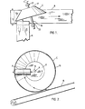
- a feed conveyor belt A is adapted to convey the material from a given source in a feed path in the direction of the arrow.
- a belt B is located below the delivery end of the belt A to run in a different or output path.
- means for transferring the material from the delivery end of the belt A to the receiving end of the belt B which includes a deflector C.
- the deflector C is made up of a dished or frusto conical wall 15 and a circular base 17.
- the deflector C is mounted at a hub H and its base 17 on a shaft 19 by suitable connecting means so that the deflector is rotatable.
- the shaft 19 is journalled in bearings 21 and 23 suitably mounted on a stable stationary structure (not shown).
- material for example, coarse sand
- the belt A In operation, material, for example, coarse sand, is conveyed by the belt A from a source of supply and delivered from its delivery end to the dished surface of the wall 15.
- the forward and gravitational movement of the material, spilled from the delivery end of the belt A, imparts energy to the cone C causing it to rotate.
- the material passes partly about the rotating surface of the cone C and spills from it onto the conveyor belt B with a forward and downward trajectory in the direction of travel of belt B.
- the direction of the material therefore, changes from the feed direction of the belt A to the output direction of the belt B, while maintaining energy imparted by momentum generated in it by the movement of the belt A and by gravity through the fall of the material from the level of the belt A to the level of the belt B.
- the contact of the material with the cone C thus imparts impelling spin to the latter which it translates, in the material, into linear force in the direction of the belt B.
- the deflector C is a dish which is free to rotate about its axis and with its concave side towards the first belt A, placed with its axis roughly in line with the belt A, or, at an angle in the horizontal plane, to the line of the belt A, say 0 0 to 30°, that it will receive the material on the inside surface of its wall 15 and deflect the material to move in the direction of the belt B and discharge it on the belt B moving in that direction.
- the deflector should be positioned to allow the material which is falling in its trajectory from the end pulley of the belt A to strike the surface of the dish C at an angle before being carried around on the working surface of the deflector towards the intended discharge direction and finally discharged from the dish C at about its lowest part or the part between the lowest point of the rim and another point about 50° from a vertical line down from the axis and following the direction of rotation.
- the material contacts the deflector C at one side of its axis and about the same height as its axis and at the side travelling downwards as the deflector rotates counterclockwise in Figures 1 and 2.
- the material while essentially describing an arc or spiral round the axis, under the action of gravity and centrifugal force, moves to the outside rim of the flared wall 15 and leaves the deflector C at a lower zone close to the belt B with the material travelling substantially in the desired direction of travel of the belt B.
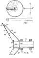
- FIGS 7, 8 and 9 illustrate possible variations in the setting of a deflector C relative to a feed belt A and receiving belt B, with the belts shown at right angles to each other for the sake of simplicity.
- X 1 -X 2 represents the arc of rotation of the deflector C in the horizontal plane about the hub H of the cone C, i.e. where the shaft 19 joins the base 17, through an angle p.
- Line L 1 -L 2 represents variations of the position of the hub of the deflector C laterally relative to the feed belt A.
- the line T+ represents the setback of the rim of the deflector from the central axis of the front pulley of the belt A.
- the line H 1 -H 2 represents variations in the vertical height of the deflector axis (at its hub) relative to the axis of the front pulley of the conveyor A.
- the arc Y 1 -Y 2 represents the arc of rotation of the deflector about the vertical axis of its hub through the angle t.
- M+ represents the vertical distance from the rim of the deflector to the surface of the receiving belt B.
- N the diameter of the deflector.
- P+ represents the distance from the centreline of the pulley of the receiving belt B to the rim of the deflector C.
- the outside rim of the deflector should be roughly in line with the receiving belt and at a small angle p to the receiving belt, of between 0° and 30°, with 15° being preferable, but not at the centre of the belt.
- the deflector C must be positioned back from the centre a certain distance (T+) to allow the flowing material to be centrally located on the belt B.
- the deflector C should be so positioned vertically that the lower rim is clear of the receiving belt (distance M+) by several inches, say between 1 inch and 12 inches.
- the preferred distance M+ will vary, depending on the size of the deflector C, the nature of material being handled, and the belt speed.
- a preferred position of the deflector C, if sticky substances have to be transferred, is for its axis to be inclined to the horizontal (angle t) by between 0° and 10°, with about 5° being preferable. This inclination to the horizontal steepens the angle of the side of the deflector at the lowest point of the rotation where the discharge is taking place and allows the material to flow more easily onto the receiving belt B.
- a preferred position of the deflector in a horizontal position is to have the axis of the dished working surface offset to the line of the first belt by an angle p of about 5° to 40°, with about 15° preferred.
- the size of the deflector will vary in accordance with the size of the belts being used in the system. Generally, when used for transporting substantial quantities of bulk material, the belts have a width in the region od 18 inches to 108 inches, with 36 inches to 84 inches common.
- the diameter N of the deflector should not be less than double the width of the belt, preferably not less than 10% greater than double. This would mean that with a first or feeder belt A of 72 inches in width, the deflector C should have a diameter N not less than 12 feet and preferably not less than 13 feet 3 inches.
- the wall 15 of the deflector should be between 30 o and 80° (angle t) to the axis, with 45° to 55° being preferable.
- the material used in the construction of the inner surface of the cone depends on the bulk material being handled on the conveyor belts. For example, crushed stone, iron ore, coal, gypsum, sand, etc., calls for a steel or similar abrasive- resistant material. If grain or other less abrasive material are being handled, forms of plastic or other low friction material could be used.
- the deflector is preferably self-powered, i.e. to permit the normal flow of material to cause the desired speed of rotation.
- the speed of rotation of the deflector C will be close to the speed of the material received. This will reduce frictional wear.
- the working surface of the deflector must, on the one hand, have'a coefficient of friction high enough for the material fed to it to cause its rotation. On the other hand, the coefficient of friction must not be high enough to interfere with the sliding of the material from the deflector surface, degradation of the product, and also degradation of the deflector itself.
- the rotatable mounting of the deflector C may be varied to suit the circumstances.
- the deflector C may be fitted with and be supported by a bearing shaft 19 protruding outward and away from its hub R apex and in line with its axis. Two or more bearings on this shaft may be used.
- a bearing collar or track 20 around the sloped side, but in a plane parallel to the rim of the deflector C, may be fitted and only one shaft bearing 21c may be necessary. Wheels 22 mounted on shaft 22a journalled from a fixed structure are provided to bear against the collar or track 20.
- the deflector C may be mounted and supported by a shaft 19 in line with its axis and which protrudes out from both ends. Such mountings would require a bearing 21b at one end and a bearing 23b at the other end.
- the deflector C is mounted and supported by two or more bearings 21e, 23e on a shaft 19 in line with the axis and protruding only on the side away from the hub as in Figure 5.
- This configuration is advantageous if there are space constraints at the reverse side of the deflector C, for example, on shipboard.
- Deflector - Alternative Constructions Various deflector shapes are also possible.
- the normal apex or point of a frusto-conical deflector 15a is replaced with a frusto-spherical part 17a, see Figure 3.
- the sides of such part sphere is tangential to and welded or fixed to the sides of the remaining part of the deflector.
- Such a combined design of cone and sphere eliminates the probability of material collecting at the centre where centrifugal forces are minimal and also allows overloads to be more efficiently handled.
- Amother design of revolving receptacle is part of a sphere (less than half) mounted in a similar manner as described previously.
- a number of combinations of straight sides or curved surfaces may be used to provide the saucer or bowl effect required to turn the material in essentially one curved path towards the direction required. Examples are shown in Figures 3 to 6.
- Figure 11 is a diagrammatic illustration employing more than one deflector.
- a feed belt A 1 is disposed perpendicularly to a receiving belt B 1 .
- Deflectors C 1 and C 21 in parallel, deflect material passing from the feed belt A 1 onto the receiving belt B 1 .
- belts ranging in width between 12 inches and about 108 inches with 36 to 84 inches preferred. These belts will usually travel at 150 feet per minute to 1200 feet per minute, with 200 to 800 feet per minute being a preferred orange. Generally, such belts handle between about 200 tons per hour to 20,000 tons per hour, with 1,000 to 10,000 being common.
- Figure 12 illustrates another arrangement in which the deflect is provided with means for removing material from the working surface.
- a brush-type conveyor belt cleaner W is shown.
- the reference numerals given to the other parts are similar to those in previous figures except that the 100's unit has been raised.
- the deflector may be adjustably mounted so that it can be moved to various positions and attitudes as suggested above.
- the deflector may be mounted in a fixed position and fixed attitude with respect to the belts.
- the invention contemplates a procedure in which the deflector is mounted to permit it to be moved vertically and horizontally and for its attitude to be altered by rotating it about its hub both in the horizontal and vertical plane and data accumulated on its performance in the various positions. The resulting data can then be employed to install a deflector having an ideal fixed position and fixed attitude.
- Figure 13 illustrates another application of the invention to conveyors of the type disclosed in the U.L.S. Upper Lakes Shipping Ltd. literature on self-unloading ships and the illustration entitled "Hopper Type Self-Unloading Bulk Carrier".
- the hull of the ship is illustrated as R.
- the tunnel belts 215 discharge respectively onto deflectors C 5 and C 6 which, in turn, deliver the material to a loop belt conveyor 220 which, in turn, discharges the material onto a boom belt conveyor 226.
- the overall arrangement is well known except for the use of the deflectors in place of a pair of transversely extending conveyors which would normally deliver the material from the tunnel belt conveyors 215 to the loop belt conveyor 220. Considerable saving in power and space is achieved by this arrangement.
- the working wall of the deflector is made up of a frusto conical steel plate 217 and an extension in the form of another frusto conical steel plate 219 faced with a ceramic surface 221.
- the plate 217 is welded as at 222 to a base plate 223 bolted to a ring 224 which, in turn, is connected to the shaft 225.
- Radial T-stiffeners 227 are provided at intervals about the rear face of the working wall.
- Rolled angles 229 and 231 extend in the.circumferential direction about the reverse face of the working wall 215.
- a ring 233 is welded to the outer edge of the working wall 215 to provide a rim.
- the stiffeners 227 are connected to a ring 237 extending about the shaft 225.
- the shaft 225 is carried by bearings 239 and 240 which are suitably housed and supported from a strong stable supporting structure (not shown).
Landscapes
- Engineering & Computer Science (AREA)
- Mechanical Engineering (AREA)
- Structure Of Belt Conveyors (AREA)
- Intermediate Stations On Conveyors (AREA)
- Manufacturing And Processing Devices For Dough (AREA)
- Relays Between Conveyors (AREA)
- Ship Loading And Unloading (AREA)
Applications Claiming Priority (2)
| Application Number | Priority Date | Filing Date | Title |
|---|---|---|---|
| CA376447 | 1981-04-28 | ||
| CA000376447A CA1164898A (fr) | 1981-04-28 | 1981-04-28 | Transporteur |
Publications (2)
| Publication Number | Publication Date |
|---|---|
| EP0063951A2 true EP0063951A2 (fr) | 1982-11-03 |
| EP0063951A3 EP0063951A3 (fr) | 1983-03-30 |
Family
ID=4119847
Family Applications (1)
| Application Number | Title | Priority Date | Filing Date |
|---|---|---|---|
| EP82302151A Ceased EP0063951A3 (fr) | 1981-04-28 | 1982-04-27 | Méthode et appareil de convoyage de materiel |
Country Status (5)
| Country | Link |
|---|---|
| US (1) | US4502590A (fr) |
| EP (1) | EP0063951A3 (fr) |
| JP (1) | JPS582121A (fr) |
| AU (1) | AU554955B2 (fr) |
| CA (1) | CA1164898A (fr) |
Cited By (1)
| Publication number | Priority date | Publication date | Assignee | Title |
|---|---|---|---|---|
| WO2018213870A1 (fr) * | 2017-05-22 | 2018-11-29 | Narbel Pty Ltd | Appareil et procédé de dérivation de flux |
Families Citing this family (4)
| Publication number | Priority date | Publication date | Assignee | Title |
|---|---|---|---|---|
| US4974518A (en) * | 1988-08-01 | 1990-12-04 | Oak Industries, Inc. | Automatic tie plate setting machine |
| DE102011105887A1 (de) * | 2011-06-27 | 2012-12-27 | Focke & Co. (Gmbh & Co. Kg) | Vorrichtung und Verfahren zum Gruppieren von Gegenständen |
| JP5772520B2 (ja) * | 2011-11-07 | 2015-09-02 | Jfeスチール株式会社 | ベルトコンベヤ蛇行防止装置 |
| DE102012214185A1 (de) * | 2012-08-09 | 2014-02-13 | Krones Ag | Verfahren und Vorrichtung zur Förderung von Fördergut mit einer Zellenradschleuse |
Family Cites Families (7)
| Publication number | Priority date | Publication date | Assignee | Title |
|---|---|---|---|---|
| DD14755A (fr) * | ||||
| DE483969C (de) * | 1928-06-07 | 1929-10-08 | A T G Allg Transportanlagen Ge | Vorrichtung zur UEberladung von Foerdergut |
| FR1096554A (fr) * | 1953-12-21 | 1955-06-22 | Nouveau dispositif de manutention | |
| DE1106684B (de) * | 1958-02-28 | 1961-05-10 | Gerhard Norbutat | UEbergabe- und Aufgabevorrichtung fuer Schuettgut auf ein Foerderband |
| DE1917777U (de) * | 1964-03-10 | 1965-06-10 | Oppermann & Deichmann Maschine | Vorrichtung zum vermindern der abwurfgeschwindigkeit von foerdergut beim verlassen des abgabeendes eines foerderers. |
| US4072238A (en) * | 1976-11-24 | 1978-02-07 | Allis-Chalmers Corporation | Self-unloading ship with two tunnel belts and a central reclaimer |
| DE8124756U1 (de) * | 1981-08-25 | 1982-01-07 | Ruhrkohle Ag, 4300 Essen | Einrichtung zur uebergabe von schuettgut |
-
1981
- 1981-04-28 CA CA000376447A patent/CA1164898A/fr not_active Expired
-
1982
- 1982-04-19 AU AU82806/82A patent/AU554955B2/en not_active Ceased
- 1982-04-27 EP EP82302151A patent/EP0063951A3/fr not_active Ceased
- 1982-04-28 JP JP57072529A patent/JPS582121A/ja active Pending
-
1984
- 1984-05-25 US US06/614,116 patent/US4502590A/en not_active Expired - Fee Related
Cited By (1)
| Publication number | Priority date | Publication date | Assignee | Title |
|---|---|---|---|---|
| WO2018213870A1 (fr) * | 2017-05-22 | 2018-11-29 | Narbel Pty Ltd | Appareil et procédé de dérivation de flux |
Also Published As
| Publication number | Publication date |
|---|---|
| AU8280682A (en) | 1982-11-04 |
| EP0063951A3 (fr) | 1983-03-30 |
| JPS582121A (ja) | 1983-01-07 |
| US4502590A (en) | 1985-03-05 |
| AU554955B2 (en) | 1986-09-11 |
| CA1164898A (fr) | 1984-04-03 |
Similar Documents
| Publication | Publication Date | Title |
|---|---|---|
| US5415322A (en) | Machine for automatically positioning and aligning containers | |
| US4007854A (en) | Apparatus for feeding articles in serial order | |
| US3049215A (en) | Single row feeder | |
| US3592394A (en) | Centrifugal belt thrower | |
| US4502590A (en) | Conveyor apparatus | |
| US3900107A (en) | Rotating method of sorting particulate articles | |
| CN87101899A (zh) | 真空抛射粉碎机轮盘 | |
| US20040182673A1 (en) | Transfer chute and method of operating the chute | |
| US2788115A (en) | Distributor for silos | |
| CA3047866C (fr) | Convoyeur empileur-ramasseur | |
| EP0287171B1 (fr) | Transporteur | |
| JPH05500789A (ja) | 遠心投射可能な材料を供給部から所定現場に導管なしで移送するための装置 | |
| US3887062A (en) | Side entry hopper for rotary fruit feeder | |
| US3071295A (en) | Bulk feeding apparatus | |
| US3578140A (en) | Closure feeding apparatus | |
| US3332534A (en) | Material handling device | |
| US4646910A (en) | Generalized high speed belt to belt transfer chute | |
| US3061074A (en) | Rotary conveyor | |
| WO2001045846A1 (fr) | Rotor avec guide pourvu d'un bord d'alimentation | |
| US4941295A (en) | Abrasive elevating apparatus for blast machines and method of using | |
| US3355005A (en) | Loading device and method for transfer points | |
| EP0163972A2 (fr) | Système d'évacuation pour broyeur | |
| CN219817095U (zh) | 配速设备及干选系统 | |
| US3561823A (en) | Metering and separating means for a conveyer system | |
| US2710148A (en) | Pulverizer grinding rings |
Legal Events
| Date | Code | Title | Description |
|---|---|---|---|
| PUAI | Public reference made under article 153(3) epc to a published international application that has entered the european phase |
Free format text: ORIGINAL CODE: 0009012 |
|
| AK | Designated contracting states |
Designated state(s): AT BE CH DE FR GB IT LI LU NL SE |
|
| PUAL | Search report despatched |
Free format text: ORIGINAL CODE: 0009013 |
|
| AK | Designated contracting states |
Designated state(s): AT BE CH DE FR GB IT LI LU NL SE |
|
| 17P | Request for examination filed |
Effective date: 19830826 |
|
| STAA | Information on the status of an ep patent application or granted ep patent |
Free format text: STATUS: THE APPLICATION HAS BEEN REFUSED |
|
| 18R | Application refused |
Effective date: 19860328 |