EP0064164A2 - Dispositif pour l'accouplement et le relâchement rapide d'un disque porte-caractères dans une machine à écrire - Google Patents
Dispositif pour l'accouplement et le relâchement rapide d'un disque porte-caractères dans une machine à écrire Download PDFInfo
- Publication number
- EP0064164A2 EP0064164A2 EP82102920A EP82102920A EP0064164A2 EP 0064164 A2 EP0064164 A2 EP 0064164A2 EP 82102920 A EP82102920 A EP 82102920A EP 82102920 A EP82102920 A EP 82102920A EP 0064164 A2 EP0064164 A2 EP 0064164A2
- Authority
- EP
- European Patent Office
- Prior art keywords
- daisy wheel
- wheel element
- resilient means
- fact
- drive unit
- Prior art date
- Legal status (The legal status is an assumption and is not a legal conclusion. Google has not performed a legal analysis and makes no representation as to the accuracy of the status listed.)
- Withdrawn
Links
- 241000723353 Chrysanthemum Species 0.000 title claims abstract description 62
- 235000005633 Chrysanthemum balsamita Nutrition 0.000 title claims abstract description 62
- 230000008878 coupling Effects 0.000 title claims abstract description 15
- 238000010168 coupling process Methods 0.000 title claims abstract description 15
- 238000005859 coupling reaction Methods 0.000 title claims abstract description 15
- 230000007246 mechanism Effects 0.000 claims description 3
- 210000002105 tongue Anatomy 0.000 description 5
- 238000006073 displacement reaction Methods 0.000 description 3
- 230000005540 biological transmission Effects 0.000 description 1
- 238000006243 chemical reaction Methods 0.000 description 1
- 230000000694 effects Effects 0.000 description 1
- 230000002093 peripheral effect Effects 0.000 description 1
- 238000003466 welding Methods 0.000 description 1
Images
Classifications
-
- B—PERFORMING OPERATIONS; TRANSPORTING
- B41—PRINTING; LINING MACHINES; TYPEWRITERS; STAMPS
- B41J—TYPEWRITERS; SELECTIVE PRINTING MECHANISMS, i.e. MECHANISMS PRINTING OTHERWISE THAN FROM A FORME; CORRECTION OF TYPOGRAPHICAL ERRORS
- B41J7/00—Type-selecting or type-actuating mechanisms
-
- B—PERFORMING OPERATIONS; TRANSPORTING
- B41—PRINTING; LINING MACHINES; TYPEWRITERS; STAMPS
- B41J—TYPEWRITERS; SELECTIVE PRINTING MECHANISMS, i.e. MECHANISMS PRINTING OTHERWISE THAN FROM A FORME; CORRECTION OF TYPOGRAPHICAL ERRORS
- B41J1/00—Typewriters or selective printing mechanisms characterised by the mounting, arrangement or disposition of the types or dies
- B41J1/22—Typewriters or selective printing mechanisms characterised by the mounting, arrangement or disposition of the types or dies with types or dies mounted on carriers rotatable for selection
- B41J1/24—Typewriters or selective printing mechanisms characterised by the mounting, arrangement or disposition of the types or dies with types or dies mounted on carriers rotatable for selection the plane of the type or die face being perpendicular to the axis of rotation
- B41J1/243—Mounting or fixing the carriers
Definitions
- the present invention relates to a device for rapid coupling and r eleasing of a character support member of the daisy wheel type in a typewriter.
- Character support members of the daisy wheel type are, as is known, constituted substantially by a circular flat element having a central hub from which extend radial projections commonly called "petals". On the end of each projection there is formed a character which from time to time is pressed against the surface of the sheet to be typed carried by the roller of the machine by means of a suitable type bar.
- the daisy wheel support member is connected to a drive element which causes the member to rotate about its axis in such a way that the character which is to be impressed on the sheet to be typed is selected at the appropriate time.
- the object of the present invention is that of providing a device for rapidly coupling and releasing a character support member of the daisy wheel type which will be substantially free from the disadvantages of the known devices described above, and which will be simple to use whilst at the same time permitting an extremely precise positioning of the daisy wheel support member with respect to the associated drive element.
- the said object is achieved with the present invention in that it relates to a typewriter utilising a daisy wheel element as the typing member, and having a drive unit which drives the daisy wheel element to rotate about its axis and which also serves as a support element for the said daisy wheel element, and a device for coupling the said daisy wheel element to the said drive unit, characterised by the fact that the said coupling device comprises:
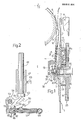
- a daisy wheel element is generally indicated with the reference numeral 1; this is driven to rotate about its own axis by means of a drive unit 2.
- the daisy wheel element 1 is of a substantially known type and has a circular hub 3 with an axial through hole 4 in which is fitted a bush 5; from the outer surface of the hub 3 radial projections commonly called “petals” and indicated with the reference numeral 6, extend radially outwardly; each of these petals carries at its radially outer end a portion 7 on which a predetermined type character is impressed.
- a type bar is generally indicated with the reference numeral 8; this is operated in a manner which is not illustrated in the drawings to cause the end 7 of each petal 6 to be pressed against the facing surface of a roller 9 on which, in use, there is carried a sheet to,be typed.
- the reference numerals 10 and 11 indicate two shaped elements of known type which, respectively, allow the sheet to be typed to be held correctly pressed on the surface of the roller 9 and guide the typewriter ribbon in front of each end portion 7 of the above mentioned daisy wheel element 1.
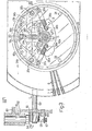
- the drive unit 2 substantially comprises a disc 14 and a spindle 15 which carries the disc 14 and to which a hub 16 of the disc 14 itself is angularly coupled. From the hub 16 of the disc 14 there extends radially a radial rib 17 (see also Figure 3) which serves as a guide for two projections which extend parallel to one another and substantially radially of the hub 3 of the daisy wheel element 1.
- the radial rib 17 has a root 19 and an end portion 20 which both have a width greater than an intermediate rectilinear section 21; moreover, the end portion 20 has rounded edges (see also Figure 3).
- Each radial projection 18a, 18b cooperates with the rib 17 only at the root 19 and the end portion 20 of this latter, and has, moreover, a respective outwardly extending tongue 22a, 22b which is engageable on the surface of the hub 16 of the disc 14.
- the disc 14 also has a pair of projections 23, 24 which, together with the end portion 20 of the radial rib 17 constitute a set of three elements disposed equi-distantly around a circumference and defining a contact plane for the hub 3 of the daisy wheel element 1. Finally, on the peripheral surface of the disc 14 there are formed teeth 25 which, in a manner not illustrated, are conveniently engaged by a pinion of a small motor (not illustrated) which controls the rotation of the disc 14 about the spindle 15.
- a device 30 which controls the coupling or releasing of the daisy wheel element 1 with respect to the drive unit 2 and which is. substantially constituted by a first assembly 31 of resilient means carried by the drive unit 2 and acting on the surface of the daisy wheel element 1 on the side facing the unit 2, and by a second assembly 32 of resilient means provided with respective movement transmission mechanisms which act on the surface of the daisy wheel element 1 on the side opposite that facing the drive unit 2.
- the resilient means 31 are clearly visible in Figures 3 and 4 and are substantially constituted by a pair of levers 34a, 34b each of which is rotatably mounted about a respective pivot 35a, 35b against a resilient action exerted by a biasing spring 36a, 36b. These latter are anchored at a first end to a respective projection 37a, 37b extending from the levers 34a, 34b and at an opposite end to a peg 38a, 38b extending from the disc 14.
- each lever 34a, 34b which is conveniently made of a resiliently deformable material, has an arm 39a, 39b subtantially constituted by a flat part 40a, 40b and by a raised portion 41 a, 41b folded at 90° with respect to the above mentioned flat part 40a, 40b.
- Each portion 41 a, 41b has, moreover, at its end a respective tooth 42a, 42b for cooperating with the tongue 22a, 22b respectively of the parallel projections 18a, 18b extending from the hub 3 of the daisy wheel element 1.
- two stop elements 43a, 43b are provided, each of which prevents a respective lever 34a, 34b from being able to rotate beyond a certain angle under the resilient action exerted by the spring 36a, 36b.
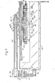
- the resilient means 32 substantially comprise a cap 46 having a flat top wall 47 and toothed projections 48 which snap-engage the cap 46 to the rounded head 49 of a pin 50 carried by a plate 51, as will be seen below, the head 47 of the cap 46 is resiliently thrust against the bush 5 of the daisy wheel element 1 in such a way that the hole 4 of the bush 5 itself is engaged by a head 52 projecting from the pin 15 of the drive unit 2 beyond the surface of the hub 16 of the disc 14.
- the plate 51 at the end opposite that carrying the pin 50 is connected, preferably by means of welding, to an end portion of a shaft 53 which carries at its opposite end a bell crank lever 54 having two arms 55, 56 extending at right angles to one another.
- the arm 55 is connected by means of a spring 57 to a peg 58;
- the arm 56 has a rounded end portion 59 against which abuts an enlarged head 60 of a cylindrical push rod 61.
- This latter can slide within a tubular guide 62 connected to a wall 63 of a support frame 64.
- a peg 65 which serves as a stop against, clockwise angular displacements of the arm 56 of the lever 54.
- the length of the push rod 61 is such that it can easily be actuated, in particular thrust in a longitudinal direction, by the user of the typewriter.
- the hub 3 of the daisy wheel element 1 is stressed by two resilient forces of opposite sign, the first of which is that exerted by the head 47 of the cap 46 by the effect of the above mentioned spring 57 and the second of which is exerted by the pair of folded over portions 41a, 41b of the levers 34a, 34b.
- the values of these two forces of opposite sign will have to be conveniently set in such a way that the resilient force on the hub 3 generated by the spring 57 predominates so that the hub 3 of the daisy wheel element 1 is held constantly in position on the projections 23,and 24 and on the end portion 20 of the rib 17.
- the coupling of a new daisy wheel element 1 is effected by inserting this element in such a way that the radial guide projections 18a, 18b engage the radial rib 17.
- the tongues 22a, 22b. abut on the respective teeth 42a, 42b it is necessary to exert a force by pressing downwardly from above on the daisy wheel element 1 (see Figures 1 and 4) in such a way as to overcome the resilient reaction exerted by the springs 36a, 36b.
- the push rod 61 is held constantly pressed.
- the device 30 in fact allows coupling and uncoupling of the element 1 in an extremely rapid and simple manner, it being in fact sufficient to press the push rod 61.
- the positioning of the element 1 is now extremely precise in that it is guaranteed by the elements 23, 24 and by the end portion 20 of the radial rib 17 which also performs the function of driving the daisy wheel element 1.
Landscapes
- Common Mechanisms (AREA)
- Accessory Devices And Overall Control Thereof (AREA)
- Mechanical Operated Clutches (AREA)
Applications Claiming Priority (2)
| Application Number | Priority Date | Filing Date | Title |
|---|---|---|---|
| IT6758881 | 1981-04-30 | ||
| IT8167588A IT8167588A0 (it) | 1981-04-30 | 1981-04-30 | Dispositivo per innesto disinnesto rapido di un organo di supporto caratteri del tipo a margherita in una macchina per scrivere |
Publications (2)
| Publication Number | Publication Date |
|---|---|
| EP0064164A2 true EP0064164A2 (fr) | 1982-11-10 |
| EP0064164A3 EP0064164A3 (fr) | 1983-09-07 |
Family
ID=11303657
Family Applications (1)
| Application Number | Title | Priority Date | Filing Date |
|---|---|---|---|
| EP82102920A Withdrawn EP0064164A3 (fr) | 1981-04-30 | 1982-04-06 | Dispositif pour l'accouplement et le relâchement rapide d'un disque porte-caractères dans une machine à écrire |
Country Status (11)
| Country | Link |
|---|---|
| US (1) | US4389130A (fr) |
| EP (1) | EP0064164A3 (fr) |
| JP (1) | JPS5833469A (fr) |
| KR (1) | KR830009943A (fr) |
| BR (1) | BR8202392A (fr) |
| DD (1) | DD202837A5 (fr) |
| ES (1) | ES8304849A1 (fr) |
| GB (1) | GB2097727B (fr) |
| IN (1) | IN157883B (fr) |
| IT (1) | IT8167588A0 (fr) |
| YU (1) | YU91082A (fr) |
Families Citing this family (6)
| Publication number | Priority date | Publication date | Assignee | Title |
|---|---|---|---|---|
| GB2135246B (en) * | 1983-02-23 | 1987-05-13 | Ricoh Kk | Daisy wheel supporting structure |
| IT1158811B (it) * | 1983-02-28 | 1987-02-25 | Olivetti & Co Spa | Dispositivo per accoppiare un disco portacaratteri ad un motore di selezione |
| EP0121970A1 (fr) * | 1983-04-07 | 1984-10-17 | Daisy Systems Holland B.V. | Dispositif pour la mise en place d'une marguerite dans une imprimante à marguerite et marguerite |
| DE3606545C1 (de) * | 1986-02-28 | 1987-04-16 | Triumph Adler Ag | Vorrichtung zum Kuppeln eines Typenrades mit einer Dreheinstellwelle in Schreib- oder aehnlichen Maschinen |
| US4881839A (en) * | 1988-06-14 | 1989-11-21 | Texas Instruments Incorporated | Portable electronic data handling/data entry system |
| GB2438405A (en) * | 2006-05-22 | 2007-11-28 | Nicholas Victor Sills | Underwater trenching and excavation apparatus |
Family Cites Families (9)
| Publication number | Priority date | Publication date | Assignee | Title |
|---|---|---|---|---|
| IT986534B (it) * | 1973-06-19 | 1975-01-30 | Olivetti & Co Spa | Dispositivo di scrittura in serie con disco portacaratteri alamine flessibili |
| IT1016552B (it) * | 1974-07-10 | 1977-06-20 | Olivetti & Co Spa | Dispositivo di fissaggio di un disco portacaratteri a lamine flessibili |
| DE2639872C2 (de) * | 1976-09-04 | 1978-09-21 | Olympia Werke Ag, 2940 Wilhelmshaven | Schreibwerk mit einer Typenscheibe |
| US4124312A (en) * | 1977-02-10 | 1978-11-07 | Xerox Corporation | Impact printer with print wheel cartridge |
| US4127335A (en) * | 1977-02-10 | 1978-11-28 | Xerox Corporation | Impact printer with cartridge print wheel |
| DE2822313C2 (de) * | 1978-05-22 | 1985-07-04 | Olympia Werke Ag, 2940 Wilhelmshaven | Typenradkassette für Schreib- oder ähnliche Büromaschinen |
| US4209262A (en) * | 1978-11-15 | 1980-06-24 | Xerox Corporation | Print wheel loading apparatus |
| DE2924360A1 (de) * | 1979-06-16 | 1980-12-18 | Olympia Werke Ag | Druckwerk fuer eine schreib- o.ae. bueromaschine mit einer typenscheibe |
| DE2950071C2 (de) * | 1979-12-13 | 1987-02-12 | Olympia AG, 2940 Wilhelmshaven | Vorrichtung zum Wechseln einer Typenscheibe in einem Druckwerk für eine Schreib- oder ähnliche Büromaschine mit einer Typenscheibe |
-
1981
- 1981-04-30 IT IT8167588A patent/IT8167588A0/it unknown
-
1982
- 1982-04-06 EP EP82102920A patent/EP0064164A3/fr not_active Withdrawn
- 1982-04-08 US US06/366,563 patent/US4389130A/en not_active Expired - Fee Related
- 1982-04-14 IN IN302/DEL/82A patent/IN157883B/en unknown
- 1982-04-23 GB GB8211888A patent/GB2097727B/en not_active Expired
- 1982-04-26 BR BR8202392A patent/BR8202392A/pt not_active IP Right Cessation
- 1982-04-26 JP JP57070156A patent/JPS5833469A/ja active Pending
- 1982-04-27 YU YU00910/82A patent/YU91082A/xx unknown
- 1982-04-29 ES ES511804A patent/ES8304849A1/es not_active Expired
- 1982-04-29 DD DD82239427A patent/DD202837A5/de unknown
- 1982-04-30 KR KR1019820001913A patent/KR830009943A/ko not_active Withdrawn
Also Published As
| Publication number | Publication date |
|---|---|
| KR830009943A (ko) | 1983-12-24 |
| DD202837A5 (de) | 1983-10-05 |
| BR8202392A (pt) | 1983-04-12 |
| JPS5833469A (ja) | 1983-02-26 |
| IT8167588A0 (it) | 1981-04-30 |
| US4389130A (en) | 1983-06-21 |
| ES511804A0 (es) | 1983-03-16 |
| EP0064164A3 (fr) | 1983-09-07 |
| YU91082A (en) | 1985-04-30 |
| GB2097727B (en) | 1985-05-30 |
| ES8304849A1 (es) | 1983-03-16 |
| GB2097727A (en) | 1982-11-10 |
| IN157883B (fr) | 1986-07-12 |
Similar Documents
| Publication | Publication Date | Title |
|---|---|---|
| US4127335A (en) | Impact printer with cartridge print wheel | |
| AU622211B2 (en) | Web holding device | |
| US4314770A (en) | Detachable connection assembly for a printing element in an electric office machine | |
| US4389130A (en) | Device for coupling and releasing a daisy wheel type member | |
| US4161373A (en) | Typing device including a type disc | |
| EP0336870B1 (fr) | Imprimante comportant un mécanisme pour régler l'espacement de la tête d'impression | |
| EP0066689B1 (fr) | Mécanisme pour changer le régime d'avance d'un ruban | |
| EP0082296B1 (fr) | Ensemble de rouleau d'alimentation en papier pour machine à écrire ou imprimante | |
| US5163764A (en) | Cartridge for a typing ribbon having a ribbon tensioner | |
| US4247212A (en) | Printer flaten clutch | |
| JPS6127748Y2 (fr) | ||
| CA1147201A (fr) | Composeuse | |
| EP0021099B1 (fr) | Mécanisme d'échappement et de retour en arrière à pas multiples pour machine à écrire à chariot porte-papier mobile | |
| EP0038691B1 (fr) | Imprimante d'impact ayant une roue amovible d'impression | |
| SU663284A3 (ru) | Буквопечатающее устройство | |
| US4810115A (en) | Character selecting mechanism | |
| US4359287A (en) | Impression control mechanism for a typewriter | |
| EP0063720A2 (fr) | Mécanisme de contrôle de position pour une cartouche de ruban encreur dans une machine à écrire | |
| US4804282A (en) | Character selecting mechanism | |
| CA1283576C (fr) | Mecanisme d'impression | |
| US4902148A (en) | Typewriter with a print wheel and hammer driven by one motor | |
| KR830001578Y1 (ko) | 활자 선택기구 | |
| JP2842047B2 (ja) | サーマルラインプリンタ | |
| US4420267A (en) | Serial printer | |
| KR100332052B1 (ko) | 드래그 제동 기구 및 클러치를 갖는 스피닝 릴 |
Legal Events
| Date | Code | Title | Description |
|---|---|---|---|
| PUAI | Public reference made under article 153(3) epc to a published international application that has entered the european phase |
Free format text: ORIGINAL CODE: 0009012 |
|
| AK | Designated contracting states |
Designated state(s): CH DE FR IT NL SE |
|
| PUAL | Search report despatched |
Free format text: ORIGINAL CODE: 0009013 |
|
| AK | Designated contracting states |
Designated state(s): CH DE FR IT LI NL SE |
|
| 17P | Request for examination filed |
Effective date: 19840221 |
|
| STAA | Information on the status of an ep patent application or granted ep patent |
Free format text: STATUS: THE APPLICATION HAS BEEN WITHDRAWN |
|
| 18W | Application withdrawn |
Withdrawal date: 19851216 |
|
| RIN1 | Information on inventor provided before grant (corrected) |
Inventor name: GIOLITTI, NICOLO |