EP0064346A1 - Hubschrauber - Google Patents
Hubschrauber Download PDFInfo
- Publication number
- EP0064346A1 EP0064346A1 EP82301958A EP82301958A EP0064346A1 EP 0064346 A1 EP0064346 A1 EP 0064346A1 EP 82301958 A EP82301958 A EP 82301958A EP 82301958 A EP82301958 A EP 82301958A EP 0064346 A1 EP0064346 A1 EP 0064346A1
- Authority
- EP
- European Patent Office
- Prior art keywords
- gear
- helicopter
- rotation
- rotor
- rotor hub
- Prior art date
- Legal status (The legal status is an assumption and is not a legal conclusion. Google has not performed a legal analysis and makes no representation as to the accuracy of the status listed.)
- Withdrawn
Links
- 230000002093 peripheral effect Effects 0.000 description 3
- 230000000717 retained effect Effects 0.000 description 2
- 230000005540 biological transmission Effects 0.000 description 1
- 238000009434 installation Methods 0.000 description 1
- 230000013011 mating Effects 0.000 description 1
- 238000012986 modification Methods 0.000 description 1
- 230000004048 modification Effects 0.000 description 1
- 238000004904 shortening Methods 0.000 description 1
Images


Classifications
-
- B—PERFORMING OPERATIONS; TRANSPORTING
- B64—AIRCRAFT; AVIATION; COSMONAUTICS
- B64C—AEROPLANES; HELICOPTERS
- B64C27/00—Rotorcraft; Rotors peculiar thereto
Definitions
- THIS INVENTION relates to helicopters and more particularly to a helicopter including apparatus for mounting a stationary or independently rotatable device above a main sustaining rotor.
- the invention provides a helicopter having a main sustaining rotor comprising a rotor hub and a plurality of radially extending rotor blades arranged for rotation about a generally vertical axis and including apparatus for supporting a stationary or independently rotatable device above the rotor, wherein said apparatus comprises a first ring gear located below the rotor hub and supported from helicopter structure concentrically of the axis of rotation, a second ring gear above the rotor hub having the same number of gear teeth as the first gear, support means for supporting the second ring gear in a manner permitting relative rotation of the rotor hub, and synchronising means rotationally fixed to the rotor hub and meshing with said first and second gears.
- the synchronising means may comprise a pair of spaced-apart gear wheels rotationally fixed to each other and supported at the end of a yoke member extending radially from a fixed attachment to the rotor hub.
- the synchronising means comprises two pairs of spaced-apart gear wheels, the wheels of each pair being rotationally fixed to each other, respectively supported at the opposite ends of a yoke member extending across the axis of rotation and attached centrally to the rotor hub.
- the support means may comprise a central spigot located concentrically of the axis of rotation in axially spaced-apart bearings located in a housing rotationally fixed to the rotor hub.
- the housing supports an annular gear adapted to drive an electric generator supported by said second gear.
- the first gear is mounted on the helicopter structure for rotation around the axis of rotation, positioning means being provided and adapted to selectively rotate the first gear and said device in both directions independently of the rotation of the rotor hub.
- the positioning means may include a motor adapted to drive a gear wheel meshed with gear teeth on the first gear.
- the gear teeth on the first and second gears are formed on an internal surface thereof.
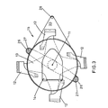
- a helicopter 10 has a main sustaining rotor arranged for rotation about an axis 11 and comprising four generally radially extending rotor blades 12 attached to a rotor hub 13.
- a sight 14 is located above the rotor hub 13 generally concentrically of axis 11, and is attached by mounting apparatus generally indicated at 15.
- FIGS 2, 3 and 4 illustrate the mounting apparatus 15 in greater detail.
- a first gear 16 having a plurality of peripheral gear teeth 35 is located below the rotor hub 13 concentrically of axis 11, and is rotatably mounted on a support structure 17 attached to helicopter structure.
- the gear 16 includes an annular toothed portion 18 concentric of .axis 11 and meshed with a gear wheel 19 carried by an electric motor 39 supported from structure 17.
- a second gear 20 is located above the rotor hub 13 concentrically of axis 11 and parallel to the first gear 16.
- Gear 20 is the same diameter as gear 16 and has peripheral gear teeth 36 equal in number to gear teeth 35 on gear 16.
- a radially inwardly extending portion of gear 20 terminates in a flange 24 that is bolted to an external surface of one end of a central spigot 37 ( Figure 4) which is supported in bearings 21 in a housing 22 rotationally fixed to the rotor hub 13.
- a gear 23 is attached to housing 22 and is meshed with an electric supply generator 34 supported by the radial portion of gear 20.
- the sight 14 is also bolted to the end of the spigot 37 ( Figure 4).
- Synchronising means includes a yoke 26 rotationally fixed to the rotor hub 13 and located so that its radially extending arms are positioned between adjacent arms of the rotor hub 13.
- a synchronising gear set generally indicated at 25 is supported at each end of the yoke 26, each of the gear sets 25 comprising a pair of axially spaced-apart gear wheels 27 rotationally fixed to each other and rotatably mounted in housing portions 28 carried by the yoke 26.
- the gear wheels 27 have identical numbers of peripheral gear teeth and the gear wheels 27 of each synchronising gear set 25 are meshed respectively with the gear teeth 35 and 36 of the first and second gears 16 and 20.
- yoke 26 has a central depending boss 26a bolted to an upper surface of the rotor hub 13.
- Housing 22 has upper and lower radial flanges, the lower of which provides for bolted attachment of the housing 22 to the yoke 26.
- the upper flange of housing 22 is bolted to a mating flange at a lower end of a further annular housing 38 whose upper end supports the integral gear 23 (see also Figure 2).
- a receiver unit 29 is mounted on a support flange 30 rotationally fixed to gear 16 and is aligned functionally with a transmitter unit 32 mounted on the head of the sight 14.
- a cable 33 is routed along flange 30 of the support structure 17 for connection to an amplifier and a C.R.T. (not shown).
- the embodiment illustrated in Figure 5 is similar to that previously described except that the gear teeth 35 and 36 (only the teeth 36 of the top gear 20 being shown in the illustration) are formed on an internal surface of the respective gears 16 and 20.
- the teeth are similarly meshed with gears 27 of the respective synchronising gear sets 25 and it is to be noted that the arrangement of Figure 5 results in a shortening of the length of yoke 26 compared with the previous embodiment, which therefore also reduces the weight, and the meshed gears are protected from the ingress of dirt and moisture.
- Yoke 26 and the attached synchronising gear sets 25 are rotated with the rotor hub 13 and attached rotor blades 12 about the axis 11. Since the wheels 27 of each synchronising gear set 25 are meshed respectively with the gear teeth 35 of stationary gear 16 and the gear teeth 36 of gear 20 that is supported by the central spigot 37 on bearings 21, the wheels 27 run around the periphery of gears 16 and 20, whereby the upper gear 20 is rotationally fixed to the stationary gear 16 and no rotary movement of gear 20 or spigot 37 occurs.
- the sight 14 is also supported from the spigot 37 and is thereby maintained stationary and in a desired direction of operation during rotation of the rotor hub 13.
- a further important feature of the invention is the provision of positioning means enabling the sight 14 to be selectively rotated about axis 11. This is achieved by energising motor 39 to rotate wheel 19 which is meshed with teeth 18 causing corresponding rotation of gear 16 about the axis 11. Rotation of the gear 16 is superimposed on the rotation of gear wheels 27 of the synchronising gear sets 25 and is transmitted thereby to cause a corresponding rotational movement of upper gear 20 and, therefore, the spigot 37 and the attached sight 14.
- the sight 14 can be selectively rotated in azimuth and can be selectively stopped and retained in a desired azimuthal position.
- Cable 33 is coiled around structure 17 so as to enable the sight 14 to be rotated through 270 degrees, i.e. 90 degrees in one direction from a datum forward-facing direction, and 180 degrees in the other direction.
- Rotation of the rotor hub 13 is transmitted through the yoke 26 and housings 22 and 38 to rotate gear 23 which drives the generator 34 to provide an electrical supply to power the transmitter/receiver unit 32 on the sight 14. Since gear 16 is always rotationally fixed to the sight 14, the respective transmitter/receiver units 29 and 32 are retained in functional alignment regardless of their azimuthal position.
- Any suitable means such as laser or micro-wave signal means may be used to transmit the necessary signals between transmitter/receiver units 29 and 32.
- the present invention enables a stationary or independently rotatable device, such as a sight or an aerial, to be mounted above the sustaining rotor of a helicopter, and does not rely on a hollow stationary shaft through the rotor and transmission.
- This invention therefore extends considerably the range of helicopters on which such a device can be fitted retrospectively, and does not restrict new designs of helicopter on which such a facility is desired to a design having such a hollow stationary central shaft.
- housing 22 could be formed integral with yoke 26 and could be formed with gear 23 to dispense with the separate housing 38.
- the range of permissible angular movement of the sight 14 can be extended to encompass 360 degrees with suitable routing of the cable 33.
Landscapes
- Engineering & Computer Science (AREA)
- Mechanical Engineering (AREA)
- Aviation & Aerospace Engineering (AREA)
- Toys (AREA)
- Retarders (AREA)
Applications Claiming Priority (2)
| Application Number | Priority Date | Filing Date | Title |
|---|---|---|---|
| GB8112941 | 1981-04-27 | ||
| GB8112941 | 1981-04-27 |
Publications (1)
| Publication Number | Publication Date |
|---|---|
| EP0064346A1 true EP0064346A1 (de) | 1982-11-10 |
Family
ID=10521393
Family Applications (1)
| Application Number | Title | Priority Date | Filing Date |
|---|---|---|---|
| EP82301958A Withdrawn EP0064346A1 (de) | 1981-04-27 | 1982-04-15 | Hubschrauber |
Country Status (2)
| Country | Link |
|---|---|
| US (1) | US4447023A (de) |
| EP (1) | EP0064346A1 (de) |
Cited By (2)
| Publication number | Priority date | Publication date | Assignee | Title |
|---|---|---|---|---|
| GB2256623A (en) * | 1991-06-12 | 1992-12-16 | Westland Helicopters | Mounting a device above a helicopter rotor. |
| EP0562899A1 (de) * | 1992-03-24 | 1993-09-29 | EUROCOPTER FRANCE, Société Anonyme dite: | Visiervorrichtung für Drehflügelflugzeug |
Families Citing this family (12)
| Publication number | Priority date | Publication date | Assignee | Title |
|---|---|---|---|---|
| JPH1159593A (ja) * | 1997-08-14 | 1999-03-02 | Fuji Heavy Ind Ltd | ヘリコプタの動力伝達装置 |
| US6122102A (en) * | 1998-02-20 | 2000-09-19 | Mcdonnell Douglas Corporation | Sighting apparatus for aiming an optical device |
| RU2150410C1 (ru) * | 1998-12-22 | 2000-06-10 | Таланов Борис Петрович | Вертолет |
| RU2152891C1 (ru) * | 1998-12-22 | 2000-07-20 | Таланов Борис Петрович | Вертолет |
| RU2241638C2 (ru) * | 2002-08-09 | 2004-12-10 | Открытое акционерное общество "Нефтяные контрольно-измерительные приборы" | Устройство для защиты от контактов с лопастями воздушного винта летательного аппарата |
| FR2893000B1 (fr) | 2005-11-09 | 2008-08-22 | Eurocopter France | Support amovible de capteur pour helicoptere a rotor creux. |
| USD559764S1 (en) * | 2006-01-19 | 2008-01-15 | Silverlit Toys Manufactory, Ltd. | Helicopter |
| USD561678S1 (en) * | 2006-01-19 | 2008-02-12 | Silverlit Toys Manufactory, Ltd. | Helicopter |
| WO2009088491A2 (en) * | 2008-01-02 | 2009-07-16 | Sikorsky Aircraft Corporation | Planetary de-rotation system for a shaft fairing system |
| DE202012102598U1 (de) * | 2012-07-13 | 2012-07-26 | Telefunken Radio Communication Systems Gmbh & Co. Kg | Anordnung mit wenigstens einer drehbaren Funktionseinheit |
| US20150122941A1 (en) * | 2013-11-06 | 2015-05-07 | Sikorsky Aircraft Corporation | Counter-rotating rotor system with fairing |
| US10974824B2 (en) * | 2017-07-20 | 2021-04-13 | Sikorsky Aircraft Corporation | Electric powered direct drive rotor motor |
Citations (4)
| Publication number | Priority date | Publication date | Assignee | Title |
|---|---|---|---|---|
| FR402272A (fr) * | 1908-08-24 | 1909-10-02 | Jules Grimaud | Embrayeur universel |
| GB353576A (en) * | 1930-05-15 | 1931-07-30 | British Thomson Houston Co Ltd | Improvements in and relating to speed controlling mechanism |
| US3570787A (en) * | 1968-08-30 | 1971-03-16 | Bernhardt Stahmer | Helicopter column for supporting multiblade rotors and summit loads |
| US4275992A (en) * | 1979-04-09 | 1981-06-30 | Textron, Inc. | Mode controlled attachment of rotor mounted components |
Family Cites Families (1)
| Publication number | Priority date | Publication date | Assignee | Title |
|---|---|---|---|---|
| US4277789A (en) * | 1979-07-27 | 1981-07-07 | Georgia Tech Research Institute | Microwave energy transmission system for around-the-mast applications |
-
1982
- 1982-04-13 US US06/367,960 patent/US4447023A/en not_active Expired - Fee Related
- 1982-04-15 EP EP82301958A patent/EP0064346A1/de not_active Withdrawn
Patent Citations (4)
| Publication number | Priority date | Publication date | Assignee | Title |
|---|---|---|---|---|
| FR402272A (fr) * | 1908-08-24 | 1909-10-02 | Jules Grimaud | Embrayeur universel |
| GB353576A (en) * | 1930-05-15 | 1931-07-30 | British Thomson Houston Co Ltd | Improvements in and relating to speed controlling mechanism |
| US3570787A (en) * | 1968-08-30 | 1971-03-16 | Bernhardt Stahmer | Helicopter column for supporting multiblade rotors and summit loads |
| US4275992A (en) * | 1979-04-09 | 1981-06-30 | Textron, Inc. | Mode controlled attachment of rotor mounted components |
Cited By (5)
| Publication number | Priority date | Publication date | Assignee | Title |
|---|---|---|---|---|
| GB2256623A (en) * | 1991-06-12 | 1992-12-16 | Westland Helicopters | Mounting a device above a helicopter rotor. |
| GB2256623B (en) * | 1991-06-12 | 1994-12-07 | Westland Helicopters | Helicopters |
| EP0562899A1 (de) * | 1992-03-24 | 1993-09-29 | EUROCOPTER FRANCE, Société Anonyme dite: | Visiervorrichtung für Drehflügelflugzeug |
| FR2689089A1 (fr) * | 1992-03-24 | 1993-10-01 | Eurocopter France | Dispositif de visée pour aéronef à voilure tournante. |
| US5461796A (en) * | 1992-03-24 | 1995-10-31 | Societe Anonyme Dite: Eurocopter France | Gunsight device for rotating-wing aircraft |
Also Published As
| Publication number | Publication date |
|---|---|
| US4447023A (en) | 1984-05-08 |
Similar Documents
| Publication | Publication Date | Title |
|---|---|---|
| US4447023A (en) | Apparatus for mounting a device above a helicopter rotor | |
| US4209789A (en) | Rotatable aerial installation mounted on a mast with remote mechanical drive | |
| EP0150985A3 (de) | Wasserfahrzeug mit abnehmbarem Unterwasserantriebselement | |
| GB2266996A (en) | Antenna support providing movement in two transverse axes. | |
| JPS63503591A (ja) | 双対永久磁石発電機の構造 | |
| WO2020084316A1 (en) | A drive train | |
| US10308355B2 (en) | Hub mounted vibration suppression system | |
| US4575039A (en) | Apparatus for positioning the plane of an apparatus table at an optional inclination | |
| US11724800B2 (en) | Vibration attenuator | |
| EP1532048B1 (de) | Radial betätigter steuermomentkreisel | |
| EP0409050B1 (de) | Vorrichtung zum Auswuchten einer sich drehenden Masse, insbesondere für Schleifscheiben | |
| US3327538A (en) | Two-axis case rotating gyroscope | |
| US10774925B2 (en) | Drive system for driving a component having an electric motor unit and a transmission unit | |
| CA1237503A (en) | Pulse wheel system | |
| FI65957B (fi) | Marint propelleraggregat | |
| WO1982004502A1 (en) | Antenna tower assembly and method | |
| CN114604436B (zh) | 一种倾转机构 | |
| EP0075407B1 (de) | Hubschrauberrotor | |
| JPH0666666A (ja) | といし車の不つりあい補正装置 | |
| US20190352000A1 (en) | Rotor for an aircraft capable of hovering | |
| US4360349A (en) | Marine transmission | |
| EP0288999B1 (de) | Industrieroboter | |
| US4450450A (en) | Antenna tower assembly | |
| WO2000027698A1 (en) | Rotor hub for rotating wing aircraft | |
| WO1993005363A1 (en) | Stabilized antenna system |
Legal Events
| Date | Code | Title | Description |
|---|---|---|---|
| PUAI | Public reference made under article 153(3) epc to a published international application that has entered the european phase |
Free format text: ORIGINAL CODE: 0009012 |
|
| AK | Designated contracting states |
Designated state(s): DE FR GB IT |
|
| 17P | Request for examination filed |
Effective date: 19830405 |
|
| STAA | Information on the status of an ep patent application or granted ep patent |
Free format text: STATUS: THE APPLICATION HAS BEEN WITHDRAWN |
|
| 18W | Application withdrawn |
Withdrawal date: 19840206 |
|
| RIN1 | Information on inventor provided before grant (corrected) |
Inventor name: REID, PETER |