EP0562899A1 - Visiervorrichtung für Drehflügelflugzeug - Google Patents
Visiervorrichtung für Drehflügelflugzeug Download PDFInfo
- Publication number
- EP0562899A1 EP0562899A1 EP93400619A EP93400619A EP0562899A1 EP 0562899 A1 EP0562899 A1 EP 0562899A1 EP 93400619 A EP93400619 A EP 93400619A EP 93400619 A EP93400619 A EP 93400619A EP 0562899 A1 EP0562899 A1 EP 0562899A1
- Authority
- EP
- European Patent Office
- Prior art keywords
- mast
- internal
- support
- head
- rotor
- Prior art date
- Legal status (The legal status is an assumption and is not a legal conclusion. Google has not performed a legal analysis and makes no representation as to the accuracy of the status listed.)
- Granted
Links
- 239000000725 suspension Substances 0.000 claims abstract description 10
- 230000005284 excitation Effects 0.000 claims abstract description 5
- 239000012528 membrane Substances 0.000 claims description 20
- 239000000463 material Substances 0.000 claims description 16
- 230000002787 reinforcement Effects 0.000 claims description 13
- 229920001971 elastomer Polymers 0.000 claims description 6
- 239000000806 elastomer Substances 0.000 claims description 6
- 230000010355 oscillation Effects 0.000 claims description 6
- 238000005452 bending Methods 0.000 claims description 3
- 238000006073 displacement reaction Methods 0.000 claims description 3
- 239000002184 metal Substances 0.000 claims description 2
- 238000005096 rolling process Methods 0.000 claims description 2
- 210000001364 upper extremity Anatomy 0.000 abstract 2
- 210000003414 extremity Anatomy 0.000 abstract 1
- 230000006978 adaptation Effects 0.000 description 2
- 230000021715 photosynthesis, light harvesting Effects 0.000 description 2
- 238000010008 shearing Methods 0.000 description 2
- 238000004073 vulcanization Methods 0.000 description 2
- 230000005540 biological transmission Effects 0.000 description 1
- 238000001914 filtration Methods 0.000 description 1
- 230000005693 optoelectronics Effects 0.000 description 1
- 210000000056 organ Anatomy 0.000 description 1
- 210000004417 patella Anatomy 0.000 description 1
Images


Classifications
-
- F—MECHANICAL ENGINEERING; LIGHTING; HEATING; WEAPONS; BLASTING
- F16—ENGINEERING ELEMENTS AND UNITS; GENERAL MEASURES FOR PRODUCING AND MAINTAINING EFFECTIVE FUNCTIONING OF MACHINES OR INSTALLATIONS; THERMAL INSULATION IN GENERAL
- F16M—FRAMES, CASINGS OR BEDS OF ENGINES, MACHINES OR APPARATUS, NOT SPECIFIC TO ENGINES, MACHINES OR APPARATUS PROVIDED FOR ELSEWHERE; STANDS; SUPPORTS
- F16M11/00—Stands or trestles as supports for apparatus or articles placed thereon ; Stands for scientific apparatus such as gravitational force meters
- F16M11/02—Heads
- F16M11/04—Means for attachment of apparatus; Means allowing adjustment of the apparatus relatively to the stand
- F16M11/06—Means for attachment of apparatus; Means allowing adjustment of the apparatus relatively to the stand allowing pivoting
- F16M11/12—Means for attachment of apparatus; Means allowing adjustment of the apparatus relatively to the stand allowing pivoting in more than one direction
- F16M11/14—Means for attachment of apparatus; Means allowing adjustment of the apparatus relatively to the stand allowing pivoting in more than one direction with ball-joint
-
- B—PERFORMING OPERATIONS; TRANSPORTING
- B64—AIRCRAFT; AVIATION; COSMONAUTICS
- B64C—AEROPLANES; HELICOPTERS
- B64C27/00—Rotorcraft; Rotors peculiar thereto
-
- F—MECHANICAL ENGINEERING; LIGHTING; HEATING; WEAPONS; BLASTING
- F16—ENGINEERING ELEMENTS AND UNITS; GENERAL MEASURES FOR PRODUCING AND MAINTAINING EFFECTIVE FUNCTIONING OF MACHINES OR INSTALLATIONS; THERMAL INSULATION IN GENERAL
- F16F—SPRINGS; SHOCK-ABSORBERS; MEANS FOR DAMPING VIBRATION
- F16F15/00—Suppression of vibrations in systems; Means or arrangements for avoiding or reducing out-of-balance forces, e.g. due to motion
- F16F15/02—Suppression of vibrations of non-rotating, e.g. reciprocating systems; Suppression of vibrations of rotating systems by use of members not moving with the rotating systems
- F16F15/04—Suppression of vibrations of non-rotating, e.g. reciprocating systems; Suppression of vibrations of rotating systems by use of members not moving with the rotating systems using elastic means
- F16F15/08—Suppression of vibrations of non-rotating, e.g. reciprocating systems; Suppression of vibrations of rotating systems by use of members not moving with the rotating systems using elastic means with rubber springs ; with springs made of rubber and metal
- F16F15/085—Use of both rubber and metal springs
Definitions
- the present invention relates to a sighting device for rotary wing aircraft, and more particularly to a helicopter, comprising a hollow rotor hub, on which blades are radially mounted constituting said rotary wing and which is connected to the main gearbox of the aircraft by a drive shaft coaxial with the rotor, said aiming device comprising a non-rotating aiming head mounted, by means of a support, at the free upper end of a non-rotating mast arranged coaxially to the inside said hub and said rotor drive shaft, mast whose other end is fixed in the bottom of the main gearbox, a bearing bearing coaxial with the rotor axis being provided between said hub and said mast.
- the present invention relates to a sighting device arranged to provide a better dynamic adaptation of the connecting structure of the sighting head on the hub so as to reduce its response to vibrational excitations generated by the rotating rotor.
- the aiming device of the type described above, is remarkable, according to the invention, in that suspension means, intended to filter the roll and pitch excitations to which said aiming head is subjected, are provided between the base of the aiming head support and the upper end of the mast.
- said suspension means comprise a ball joint in the form of a spherical zone, the center of which is located on the axis of the rotor and comprising flexible material fixed between two internal and external armatures, said external armature being integral with the base of the support.
- the aiming head and said internal frame being integral with the upper end of the mast.
- the layer of flexible material fixed between the two internal and external reinforcements is of the laminated type and consists of a plurality of layers of flexible material interposed between rigid spherical cups having the same center as the ball joint, on which cups said layers of flexible material are adhered.
- said flexible material can be an elastomer possibly having an energy dissipation capacity.
- said ball joint is coupled to a membrane in the form of a circular crown in a plane substantially parallel to the plane of the rotor, fixed, on the one hand, to its internal periphery, to the upper end of the mast and, on the other hand , at its external periphery, at the base of the support of the aiming head, said membrane being rigid in its own plane for transmitting the moments around the yaw axis and the coplanar forces, but allowing thanks to its flexibility in bending angular oscillations around the roll and pitch axes and the displacements along the yaw axis authorized by the relative axial flexibility of said ball joint.
- the yaw position of the aiming head is therefore transmitted by said membrane, practically without angular deformation.
- said membrane is fixed to the upper end of the mast and to the base of the support of the sighting head by means of said internal and external reinforcements, respectively.
- said membrane may include at least one circular rib. Furthermore, said membrane is advantageously a metal membrane.
- the device may include a stop means, constituted by a shoulder disposed at the base of the support of the aiming head and which comes to support the membrane on the internal reinforcement of the patella during angular oscillations around the rolling and pitching axes of the aiming head.
- Figure 1 is a sectional view of an aiming device for rotary wing of an aircraft according to the invention.
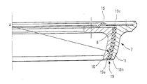
- FIG. 2 shows, on a larger scale, the base of the support of the aiming head and the upper end of the mast, with the suspension means according to the invention.
- Figure 3 is a sectional view of a variant of the ball joint in the form of a spherical zone according to the invention, in which the flexible material of the ball joint is of the laminated type, constituted by two layers of flexible material adhered to a spherical cup rigid midsole.
- the sighting device is intended to be mounted on the rotor of a rotary wing aircraft (not shown), such as a helicopter, which has a hollow rotor hub 1, represented by very schematically, on which blades are mounted radially (not shown) and which is supported and driven in rotation by the main gearbox 2 of the aircraft.
- the sighting device comprises, as is usual, a sighting head 3 mounted, by means of a support 4, at the free upper end 5a of a mast 5 arranged coaxially inside the hub 1, mast whose other end 5b is fixed in the bottom of the box housing main transmission.
- a bearing consisting of two ball bearings 6 is provided between the rotating hub 1 and the non-rotating mast 5.
- suspension means 7, intended to filter the excitations in roll (around the axis XX of FIG. 2) and in pitch (around the axis YY of FIG. 2) which is subject the aiming head 3, are provided between the base 4a of the support 4 of the aiming head 3 and the upper end 5a of the mast 5.
- the suspension means 7 comprise, in this embodiment, a ball joint 8 in the form of a spherical zone with center A located on the rotor axis, said spherical zone being parallel to the plane defined by the axes XX and YY, and comprising a layer 9 of flexible material, in particular an elastomer possibly having an energy dissipation capacity, fixed between two internal 10 and external 11 reinforcements, for example metallic (the elastomer layer being able to be adhered to the reinforcements 10 and 11 in particular by bonding or vulcanization).
- a ball joint 8 in the form of a spherical zone with center A located on the rotor axis, said spherical zone being parallel to the plane defined by the axes XX and YY, and comprising a layer 9 of flexible material, in particular an elastomer possibly having an energy dissipation capacity, fixed between two internal 10 and external 11 reinforcements, for example metallic (the elastomer layer being
- the suspension means 7 comprise, in this variant embodiment of the ball joint 8, a flexible layer 19, laminated, adhered to the internal faces of the two internal 10 and external 11 reinforcements, said layer 19 being constituted two layers 19a and 19b of flexible material, in particular an elastomer, arranged on either side of a rigid spherical cup 19c, for example metallic, with which they are adhered by vulcanization or bonding.
- the external frame 11 is integral with the base 4a of the support 4 of the aiming head 3, being able to be fixed there. by screws 12 passing through a circular flange 11a of the frame 11, projecting outwards, the screws 12 being able to be angularly evenly distributed around said flange 11a.
- the internal frame 10 is integral with the upper end 5a of the mast 5, being able to be fixed to it by screws 13 passing through a circular rim 10a of the frame 10, projecting inwards, the screws 13 can also be angularly evenly distributed around said rim 10a.
- the ball joint 8 is coupled to a membrane 14, in particular metallic, in the form of a circular crown, fixed, on the one hand, at its internal periphery, to the upper end 5a of the mast 5 and, on the other hand, at its outer periphery, at the base 4a of the support 4 of the aiming head 3, the membrane 14 being rigid in its own plane for transmitting the moments around the yaw axis ZZ and the coplanar forces, but allowing, thanks to its flexibility in bending (increased by one or more circular ribs 15) of the angular oscillations around the roll axes XX and of pitch YY and, if necessary, the displacements along the yaw axis ZZ authorized by the axial flexibility of the ball joint 8.
- a membrane 14 in particular metallic, in the form of a circular crown, fixed, on the one hand, at its internal periphery, to the upper end 5a of the mast 5 and, on the other hand, at its outer periphery, at the base 4a
- the membrane 14 is fixed to the upper end 5a of the mast 5 and to the base 4a of the support 4 of the sighting head 3 by means of the internal 10 and external 11 reinforcements, respectively , and this thanks to the screws 12 and 13 already mentioned.
- the aiming device comprises a stop means, constituted by a shoulder 16 disposed at the base 4a of the support 4 of the aiming head 3 and which comes to support the membrane 14 on the internal frame 10 of the ball joint 8 during angular oscillations around the roll XX and pitch YY axes of the aiming head 3.
- the suspension means according to the invention make it possible to filter the dynamic moments of roll and pitch of the aiming head by shearing of the elastomer layer or layers fixed between two reinforcements constituted by spherical zones with the same center.
- the yaw moment of the aiming head is advantageously transmitted from one frame to another by the membrane, practically without angular deformation.
Landscapes
- Engineering & Computer Science (AREA)
- General Engineering & Computer Science (AREA)
- Mechanical Engineering (AREA)
- Aviation & Aerospace Engineering (AREA)
- Chemical & Material Sciences (AREA)
- Combustion & Propulsion (AREA)
- Physics & Mathematics (AREA)
- Acoustics & Sound (AREA)
- Tires In General (AREA)
- Pivots And Pivotal Connections (AREA)
- Moulding By Coating Moulds (AREA)
Applications Claiming Priority (2)
| Application Number | Priority Date | Filing Date | Title |
|---|---|---|---|
| FR9203529 | 1992-03-24 | ||
| FR9203529A FR2689089B1 (fr) | 1992-03-24 | 1992-03-24 | Dispositif de visee pour aeronef a voilure tournante. |
Publications (2)
| Publication Number | Publication Date |
|---|---|
| EP0562899A1 true EP0562899A1 (de) | 1993-09-29 |
| EP0562899B1 EP0562899B1 (de) | 1996-01-24 |
Family
ID=9428013
Family Applications (1)
| Application Number | Title | Priority Date | Filing Date |
|---|---|---|---|
| EP93400619A Expired - Lifetime EP0562899B1 (de) | 1992-03-24 | 1993-03-11 | Visiervorrichtung für Drehflügelflugzeug |
Country Status (4)
| Country | Link |
|---|---|
| US (1) | US5461796A (de) |
| EP (1) | EP0562899B1 (de) |
| DE (1) | DE69301364T2 (de) |
| FR (1) | FR2689089B1 (de) |
Families Citing this family (1)
| Publication number | Priority date | Publication date | Assignee | Title |
|---|---|---|---|---|
| FR2893000B1 (fr) | 2005-11-09 | 2008-08-22 | Eurocopter France | Support amovible de capteur pour helicoptere a rotor creux. |
Citations (4)
| Publication number | Priority date | Publication date | Assignee | Title |
|---|---|---|---|---|
| US4275992A (en) * | 1979-04-09 | 1981-06-30 | Textron, Inc. | Mode controlled attachment of rotor mounted components |
| EP0064346A1 (de) * | 1981-04-27 | 1982-11-10 | WESTLAND plc | Hubschrauber |
| GB2157394A (en) * | 1984-04-12 | 1985-10-23 | Loggers Bv Beleggingsmij Alex | Spring system, tilting bearing |
| FR2596834A1 (fr) * | 1986-04-08 | 1987-10-09 | Realisa Electroniques Et | Dispositif amortisseur |
Family Cites Families (1)
| Publication number | Priority date | Publication date | Assignee | Title |
|---|---|---|---|---|
| GB9112600D0 (en) * | 1991-06-12 | 1991-10-16 | Westland Helicopters | Helicopters |
-
1992
- 1992-03-24 FR FR9203529A patent/FR2689089B1/fr not_active Expired - Lifetime
-
1993
- 1993-03-11 EP EP93400619A patent/EP0562899B1/de not_active Expired - Lifetime
- 1993-03-11 DE DE69301364T patent/DE69301364T2/de not_active Expired - Lifetime
- 1993-03-15 US US08/031,646 patent/US5461796A/en not_active Expired - Lifetime
Patent Citations (4)
| Publication number | Priority date | Publication date | Assignee | Title |
|---|---|---|---|---|
| US4275992A (en) * | 1979-04-09 | 1981-06-30 | Textron, Inc. | Mode controlled attachment of rotor mounted components |
| EP0064346A1 (de) * | 1981-04-27 | 1982-11-10 | WESTLAND plc | Hubschrauber |
| GB2157394A (en) * | 1984-04-12 | 1985-10-23 | Loggers Bv Beleggingsmij Alex | Spring system, tilting bearing |
| FR2596834A1 (fr) * | 1986-04-08 | 1987-10-09 | Realisa Electroniques Et | Dispositif amortisseur |
Also Published As
| Publication number | Publication date |
|---|---|
| DE69301364T2 (de) | 1996-07-25 |
| EP0562899B1 (de) | 1996-01-24 |
| FR2689089B1 (fr) | 1997-07-25 |
| US5461796A (en) | 1995-10-31 |
| FR2689089A1 (fr) | 1993-10-01 |
| DE69301364D1 (de) | 1996-03-07 |
Similar Documents
| Publication | Publication Date | Title |
|---|---|---|
| EP0742377B1 (de) | Elastische Kupplungsvorrichtung für Kraftfahrzeuge, insbesondere Riemscheibe mit einer elastischen Kupplung | |
| CA2028023C (fr) | Dispositif visco-elastique rotatif de rappel elastique et d'amortissement en trainee pour pale de rotor de giravion, et tete de rotor le comportant | |
| EP0519786B1 (de) | Elastische Verbindungsvorrichtung zwischen zweier Teilen, damit ausgerüstetes Drehflügelflugzeug | |
| EP0021901B1 (de) | Kompakt-Gelenkrotor für Drehflüger | |
| EP0162773B1 (de) | Taumelscheibenvorrichtung mit Schichtelastomerlager für die Blattverstellsteuerung eines Rotors | |
| EP0525663A1 (de) | Radmodul mit Motor, insbesondere für Kraftfahrzeuge | |
| EP1348623A1 (de) | Drehflüglerrotor mit homokinetischem Gelenk mit leistungsverzweigender Differentialwirkung | |
| FR2799254A1 (fr) | Systeme de liaison d'une couronne dentee de demarreur sur un support lie a l'arbre de sortie d'un moteur thermique | |
| FR2770826A1 (fr) | Pale de rotor a volet orientable | |
| EP0457646B1 (de) | Taumelscheibenvorrichtung mit in Nicken und Rollen ausgekuppelten Gelenken montiert für die Einstellwinkelsteuerung der Rotorblätter eines Drehflügelflugzeuges | |
| FR2768995A1 (fr) | Resonateur pendulaire de tete de rotor | |
| EP0549454A1 (de) | Gelenkrotorkopf eines Drehflügelflugzeuges | |
| CA2570791C (fr) | Dispositif de guidage d'un arbre en mouvement oscillant | |
| EP0562899B1 (de) | Visiervorrichtung für Drehflügelflugzeug | |
| EP3044622B1 (de) | Sekundärspiegelstütze für ein teleskop | |
| FR2567203A1 (fr) | Pompe a pistons radiaux, en particulier pour des fluides hydrauliques | |
| FR2764578A1 (fr) | Rotor de giravion a moyeu bi-plateau et commande de pas partiellement externe | |
| FR2837773A1 (fr) | Appareil de direction du vehicule | |
| EP0790440B1 (de) | Riemenscheibe | |
| FR2660618A1 (fr) | Rotor principal d'helicoptere de type semi-rigide. | |
| EP1451066B1 (de) | Kippgetriebe mit gleitlager-schwenkverbindung | |
| EP1364873A1 (de) | Kombinierte Vibrationsdämpfer-Kugelgelenk- Vorrichtung für einen Hubschrauberrotor | |
| CA2531516C (fr) | Resonateur, notamment pour gyroscope vibrant | |
| EP4054060A1 (de) | Elektromagnetischer retarder und baugruppe, die einen solchen retarder umfasst | |
| EP0215688A1 (de) | Schlagbegrenzungsanschlagvorrichtung für einen Hubschrauberrotor |
Legal Events
| Date | Code | Title | Description |
|---|---|---|---|
| PUAI | Public reference made under article 153(3) epc to a published international application that has entered the european phase |
Free format text: ORIGINAL CODE: 0009012 |
|
| AK | Designated contracting states |
Kind code of ref document: A1 Designated state(s): DE GB IT |
|
| 17P | Request for examination filed |
Effective date: 19931104 |
|
| 17Q | First examination report despatched |
Effective date: 19950406 |
|
| GRAA | (expected) grant |
Free format text: ORIGINAL CODE: 0009210 |
|
| AK | Designated contracting states |
Kind code of ref document: B1 Designated state(s): DE GB IT |
|
| GBT | Gb: translation of ep patent filed (gb section 77(6)(a)/1977) |
Effective date: 19960125 |
|
| REF | Corresponds to: |
Ref document number: 69301364 Country of ref document: DE Date of ref document: 19960307 |
|
| ITF | It: translation for a ep patent filed | ||
| PLBE | No opposition filed within time limit |
Free format text: ORIGINAL CODE: 0009261 |
|
| STAA | Information on the status of an ep patent application or granted ep patent |
Free format text: STATUS: NO OPPOSITION FILED WITHIN TIME LIMIT |
|
| 26N | No opposition filed | ||
| REG | Reference to a national code |
Ref country code: GB Ref legal event code: IF02 |
|
| PGFP | Annual fee paid to national office [announced via postgrant information from national office to epo] |
Ref country code: IT Payment date: 20110226 Year of fee payment: 19 |
|
| PGFP | Annual fee paid to national office [announced via postgrant information from national office to epo] |
Ref country code: GB Payment date: 20110224 Year of fee payment: 19 Ref country code: DE Payment date: 20110308 Year of fee payment: 19 |
|
| GBPC | Gb: european patent ceased through non-payment of renewal fee |
Effective date: 20120311 |
|
| PG25 | Lapsed in a contracting state [announced via postgrant information from national office to epo] |
Ref country code: GB Free format text: LAPSE BECAUSE OF NON-PAYMENT OF DUE FEES Effective date: 20120311 |
|
| REG | Reference to a national code |
Ref country code: DE Ref legal event code: R119 Ref document number: 69301364 Country of ref document: DE Effective date: 20121002 |
|
| PG25 | Lapsed in a contracting state [announced via postgrant information from national office to epo] |
Ref country code: IT Free format text: LAPSE BECAUSE OF NON-PAYMENT OF DUE FEES Effective date: 20120311 |
|
| PG25 | Lapsed in a contracting state [announced via postgrant information from national office to epo] |
Ref country code: DE Free format text: LAPSE BECAUSE OF NON-PAYMENT OF DUE FEES Effective date: 20121002 |