EP0064557B1 - Verfahren zum Lesen eines Bildsignals - Google Patents
Verfahren zum Lesen eines Bildsignals Download PDFInfo
- Publication number
- EP0064557B1 EP0064557B1 EP81903064A EP81903064A EP0064557B1 EP 0064557 B1 EP0064557 B1 EP 0064557B1 EP 81903064 A EP81903064 A EP 81903064A EP 81903064 A EP81903064 A EP 81903064A EP 0064557 B1 EP0064557 B1 EP 0064557B1
- Authority
- EP
- European Patent Office
- Prior art keywords
- signal
- picture data
- picture
- manuscript
- black
- Prior art date
- Legal status (The legal status is an assumption and is not a legal conclusion. Google has not performed a legal analysis and makes no representation as to the accuracy of the status listed.)
- Expired
Links
Images


Classifications
-
- H—ELECTRICITY
- H04—ELECTRIC COMMUNICATION TECHNIQUE
- H04N—PICTORIAL COMMUNICATION, e.g. TELEVISION
- H04N1/00—Scanning, transmission or reproduction of documents or the like, e.g. facsimile transmission; Details thereof
- H04N1/41—Bandwidth or redundancy reduction
- H04N1/411—Bandwidth or redundancy reduction for the transmission or storage or reproduction of two-tone pictures, e.g. black and white pictures
- H04N1/413—Systems or arrangements allowing the picture to be reproduced without loss or modification of picture-information
- H04N1/415—Systems or arrangements allowing the picture to be reproduced without loss or modification of picture-information in which the picture-elements are subdivided or grouped into fixed one-dimensional [1D] or two-dimensional [2D] blocks
-
- H—ELECTRICITY
- H04—ELECTRIC COMMUNICATION TECHNIQUE
- H04N—PICTORIAL COMMUNICATION, e.g. TELEVISION
- H04N1/00—Scanning, transmission or reproduction of documents or the like, e.g. facsimile transmission; Details thereof
- H04N1/40—Picture signal circuits
- H04N1/403—Discrimination between the two tones in the picture signal of a two-tone original
Definitions
- the present invention relates to reading picture signals, for example in facisimile equipment. Furthermore, it relates to reading of picture signals in such a way that picture data can be read while a manuscript is being shifted.
- Fig. 1 outlines an example of an existing facsimile transmitter.
- picture data of a manuscript 1 which is irradiated by a lighting source 4 having a power supply 3 and fed by a roller 2 is read for a line by a CCD (Charge Coupled Device) image sensor (photoelectric conversion element) 6 via a lens 5, amplified by an amplifier 7 after photo-electric conversion and then input to a discriminator 8 as an analog picture signal AP.
- CCD Charge Coupled Device
- the discriminator circuit 8 compares the received analog picture signal AP with a discrimination level signal TH for discriminating black and white levels, and outputs a digital picture signal DP of logic "1" value when the analog picture signal AP is greater than the discrimination level signal TH (a white signal W) and a digital picture signal DP of logic "0" value when the analog picture signal AP is less than the discrimination level signal TH (a black signal B).
- the digital picture signal DP output from the discrimination circuit 8 is input to a picture signal processor 9 and then transmitted to a transmission path via a modulator.
- Such facsimile equipment is provided with means enabling the transmission of picture data relating to a blank portion of the manuscript to be omitted, with a view to improving transmission rate.
- picture data for a line is read by the image sensor 6 indicated in Fig. 1, and this one- line length is divided into a predetermined number of blocks and it is discriminated whether or not a black signal B exists in each block.
- a block not including a black signal B is not transmitted as a picture signal: only when a black signal B is present is a block transmitted as a picture signal.
- the image sensor 6 indicated in Fig. 1 cannot read picture data instantaneously: a predetermined period of time is required for reading.
- the time at which reading of picture data relating to a next line is to start is specified by-the time of sending of the picture data relating to the preceding line to the transmission path. This is because when the preceding line data is transmitted, it is immediately required to transfer the data read by the image sensor 6 and the read time of the image sensor 6 is constant.
- the manuscript paper When reading picture data using image sensor 6, the manuscript paper is fed by the width of one scanning line from the preceding line by the roller 2 and when the manuscript stops, data is read.
- the time required for sending data of the preceding line is contracted, as explained above, a situation may sometimes arise which requires the image sensor 6 to commence reading of picture data at a time when paper feeding is taking place.
- the preceding line is all white, the time required for sending picture data for that preceding line to the transmission path is short and a situation may arise in which it is impossible for the image sensor 6 to read accurately the picture data of the next line of the manuscript having been fed.
- Fig..2 illustrates main scanning and subscanning of manuscript 1 of Fig. 1.
- main scanning is carried out in a direction indicated by arrow A and the image sensor reads scanning line picture data in this direction.
- the scanning lines L" L 2 , L 3 , ... are read in the indicated sequence.
- the arrow B indicates a subscanning direction: each paper feed moves the paper by a distance b in the subscanning direction. Therefore, the image sensor reads picture data corresponding to an area ab, formed by length a of a main scanning and by width b, as the picture data of each line.
- send time can be also curtailed.
- Picture data relating to line L2 is read during the period of send processing in relation to the picture data of line L,. Moreover, for reading picture data of line L 2 , the manuscript 1 is moved simultaneously with the start of send processing for line L,.
- the sum of times required for the subscanning paper feed and for reading of picture data by the image sensor 6 may become longer than the period T.
- data reading by image sensor 6 may be started simultaneously with the start of the subscanning feed movement.
- picture data of line L 3 is read during the period of sending of picture data of line L 2 as the above-mentioned read condition.
- the sending processing period is short since the line L 2 is all white. Therefore, reading of data by image sensor 6 is started simultaneously with the subscanning feed. At this time, the image sensor 6 reads picture data relating to line L 3 , including black picture data I.
- the read area becomes wider than the area ab mentioned above and may become 2ab (line L 2 and line L 3 ) in a worst case.
- the "black" picture data indicated by I in the line L 3 may be subject to a discrimination error because a difference in amounts of charges corresponding to the "black” and “white” picture data among those to be stored in the image sensor 6 becomes small since the "black” picture data occupies relatively a smaller proportion in the data read area, and as a result the "black" picture data corresponding to I in Fig. 2 cannot be transmitted.
- Fig. 3 indicates an output of the image sensor 6.
- measure (1) requires the use of a specially designed lighting device in order to irradiate a manuscriptwith a large amount of light, and also the use of a specially designed power supply which is independent of that of the facsimile equipment itself, resulting in disadvantages in that the system becomes large in size and uneconomical.
- measure (2) driving by a motor is always accompanied by noise and an economic disadvantage. It is also inferiorto the facsimile system.
- Patent Abstracts of Japan, Vol. 4, No. 170 (E-35) (652), 22nd November 1980, and JP-A-55-118272 discloses a system for binarizing a picture signal in which a binary threshold level is changed in dependence upon the background level.
- US-A-3 950 609 discloses a system in which a block is encoded to produce a first code when the block is all white, a second code when it is all black, and a third signal when the block is a mixture of black and white levels.
- the first and second codes are transmitted while the signal components of the block to which they relate are inhibited.
- the third signal is transmitted followed by the signal components of the block to which it relates.
- US-A-4160 279 discloses a system in which quantized picture signals are stored in memory, then asynchronously read out and subjected to data compression at a variable rate, that rate increasing in accordance with increases in the proportion of redundant white background areas. Scanning speed is controlled to correspond to data compression rate.
- the present invention discloses a method of reading a picture signal from a manuscript.
- the picture data corresponding to the one scanning line is divided into a preselected number of blocks and it is determined for each block whether black level picture data exists in that block;
- the threshold reference level is shifted for discrimination into black or white levels of the picture signal corresponding to the next scanning line and reading of the picture signal for the next scanning line commences whilst the manuscript is being fed in the subscanning direction.
- Fig. 4 1 is a manuscript; 2 is a paper- feed roller; 4 is a light source having a power supply 3; 5 is a lens; 6 is an image sensor such as a CCD (Charge Coupled Device); 7 is an amplifier; 8 is a comparator; 9 is a picture signal processor; 10 is a modulator; 11 is a clock generator; 12 is a J-K flip-flop circuit (JK FF); 13 is a voltage converter; and 14 is a threshold level control circuit.
- CCD Charge Coupled Device
- 7 is an amplifier
- 8 is a comparator
- 9 9 is a picture signal processor
- 10 is a modulator
- 11 is a clock generator
- 12 is a J-K flip-flop circuit (JK FF)
- 13 is a voltage converter
- 14 is a threshold level control circuit.
- 91 and 92 are JK flip-flop circuits (JK FF); 93 is a shift register; 94 is a random access memory (RAM); 95 is an address counter; 96 is a microcomputer (MPU); 97, 98, 99 and 101 are switch circuits; and 100 is a flip-flop circuit.
- JK FF JK flip-flop circuits
- 93 is a shift register
- 94 is a random access memory (RAM)
- 95 is an address counter
- 96 is a microcomputer (MPU)
- 97, 98, 99 and 101 are switch circuits
- 100 is a flip-flop circuit.
- a manuscript 1 fed by the roller 2 is irradiated by light source 4 having power supply 3 and thereby image sensor 6 detects picture data via lens 5.
- image sensor 6 employed (a CCD in this embodiment) is shown in Fig. 5.
- Picture data input to the photo-sensor 61 is converted, within a predetermined period, into the charges accumulated in accordance with the amount of light and then transferred to the shift registers 62, 63 in response to a clock ⁇ TG at predetermined timing as explained later.
- the picture data in both shift registers 62, 63 can be counted up to 1216 bits of data in total.
- the charges transferred to the shift registers 62, 63 are sent to an input terminal 71 of amplifier 7 as the data for each shift register.
- transfer clocks ⁇ t>A' 0 ⁇ (mutually inverted clocks, of opposite phases) connect the output terminals of shift registers 62, 63 alternately to the input terminal 71 of the amplifier 7 by driving switch circuit 64.
- the signal thus sent to the amplifier 7 is amplified and input to the comparator 8.
- the comparator 8 compares the signal level sent from the amplifier 7 with a predetermined threshold level and outputs logic 1 as a "white” signal W when the input signal is higher than the threshold level and outputs logic 0 as a "black” signal B when the input signal is lower than said level, to the picture signal processor 9.
- the threshold level given to the pertinant comparator 8 is controlled by the threshold level control circuit 14.
- the object of the present invention is attained by such threshold level control but this operation is explained in detail with reference to Fig. 6.
- the picture signal processor 9 which receives the white signal W and black signal B respectively as logic 1 and logic 0, carries out the following operations.
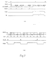
- the micro-computer MPU 96 outputs a signal PIXW indicated in Fig. 7, instruction entry of the signal sent from the comparator 8 into the random access memory 94 via the flip-flop circuit 100.
- the signal PIXW is input to the address counter 95.
- this address counter 95 starts counting in order to count 1216 bits of picture data output from the image sensor 6. This is indicated as AD COUNT in the time chart of Fig. 7(a).
- the address counter 95 Upon completion of counting 1216 bits of picture data, the address counter 95 outputs the reset signal to the flip-flop 100. Thereby an output of flip-flop 100 is inverted and thus data entry to RAM 94 is completed.
- JK-FF J-K flip flops
- JK-FF 91 has the function of detecting that a line is all white, namely has an "all white” line detecting function
- JK-FF 92 has the function of detecting in which blocks, among those obtained by dividing a line into the predetermined blocks, are all white, namely has an "all white” block detecting function.
- JK-FF 91 The signals sent from the comparator 8 are respectively input to the J, K terminals of JK-FF 91 as logic 1 and logic 0 signals. Since logic 1 represents a white signal W and logic 0 a black signal B, when the 1216 bits of picture data are all white signals W, an output of the output terminal Q of JK-FF 91 when the 1216 bits have all been input to the JK-FF 91 is logic 0. In case a black signal B exists, even a single bit, within the 1216 bits, an output of the output terminal Q when 1216 bits have all been input is logic 1.
- the MPU 96 discriminates whether a black signal B exists or not in the 1216 bits, by means of an output sent from the Q terminal of JK-FF 91. According to the result of discrimination, it is judged whether an all white skip signal should be generated or not, as explained later.
- JK-FF 92 operation of JK-FF 92 will be explained.
- one line of 1216 bits is divided into blocks of predetermined number.
- a line is divided into 19 blocks equally and each block is composed of 64 bits.
- the JK-FF 91 sends a detected signal (output from its Q terminal) to the SKIPL terminal of MPU 96 after detecting whether every block is all white signal W or not and the MPU 96 generates the sending signal based on such data.
- JK-FF 92 Operations of JK-FF 92 are generally similar to those of JK-FF 91.
- a signal input to the reset terminal of JK-FF 92 is a signal BLCK which is output every 64 bits from the address counter 95.
- a signal obtained every 1216 bits serves as the reset signal for JK-FF 91.
- a signal which detects whether or not an all white block exists for every 64 bits, namely for each block is input to the shift register 93 and thereafter input to terminals SKGO to SKGn of MPU 96.
- Fig. 7(b) indicates the send signal SEND.
- the time axis is compressed as compared with that in Fig. 7(a).
- the send signal SEND is composed of a signal BLC which indicates in which block among 19 blocks the black signal B exists and the signal PIX which indicates where black signals B exist amongst those blocks (64 bits) judged as including black signals B.
- the signal BLC is composed of a heading dummy signal lasting several milliseconds, followed by an all white indication signal SKIPL which indicates whether one line, 1216 bits, are all "white” or not and signals BLO to BLn which indicate blocks including black signals B.
- the MPU 96 When the signal PIXW which instructs entry to RAM 94 is output from the MPU 96 in order to indicate data entry, the MPU 96 generates the send signal within the time where said dummy signal exists and the signal BLC is output from the MPU 96. At this time, the switch circuit 101 is connected to the terminal SO of MPU 96 in accordance with the signal PIXS.
- the switch circuit 101 When the signal PIX appears following the signal BLC, the switch circuit 101 is connected to the output side of RAM 94 in accordance with the signal PIXS and the signal PIX indicating existence of the black signal B is input to the modulator 10.
- control is carried out as follows by the signal PIXW, signals BL1 to 16, and the switch circuits 98 and 99.
- the MPU 96 discriminates blocks which are not all white blocks depending on the all white block data sent from the shift register 93, outputs the number from the BL1 to BL16 lines and simultaneously the PIXS signal, changes the clocks of address counter 95 to the send clock (DTCK), and moreover changes the data input signal (MODEM IN) of the modulator 10 to the RAM output by means of the switch circuit 97, and reads the picture signal of 64 bits of the block specified by BL1 to BL16 from the RAM output and then inputs it as the send data of the modulator 10. Similar operations are repeated for the number of times of blocks which are not all white blocks.
- the signal TGT in Fig. 7(b) instructs the image sensor 6 to accumulate charges for reading picture data.
- This signal causes the image sensor to discharge at a predetermined period, because if charges were accumulated continuously, the sensor would be charged up to levels indicating black signals B, resulting in discrimination errors for white signals W.
- the clock generator 11 outputs the clock CCDCK (331 kHz in this embodiment) to be supplied to the system of image sensor 6 and the clock DTCK (7.8 kHz in this embodiment), to be supplied to the address counter.
- This clock is supplied to the address counter 95 through the changeover operation of switch circuit 97 depending on the signal PIXS sent from the MPU 96, for picture signal processing.
- the JK-FF 12 is provided for generating the clocks (P A , ⁇ B to be supplied to the CCD used as the image sensor 6.
- the voltage converter 13 converts the logic circuit voltage of 5V to the analog circuit voltage of 13V.
- Fig. 8 (a) is the charge accumulation instruction signal TGT for the image sensor shown in Fig. 4, (b) is the send signal to be sent to the transmission path, (c) is the subscanning instruction signal which instructs start of subscanning to the motor, (d) is a shift line, indicating shifting of the manuscript, (e) indicates image sensor read time, (f) is a time chart indicating changes of threshold level.
- B indicates the subscanning direction.
- Fig. 8 (a), (b) are respectively the same as the signals TGT and SEND in Fig. 7.
- the subscanning instruction signal (c) is generated in synchronization with the signal TGT simultaneously with start of the SEND signal.
- the manuscript is fed a fixed distance b from the point where the subscanning signal (c) is generated as indicated by the shift line in (d) and then stops.
- the read time (e) of the image sensor 6 exists only in the period of signal (a) just before generation of the subscanning instruction signal (c).
- the threshold level for discriminating the white signal W and the black signal B is changed in order to prevent such discrimination error.
- a change of threshold level is shown in Fig. 8(f). Namely, in such a case, it is required to bring the threshold level close to the level of white picture data, since the occupation rate of black picture data per unit area is reduced.
- Fig. 6 The control circuit for this purpose is shown in Fig. 6.
- This Figure indicates the structure of threshold level control circuit 14 in an embodiment of the present invention shown in Fig. 4.
- the counter 141 receives the signal sent from the terminal Q of JK-FF 92 at a clock terminal CK, and it also receives the signal sent from the reset terminal RST of JK-FF 92 at its reset terminal RST. Since JK-FF 92 outputs logic 1 for each all white block from its Q output terminal, the number of blocks which are not all white can be counted by inputting such logic 1 signal, after it is inverted by the invertor, to the counter 141. Signals from counter 141 are input to OR circuits 143, 144 via decoder 142 and from that decoder respectively input to terminals D of the flip-flop circuits 146, 147.
- the flip-flop 145 receives the signal SKIPL at its terminal D, via invertor 148.
- the signal PIXW is input to the clock terminals CK of each of flip-flop circuits 145, 146 and 147.
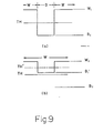
- Such control is effective for controlling the threshold level of the comparator 8 corresponding to the processing time of the SEND signal. This process is explained with reference to Figs. 9(a) and (b).
- the white signal W and the black signal B are discriminated using a specified threshold level TH.
- the threshold level is shifted to TH' from TH through control as shown in Fig. 9(b).
- Such control is performed by the threshold level control circuit shown in Fig. 6.
Landscapes
- Engineering & Computer Science (AREA)
- Multimedia (AREA)
- Signal Processing (AREA)
- Facsimile Scanning Arrangements (AREA)
- Facsimile Image Signal Circuits (AREA)
Claims (2)
Applications Claiming Priority (2)
| Application Number | Priority Date | Filing Date | Title |
|---|---|---|---|
| JP161740/80 | 1980-11-17 | ||
| JP55161740A JPS5784670A (en) | 1980-11-17 | 1980-11-17 | Video signal read-in system |
Publications (3)
| Publication Number | Publication Date |
|---|---|
| EP0064557A1 EP0064557A1 (de) | 1982-11-17 |
| EP0064557A4 EP0064557A4 (de) | 1985-11-07 |
| EP0064557B1 true EP0064557B1 (de) | 1988-09-21 |
Family
ID=15740975
Family Applications (1)
| Application Number | Title | Priority Date | Filing Date |
|---|---|---|---|
| EP81903064A Expired EP0064557B1 (de) | 1980-11-17 | 1981-11-11 | Verfahren zum Lesen eines Bildsignals |
Country Status (5)
| Country | Link |
|---|---|
| US (1) | US4482922A (de) |
| EP (1) | EP0064557B1 (de) |
| JP (1) | JPS5784670A (de) |
| DE (1) | DE3176885D1 (de) |
| WO (1) | WO1982001798A1 (de) |
Families Citing this family (4)
| Publication number | Priority date | Publication date | Assignee | Title |
|---|---|---|---|---|
| AU575788B2 (en) * | 1982-10-08 | 1988-08-11 | Canon Kabushiki Kaisha | Image processing system |
| JPS60230767A (ja) * | 1984-04-28 | 1985-11-16 | Toshiba Corp | 画像信号の二値化方式 |
| EP0220069B1 (de) | 1985-10-18 | 1991-01-09 | Matsushita Graphic Communication Systems, Inc. | Korrektur-/Lesegerät bezogen auf eine vorangegangene Aufzeichnung |
| US4876605A (en) * | 1987-01-12 | 1989-10-24 | Oki Electric Industry Co., Ltd. | Image reading device |
Citations (2)
| Publication number | Priority date | Publication date | Assignee | Title |
|---|---|---|---|---|
| JPS5050810A (de) * | 1973-09-05 | 1975-05-07 | ||
| JPS5341920A (en) * | 1976-09-29 | 1978-04-15 | Ricoh Co Ltd | Telautograph information reading device |
Family Cites Families (10)
| Publication number | Priority date | Publication date | Assignee | Title |
|---|---|---|---|---|
| US3947627A (en) * | 1972-10-30 | 1976-03-30 | Matsushita Electric Industrial Company, Limited | Facsimile system |
| JPS5222494B2 (de) * | 1972-12-15 | 1977-06-17 | ||
| JPS5421051B2 (de) * | 1973-03-30 | 1979-07-27 | ||
| JPS52151513A (en) * | 1976-06-11 | 1977-12-16 | Hitachi Ltd | Binary signal generation device |
| JPS6019708B2 (ja) * | 1977-03-28 | 1985-05-17 | 株式会社リコー | 画信号2値化回路 |
| JPS53146522A (en) * | 1977-05-16 | 1978-12-20 | Ricoh Co Ltd | Telautogram information extracting system |
| FR2425780A1 (fr) * | 1978-05-12 | 1979-12-07 | Cit Alcatel | Convertisseur auto-adaptatif en tout ou rien d'un signal d'analyse d'image |
| FR2437125A1 (fr) * | 1978-09-21 | 1980-04-18 | Cit Alcatel | Dispositif de traitement d'un signal d'analyse d'image |
| JPH0550810A (ja) * | 1991-08-22 | 1993-03-02 | Bridgestone Corp | 空気入りタイヤ |
| JPH05341920A (ja) * | 1992-06-05 | 1993-12-24 | Nec Corp | パラレルディスク装置 |
-
1980
- 1980-11-17 JP JP55161740A patent/JPS5784670A/ja active Granted
-
1981
- 1981-11-11 DE DE8181903064T patent/DE3176885D1/de not_active Expired
- 1981-11-11 US US06/403,495 patent/US4482922A/en not_active Expired - Lifetime
- 1981-11-11 WO PCT/JP1981/000329 patent/WO1982001798A1/ja not_active Ceased
- 1981-11-11 EP EP81903064A patent/EP0064557B1/de not_active Expired
Patent Citations (2)
| Publication number | Priority date | Publication date | Assignee | Title |
|---|---|---|---|---|
| JPS5050810A (de) * | 1973-09-05 | 1975-05-07 | ||
| JPS5341920A (en) * | 1976-09-29 | 1978-04-15 | Ricoh Co Ltd | Telautograph information reading device |
Also Published As
| Publication number | Publication date |
|---|---|
| JPS5784670A (en) | 1982-05-27 |
| EP0064557A1 (de) | 1982-11-17 |
| US4482922A (en) | 1984-11-13 |
| DE3176885D1 (en) | 1988-10-27 |
| WO1982001798A1 (en) | 1982-05-27 |
| EP0064557A4 (de) | 1985-11-07 |
| JPS628064B2 (de) | 1987-02-20 |
Similar Documents
| Publication | Publication Date | Title |
|---|---|---|
| US3919464A (en) | Facsimile transmission system | |
| US4301479A (en) | Signal processing system of facsimile | |
| GB2172767A (en) | Compression and expansion of image signals | |
| US3947627A (en) | Facsimile system | |
| EP0139174B1 (de) | Gerät für die Wiedergabe von Bildern | |
| US4413285A (en) | Facsimile apparatus | |
| EP0064557B1 (de) | Verfahren zum Lesen eines Bildsignals | |
| EP0881818B1 (de) | Korrektur des Vertikalabgleichs | |
| US4413287A (en) | White line skipping | |
| GB2172465A (en) | Compression & expansion of image signals | |
| US4470073A (en) | Facsimile transmitter | |
| JPS6247026B2 (de) | ||
| US5999275A (en) | Image reader | |
| US4338637A (en) | Variable scanning device | |
| US4356516A (en) | Transmitter for facsimile | |
| US6160630A (en) | Image reading apparatus | |
| US4270147A (en) | Apparatus for limiting facsimile transmission durations | |
| JPS5753178A (en) | Facsimile device | |
| JPS6338911B2 (de) | ||
| EP0712233A1 (de) | Bildaufzeichnungsvorrichtung | |
| KR960012537B1 (ko) | 화상크기 가변전송기능을 갖는 팩시밀리 장치 및 방법 | |
| JPS58104568A (ja) | 細線読取り方式 | |
| JP2001290226A (ja) | 画像読取装置 | |
| JPH0131829B2 (de) | ||
| JPH0573307B2 (de) |
Legal Events
| Date | Code | Title | Description |
|---|---|---|---|
| PUAI | Public reference made under article 153(3) epc to a published international application that has entered the european phase |
Free format text: ORIGINAL CODE: 0009012 |
|
| 17P | Request for examination filed |
Effective date: 19820714 |
|
| AK | Designated contracting states |
Designated state(s): DE FR GB |
|
| 17Q | First examination report despatched |
Effective date: 19870325 |
|
| GRAA | (expected) grant |
Free format text: ORIGINAL CODE: 0009210 |
|
| AK | Designated contracting states |
Kind code of ref document: B1 Designated state(s): DE FR GB |
|
| REF | Corresponds to: |
Ref document number: 3176885 Country of ref document: DE Date of ref document: 19881027 |
|
| ET | Fr: translation filed | ||
| PLBE | No opposition filed within time limit |
Free format text: ORIGINAL CODE: 0009261 |
|
| STAA | Information on the status of an ep patent application or granted ep patent |
Free format text: STATUS: NO OPPOSITION FILED WITHIN TIME LIMIT |
|
| 26N | No opposition filed | ||
| REG | Reference to a national code |
Ref country code: FR Ref legal event code: TP |
|
| REG | Reference to a national code |
Ref country code: GB Ref legal event code: 732E |
|
| PGFP | Annual fee paid to national office [announced via postgrant information from national office to epo] |
Ref country code: GB Payment date: 19961104 Year of fee payment: 16 |
|
| PGFP | Annual fee paid to national office [announced via postgrant information from national office to epo] |
Ref country code: FR Payment date: 19961111 Year of fee payment: 16 |
|
| PGFP | Annual fee paid to national office [announced via postgrant information from national office to epo] |
Ref country code: DE Payment date: 19961115 Year of fee payment: 16 |
|
| PG25 | Lapsed in a contracting state [announced via postgrant information from national office to epo] |
Ref country code: GB Free format text: LAPSE BECAUSE OF NON-PAYMENT OF DUE FEES Effective date: 19971111 |
|
| PG25 | Lapsed in a contracting state [announced via postgrant information from national office to epo] |
Ref country code: FR Free format text: THE PATENT HAS BEEN ANNULLED BY A DECISION OF A NATIONAL AUTHORITY Effective date: 19971130 |
|
| GBPC | Gb: european patent ceased through non-payment of renewal fee |
Effective date: 19971111 |
|
| PG25 | Lapsed in a contracting state [announced via postgrant information from national office to epo] |
Ref country code: DE Free format text: LAPSE BECAUSE OF NON-PAYMENT OF DUE FEES Effective date: 19980801 |
|
| REG | Reference to a national code |
Ref country code: FR Ref legal event code: ST |