EP0064566B1 - Dispositif pour détecter des objets métalliques dans des récolteuses-hacheuses - Google Patents
Dispositif pour détecter des objets métalliques dans des récolteuses-hacheuses Download PDFInfo
- Publication number
- EP0064566B1 EP0064566B1 EP81103543A EP81103543A EP0064566B1 EP 0064566 B1 EP0064566 B1 EP 0064566B1 EP 81103543 A EP81103543 A EP 81103543A EP 81103543 A EP81103543 A EP 81103543A EP 0064566 B1 EP0064566 B1 EP 0064566B1
- Authority
- EP
- European Patent Office
- Prior art keywords
- bearing
- drive
- ball
- axle
- feed roller
- Prior art date
- Legal status (The legal status is an assumption and is not a legal conclusion. Google has not performed a legal analysis and makes no representation as to the accuracy of the status listed.)
- Expired
Links
- 241001124569 Lycaenidae Species 0.000 title description 3
- 239000002184 metal Substances 0.000 title 1
- 239000000463 material Substances 0.000 claims abstract description 7
- CWYNVVGOOAEACU-UHFFFAOYSA-N Fe2+ Chemical compound [Fe+2] CWYNVVGOOAEACU-UHFFFAOYSA-N 0.000 claims abstract description 5
- 230000000717 retained effect Effects 0.000 claims abstract 3
- 239000004459 forage Substances 0.000 description 6
- XEEYBQQBJWHFJM-UHFFFAOYSA-N Iron Chemical compound [Fe] XEEYBQQBJWHFJM-UHFFFAOYSA-N 0.000 description 4
- 230000005489 elastic deformation Effects 0.000 description 3
- 230000006698 induction Effects 0.000 description 2
- 229910052742 iron Inorganic materials 0.000 description 2
- 240000008042 Zea mays Species 0.000 description 1
- 235000016383 Zea mays subsp huehuetenangensis Nutrition 0.000 description 1
- 235000002017 Zea mays subsp mays Nutrition 0.000 description 1
- 230000006978 adaptation Effects 0.000 description 1
- 230000000694 effects Effects 0.000 description 1
- 230000005294 ferromagnetic effect Effects 0.000 description 1
- 230000010006 flight Effects 0.000 description 1
- 238000003306 harvesting Methods 0.000 description 1
- 230000005291 magnetic effect Effects 0.000 description 1
- 235000009973 maize Nutrition 0.000 description 1
- 210000000056 organ Anatomy 0.000 description 1
- 230000001960 triggered effect Effects 0.000 description 1
Images
Classifications
-
- G—PHYSICS
- G01—MEASURING; TESTING
- G01V—GEOPHYSICS; GRAVITATIONAL MEASUREMENTS; DETECTING MASSES OR OBJECTS; TAGS
- G01V3/00—Electric or magnetic prospecting or detecting; Measuring magnetic field characteristics of the earth, e.g. declination, deviation
- G01V3/08—Electric or magnetic prospecting or detecting; Measuring magnetic field characteristics of the earth, e.g. declination, deviation operating with magnetic or electric fields produced or modified by objects or geological structures or by detecting devices
- G01V3/10—Electric or magnetic prospecting or detecting; Measuring magnetic field characteristics of the earth, e.g. declination, deviation operating with magnetic or electric fields produced or modified by objects or geological structures or by detecting devices using induction coils
- G01V3/104—Electric or magnetic prospecting or detecting; Measuring magnetic field characteristics of the earth, e.g. declination, deviation operating with magnetic or electric fields produced or modified by objects or geological structures or by detecting devices using induction coils using several coupled or uncoupled coils
-
- A—HUMAN NECESSITIES
- A01—AGRICULTURE; FORESTRY; ANIMAL HUSBANDRY; HUNTING; TRAPPING; FISHING
- A01D—HARVESTING; MOWING
- A01D75/00—Accessories for harvesters or mowers
- A01D75/18—Safety devices for parts of the machines
- A01D75/187—Removing foreign objects
-
- A—HUMAN NECESSITIES
- A01—AGRICULTURE; FORESTRY; ANIMAL HUSBANDRY; HUNTING; TRAPPING; FISHING
- A01F—PROCESSING OF HARVESTED PRODUCE; HAY OR STRAW PRESSES; DEVICES FOR STORING AGRICULTURAL OR HORTICULTURAL PRODUCE
- A01F29/00—Cutting apparatus specially adapted for cutting hay, straw or the like
- A01F29/09—Details
- A01F29/16—Safety devices, e.g. emergency brake arrangements
Definitions
- the invention relates to a device for recognizing ferrous material in forage harvesters with the features of the preamble of the main claim.
- a device for recognizing ferrous material in forage harvesters has become known, for example, from DE-A-2552805.
- the forage harvester itself is constructed in a conventional manner.
- the chopping elements consisting of a revolving knife drum and a shear bar, are preceded by a feed device, which consists of two lower, fixedly arranged in the machine frame and two upper, for the purpose of adaptation to different thickness crop mats pivotally mounted upper feed rollers. These paired lower and upper feed rollers have the task of compacting the harvested crop and feeding it to the chopping organs.
- a signal generating device is installed in the front, lower feed roller.
- the known signal generator device comprises a signal generator for a constant signal and a magnetic coil device which is able to interrupt the signal generator if undesired objects get into the area of the feed rollers.
- the signal generator device is supported on both sides on an axis. One end of this axis is supported in the drive shaft stub for the feed roller.
- the drive shaft stub is supported by a ball bearing on one side of the machine frame.
- the proposed mounting of the feed roller has the disadvantage that the position of the axis of the signal generator device changes relatively strongly when loads occur.
- a deflection of the drive shaft stub, supported by the large bearing distances, causes a large deflection of this axis.
- a one-sided deflection of the feed roller does not have an impact on the position of the axis. In practice, however, it has been found that even small deviations in the position of the signal generating device with respect to both rotating and stationary machine elements trigger unwanted interference signals.
- the present invention is based on the object of eliminating unwanted interference signals in a device of the type in question by means of a signal generator device which is practically non-reactive from external influences.
- the invention solves this problem by the measures specified in the characterizing part of the main claim.
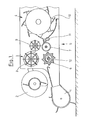
- Fig. 1 the basic structure of a forage harvester is shown schematically in longitudinal section. It is irrelevant to the invention whether it is an attached or self-propelled chopper.
- a screw 2 with opposite screw flights brings the crop together towards the center and transfers it to a feed device, from where it is passed on to the chopping elements 4.
- other attachments such as find a device for harvesting maize in line.
- the feed device 3 is formed from lower, drivable and fixedly mounted in the machine frame 5 feed rollers 6 and 7 and upper, with respect to the machine frame 5 pivotally mounted feed rollers 8 and 9. These feed rolls will be pulled by tension springs, not shown, in the direction of the lower rollers 6 and 7 and have the task of compressing the crop in addition to conveying in the direction of the chopping elements 4 into a mat.
- the chopping elements 4 consist in a known manner of a rotating knife drum 10 which interacts with a fixed shearbar 11.
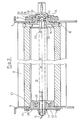
- a signal generator device 12 is preferably fixed in position in the front, lower feed roller 6 with respect to the machine frame 5. In order to ensure a trouble-free function of the signal generator device, external influences which would lead to a change in position and / or shape of the signal generator device must be kept away from the latter. In order to achieve this goal, the signal generator device according to FIG. 2 is mounted as follows.
- the signal generator device 12 consists of a plurality of permanent magnets, to which a number of induction coils are assigned.
- the connections of these induction coils, which are connected to a signal processing device, not shown, are designated by the reference number 13.
- the reference number 13 instead of the structure of the signal generator device described, it can also be configured in any desired way, since it is only important for its intended function to detect foreign objects carried along.
- the signal generator device 12 is firmly connected on the one hand to an axle stub 14 on the left in the drawing and on the other hand to an axle stub 15 on the right in the drawing. It is important that the signal generator device 12 is arranged in a fixed position with respect to the machine frame 5.
- the front, lower feed roller 6 is designed as a hollow roller. In order to ensure the function of the device for recognizing ferrous material, it is made of non-magnetizable material, in the exemplary embodiment shown of plastic.
- the end of the feed roller 6 on the right in the drawing is connected in a rotationally fixed manner via a plurality of radially directed fastening screws 16 distributed around the circumference of the roller to an approximately bell-shaped drive shaft stub 17.
- the free end of the drive shaft stub 17 is connected to a drive shaft, not shown, in a rotationally fixed connection.
- the drive shaft stub 17 has a bearing collar 18 which carries a pendulum ball bearing 19.
- the fixed outer ring 20 of the self-aligning ball bearing 19 is held by a two-part bearing housing 21.
- the bearing housing 21 is fixed to the machine frame 5 by means of a plurality of fastening screws 22 distributed over the circumference.
- the stub axle 15 has a bearing pin 23 which is mounted in a recess 25 of the drive shaft stub 17 with the aid of a further ball bearing 24.
- the ball bearing 24 and the self-aligning ball bearing 19 are arranged such that they have a common center point 26.
- the pendulum ball bearing 19 and its position relative to the further ball bearing 24 can compensate for changes in shape of the machine frame 5 or changes in shape of the feed roller 6 and the drive shaft stub 17 such that no change in shape or position of the axle stub 15 and thus the signal generator device 12 is caused . In this way, unwanted disturbances can be reliably eliminated.
- the left end of the feed roller 6 in the drawing is supported on a ring 27.
- a bearing flange 28 firmly connected to the machine frame 5 carries a self-aligning ball bearing 29, the outer ring of which is inserted in the ring 27 in a rotationally fixed manner.
- the end of the feed roller 6 on the left in the drawing is supported directly on the machine frame 5 via the bearing flange 28, without a connection to the stub shaft 14. Any changes in shape and position of the machine frame 5 or the left end of the feed roller 6 therefore have no influence on the position of the axle stub 14. Since the axle stub 14 must be arranged in a fixed position with respect to the machine frame 5, a safeguard against rotation of the axle stub 14 is provided necessary.
- the anti-rotation device consists of a relatively thin-walled web 30, which is on the one hand in a rotationally fixed connection with the stub shaft 14 and on the other hand is fixed to the machine frame 5 by means of fastening screws 31.
- the web 30 only fulfills the task of securing the stub axle 14 in the position shown. Due to its elastic design, it is able to absorb deformations caused by external influences without any change in the position of the stub axle 14.
- the above-described mounting of the stub axles 14 and 15 ensures that the signal generator device 12 is arranged without any external influences. In this way, as the practical use of the device designed according to the invention for detecting iron-containing material proves, undesirable sources of interference can be eliminated.
Landscapes
- Life Sciences & Earth Sciences (AREA)
- Physics & Mathematics (AREA)
- Engineering & Computer Science (AREA)
- Environmental Sciences (AREA)
- Remote Sensing (AREA)
- Geology (AREA)
- Environmental & Geological Engineering (AREA)
- General Life Sciences & Earth Sciences (AREA)
- General Physics & Mathematics (AREA)
- Geophysics (AREA)
- Electromagnetism (AREA)
- Geophysics And Detection Of Objects (AREA)
- Threshing Machine Elements (AREA)
- Harvester Elements (AREA)
- Agricultural Machines (AREA)
Claims (5)
Priority Applications (3)
| Application Number | Priority Date | Filing Date | Title |
|---|---|---|---|
| AT81103543T ATE18489T1 (de) | 1981-05-09 | 1981-05-09 | Vorrichtung zum erkennen von eisenhaltigem material in feldhaeckslern. |
| EP81103543A EP0064566B1 (fr) | 1981-05-09 | 1981-05-09 | Dispositif pour détecter des objets métalliques dans des récolteuses-hacheuses |
| DE8181103543T DE3174036D1 (en) | 1981-05-09 | 1981-05-09 | Metal detector apparatus in crop harvesters |
Applications Claiming Priority (1)
| Application Number | Priority Date | Filing Date | Title |
|---|---|---|---|
| EP81103543A EP0064566B1 (fr) | 1981-05-09 | 1981-05-09 | Dispositif pour détecter des objets métalliques dans des récolteuses-hacheuses |
Publications (2)
| Publication Number | Publication Date |
|---|---|
| EP0064566A1 EP0064566A1 (fr) | 1982-11-17 |
| EP0064566B1 true EP0064566B1 (fr) | 1986-03-12 |
Family
ID=8187705
Family Applications (1)
| Application Number | Title | Priority Date | Filing Date |
|---|---|---|---|
| EP81103543A Expired EP0064566B1 (fr) | 1981-05-09 | 1981-05-09 | Dispositif pour détecter des objets métalliques dans des récolteuses-hacheuses |
Country Status (3)
| Country | Link |
|---|---|
| EP (1) | EP0064566B1 (fr) |
| AT (1) | ATE18489T1 (fr) |
| DE (1) | DE3174036D1 (fr) |
Families Citing this family (5)
| Publication number | Priority date | Publication date | Assignee | Title |
|---|---|---|---|---|
| DE19742060B4 (de) * | 1997-09-24 | 2005-02-03 | Claas Selbstfahrende Erntemaschinen Gmbh | Fremdkörperrückführvorrichtung an Erntemaschinen o. dgl. |
| DE102008054488B4 (de) * | 2008-12-10 | 2020-10-22 | Deere & Company | Einrichtung zum Nachweis eines in eine Erntemaschine eingedrungenen Fremdkörpers |
| DE102012201906B4 (de) * | 2012-02-09 | 2017-03-30 | Deere & Company | Einzugszusammenbau für einen Feldhäcksler |
| CN109969809A (zh) * | 2017-12-27 | 2019-07-05 | 中车大同电力机车有限公司 | 一种取料滚筒安装传动结构 |
| DE102018003555B4 (de) * | 2018-05-03 | 2020-03-12 | Maschinenfabrik Bernard Krone GmbH & Co. KG | Einzugswalze für eine Erntemaschine |
Family Cites Families (3)
| Publication number | Priority date | Publication date | Assignee | Title |
|---|---|---|---|---|
| US3972156A (en) * | 1975-02-24 | 1976-08-03 | Sperry Rand Corporation | Speed-independent static magnetic field metal detector |
| GB2013072B (en) * | 1977-12-02 | 1982-05-12 | Sperry Rand Nv | Crop harvesting machines |
| DE2940201A1 (de) * | 1979-10-04 | 1981-05-07 | Claas Ohg, 4834 Harsewinkel | Feldhaecksler mit metalldetektor |
-
1981
- 1981-05-09 EP EP81103543A patent/EP0064566B1/fr not_active Expired
- 1981-05-09 DE DE8181103543T patent/DE3174036D1/de not_active Expired
- 1981-05-09 AT AT81103543T patent/ATE18489T1/de active
Also Published As
| Publication number | Publication date |
|---|---|
| ATE18489T1 (de) | 1986-03-15 |
| EP0064566A1 (fr) | 1982-11-17 |
| DE3174036D1 (en) | 1986-04-17 |
Similar Documents
| Publication | Publication Date | Title |
|---|---|---|
| DE2265809C2 (de) | Erntemaschine mit einem Erkennungsgerät für metallische Fremdkörper | |
| DE2552805C2 (de) | Erntemaschine, insbesondere Feldhäcksler | |
| EP1380204B1 (fr) | Méthode et dispositif pour le changement automatique de position de l'élément de post-accélération dans une moissonneuse agricole | |
| DE2940201A1 (de) | Feldhaecksler mit metalldetektor | |
| EP3449718B1 (fr) | Dispositif de pesage et appareil de récuperation de cueillette | |
| EP0803458B1 (fr) | Dispositif pour contrôler la position d'une bande en cours de défilement transversalement à la direction de défilement | |
| DE3407333C2 (fr) | ||
| EP1790206A1 (fr) | Ramasseur pour récolteuse | |
| DE102012000301A1 (de) | Mähmaschine | |
| EP0064566B1 (fr) | Dispositif pour détecter des objets métalliques dans des récolteuses-hacheuses | |
| DE19912407A1 (de) | Förderer mit Metalldetektionseinrichtung | |
| EP1741330B1 (fr) | Dispositif de ramassage pour ramasser des produits agricoles sur le sol | |
| EP3706546B1 (fr) | Ramasseuse pourvue d'un détecteur de métaux | |
| EP4147562B1 (fr) | Procédé, appareil de commande et système de commande pour faire fonctionner une moissonneuse agricole ainsi que moissonneuse agricole | |
| EP0153621B1 (fr) | Hacheuse à tambour avec une broyeuse secondaire | |
| EP1163838B1 (fr) | Machine de récolte, notamment presse à balles rondes | |
| EP1523876B1 (fr) | Transporteur avec dispositif de détection de métal | |
| BE1026594B1 (de) | Anordnung zur Einstellung der Position der Gegenschneide eines Feldhäckslers | |
| DE102005008448A1 (de) | Lagerung eines Gutförder-und/oder Gutbearbeitungselements für eine Erntemaschine | |
| DE10332395A1 (de) | Erntemaschine | |
| EP0014854A1 (fr) | Dispositif de ramassage pour une hacheuse récolteuse | |
| EP0832551B1 (fr) | Ensemble d'alimentation | |
| BE1021657B1 (de) | Einzugszusammenbau für einen feldhäcksler | |
| DE3124187C2 (de) | Fahrbares Gerät mit einer Schnittgutaufnahme-Vorrichtung zur Behandlung von geschnittenem, schwadförmig geordnetem Pflanzengut | |
| DE8113781U1 (de) | Vorrichtung zum Erkennen von eisenhaltigem Material in Feldhäckslern |
Legal Events
| Date | Code | Title | Description |
|---|---|---|---|
| PUAI | Public reference made under article 153(3) epc to a published international application that has entered the european phase |
Free format text: ORIGINAL CODE: 0009012 |
|
| AK | Designated contracting states |
Designated state(s): AT BE CH DE FR GB NL |
|
| 17P | Request for examination filed |
Effective date: 19821208 |
|
| GRAA | (expected) grant |
Free format text: ORIGINAL CODE: 0009210 |
|
| AK | Designated contracting states |
Kind code of ref document: B1 Designated state(s): AT BE CH DE FR GB LI NL |
|
| REF | Corresponds to: |
Ref document number: 18489 Country of ref document: AT Date of ref document: 19860315 Kind code of ref document: T |
|
| REF | Corresponds to: |
Ref document number: 3174036 Country of ref document: DE Date of ref document: 19860417 |
|
| RAP2 | Party data changed (patent owner data changed or rights of a patent transferred) |
Owner name: KLOECKNER-HUMBOLDT-DEUTZ AG ZWEIGNIEDERLASSUNG FAH |
|
| PGFP | Annual fee paid to national office [announced via postgrant information from national office to epo] |
Ref country code: AT Payment date: 19860509 Year of fee payment: 6 |
|
| ET | Fr: translation filed | ||
| PGFP | Annual fee paid to national office [announced via postgrant information from national office to epo] |
Ref country code: NL Payment date: 19860531 Year of fee payment: 6 |
|
| NLXE | Nl: other communications concerning ep-patents (part 3 heading xe) |
Free format text: IN PAT.BUL.11/86,PAGES 1292 AND 1351 SHOULD BE MODIFIED INTO:KLOECKNER-HUMBOLDT-DEUTZ AG ZWEIGNIEDERLASSUNG FAHR |
|
| BECN | Be: change of holder's name |
Effective date: 19860312 |
|
| PLBE | No opposition filed within time limit |
Free format text: ORIGINAL CODE: 0009261 |
|
| STAA | Information on the status of an ep patent application or granted ep patent |
Free format text: STATUS: NO OPPOSITION FILED WITHIN TIME LIMIT |
|
| 26N | No opposition filed | ||
| PG25 | Lapsed in a contracting state [announced via postgrant information from national office to epo] |
Ref country code: AT Effective date: 19870509 |
|
| PG25 | Lapsed in a contracting state [announced via postgrant information from national office to epo] |
Ref country code: LI Effective date: 19870531 Ref country code: CH Effective date: 19870531 |
|
| BERE | Be: lapsed |
Owner name: KLOCKNER-HUMBOLDT-DEUTZ A.G. ZWEIGNIEDERLASSUNG F Effective date: 19870531 |
|
| PG25 | Lapsed in a contracting state [announced via postgrant information from national office to epo] |
Ref country code: NL Effective date: 19871201 |
|
| NLV4 | Nl: lapsed or anulled due to non-payment of the annual fee | ||
| PG25 | Lapsed in a contracting state [announced via postgrant information from national office to epo] |
Ref country code: FR Free format text: LAPSE BECAUSE OF NON-PAYMENT OF DUE FEES Effective date: 19880129 |
|
| REG | Reference to a national code |
Ref country code: CH Ref legal event code: PL |
|
| PG25 | Lapsed in a contracting state [announced via postgrant information from national office to epo] |
Ref country code: DE Effective date: 19880202 |
|
| GBPC | Gb: european patent ceased through non-payment of renewal fee | ||
| REG | Reference to a national code |
Ref country code: FR Ref legal event code: ST |
|
| PG25 | Lapsed in a contracting state [announced via postgrant information from national office to epo] |
Ref country code: GB Free format text: LAPSE BECAUSE OF NON-PAYMENT OF DUE FEES Effective date: 19881121 |
|
| PG25 | Lapsed in a contracting state [announced via postgrant information from national office to epo] |
Ref country code: BE Effective date: 19890531 |