EP0064757A2 - Farbfernsehempfänger - Google Patents
Farbfernsehempfänger Download PDFInfo
- Publication number
- EP0064757A2 EP0064757A2 EP82104042A EP82104042A EP0064757A2 EP 0064757 A2 EP0064757 A2 EP 0064757A2 EP 82104042 A EP82104042 A EP 82104042A EP 82104042 A EP82104042 A EP 82104042A EP 0064757 A2 EP0064757 A2 EP 0064757A2
- Authority
- EP
- European Patent Office
- Prior art keywords
- cathode
- heater
- cathodes
- television receiver
- color
- Prior art date
- Legal status (The legal status is an assumption and is not a legal conclusion. Google has not performed a legal analysis and makes no representation as to the accuracy of the status listed.)
- Withdrawn
Links
Images


Classifications
-
- H—ELECTRICITY
- H04—ELECTRIC COMMUNICATION TECHNIQUE
- H04N—PICTORIAL COMMUNICATION, e.g. TELEVISION
- H04N9/00—Details of colour television systems
- H04N9/64—Circuits for processing colour signals
- H04N9/72—Circuits for processing colour signals for reinsertion of DC and slowly varying components of colour signals
-
- H—ELECTRICITY
- H04—ELECTRIC COMMUNICATION TECHNIQUE
- H04N—PICTORIAL COMMUNICATION, e.g. TELEVISION
- H04N9/00—Details of colour television systems
- H04N9/64—Circuits for processing colour signals
- H04N9/73—Colour balance circuits, e.g. white balance circuits or colour temperature control
Definitions
- the present invention relates to a color television receiver having an automatic cathode cutoff-voltage adjusting circuit for a color picture tube.
- Color television receivers demodulate received video signals into video signals of three primary colors, rea, green, and blue and supply the R, G, and B video signals respectively to the cathodes of a color picture tube to control electron beams from the cathodes which bombard phosphors of different colors on a fluorescent screen to enable the phosphors to emit proper amounts of red, green, and blue light, so that a colored picture image will be reproduced which has been transmitted from a transmitting station.
- a desired shade of color, including white can thus be reproduced by additive color mixture of the three primary colors, red, green, and blue.
- the image which should look white is tinted and all other colors on the screen tecome diferent from those which should appear on the screen if the three primary colors are mixed at a ratio which is different from that for forming white. Under these conditions, the quality of a reproduced color image is degraded.
- Another object of the present invention is to provide a color television receiver having a circuit for applying positive biasing voltages to heaters for the cathodes of a color picture tube during an interval in which a reference voltage signal is added to a luminarce signal.
- a color television receiver includes a color picture tube having three electron guns including cathodes and heaters therefor, respectively, and an automatic cutoff adjusting circuit for adding a reference voltage signal substantially at a black level to a luminance signal during an interval beginning substantially at the end of a vertical deflection blanking period, and for detecting cathode currents during said interval to control cathode voltages for keeping the cathode currents at a predetermined level by way of feedback of voltage proportional to the cathode currents.
- the color television receiver also includes a circuit for applying a positive biasing voltage to each of the heaters during said interval to reduce a potential difference between the heater and corresponding one of the heaters to thereby lower a leakage current flowing between the cathode and the heater.
- Fig. 1 shows cathode-voltage vs. cathode-current characteristics curves for the electron guns in a color picture tube.
- the curves a, b, and c show characteristics, respectively, of the red, green, and blue electron guns.
- the cathode voltages at which the cathode currents fall tc zero, that is, cathode cutoff voltages, vary from one electron gun to another mainly because of irregurality in manufacture.
- the cathode cutoff voltages also changes wit.h time while the electron guns are in use. Under these conditions, the ratio at which the three primary colors are mixed together is changed and the mixed resultant color differs from what should be formed.
- Fig. 2 illustrates such an automatic cutoff adjusting circuit as will be seen from the aforementioned publication.
- a luminance signal supplied to an input terminal 1 is delivered via a reference voltage adder 2 to video amplifiers 3 R , 3 G , 3 B for three colors in which color difference signals are added to the luminance signal to produce video signals.
- the video signals are fed via cathode current detectors 4 R , 4 G , 4 B to cathodes 6 R' 6 G , 6 B , respectively, of electron guns in a color picture tube 5.
- the cathodes 6 R , 6 G , 6 B are heated respectively by heaters 7.
- a pulse signal which is applied to another input terminal 8 is in synchronism with a period in which the reference voltage signal is supplied.
- the pulse signal is delivered to the reference voltage adder 2 and gates 9 R , 9 G' 9 B for the three colors.
- Designated at 10 R , 10 G , 10 B are cathode voltage controllers.
- the reference voltage signal is added to the luminance signal by the reference voltage adder 2 in response to the pulse signal supplied from the input terminal 8 during an interval beginning substantially at the end of a vertical blanking period.
- the luminance signal with the reference voltage signal thus added is converted by the video amplifiers 3 R , 3 G1 3 B into video signals, which are applied through the cathode current detectors 4 R , 4 G , 4 B , respectively, to the cathodes 6 R , 6 G , 6 B .
- the cathode current detectors 4 R , 4 G , 4 B serve to detect voltages proportional to cathode currents.
- the detected voltages are allowed by the gates 9 R' 9 G' 9 B to pass therethrough during the period in which the reference voltage signal is applied in response to the pulse signal delivered from the input terminal 8.
- the voltages which have passed through the gates are fed back to the cathode voltage controllers 10 R , 10 G , 10 B as signals for d-c level control.
- the cathode voltage controllers 10 R , 10 G , 10 B hold the voltages thus fed back and control the cathode voltages to bring the cathode currents to predetermined levels (normally about 10 P A) for automatic cathode cutoff-voltage adjustment.
- Fig. 3 is illustrative of a cathode voltage waveform of one of the video signals to which the reference voltage signal is added.
- Designated at T 1 is the vertical blanking period, and T 2 the period in which the reference voltage signal is supplied, the period T 2 being formed immediately after the vertical blanking period T 1 and during two horizontal deflection periods.
- the waveform includes a vertical retrace pulse 11, horizontal retrace pulses 12, and a video signal 13.
- the pulses have a peak value of 200 V
- the reference voltage signal has a peak value of 160 V
- the video signal has a peak value of 90 V.
- Fig. 4 shows a cathode current detector and a heater circuit.
- a video signal from the video amplifier 3 R is supplied through a transistor 14 to the cathode 6 R .
- the cathode current detector 4 R includes a load resistor 15 for supplying a voltage to the gate 9 R , and the transistor 14.
- the heater 7 is supplied with a current from a heater transformer 16.
- the color picture tube 5, which comprises a cathode-ray tube, requires that the cathode votlage be larger than a heater biasing voltage, and hence the heater 7 has one terminal grounded.
- a voltage of about 160 V (according to the above example) is applied across the cathode 6 R and the heater 7.
- a leakage current I HK of from several microamperes to several of tens of microamperes will flow from the cathode 6 R to the heater 7 when the voltage is applied thereacross.
- the leakage current I HK varies with time and from one gun to another.
- a relationship between a cathode current I K' the leakage current I HK' and a current I KO flowing through the cathode current detector 4 R can be expressed by the following equation:
- the cathode current I K which should be controlled is increased by an amount equal to the leakage current I HK .
- the current I KO is normally about 10 ⁇ A, which is approximately the same as the leakage current I HK that ranges from several microamperes to several of tens of microamperes.
- the cathode current I K undegoes an increase equal to the leakage current I HK , a condition which shifts the color of the image on the fluorescent screen toward the red. Therefore, no proper color image can be produced.
- the leakage current I HK varying with time, the color of the image is shifted to different hues as the leakage current I HK changes.
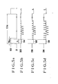
- Figs. 5a through 5d show the waveforms of signals generated in a color television receiver according to the present invention.
- the waveform of Fig. 5a indicates a heater biasing voltage applied to the heater, the waveform of F ig. 5b a cathode voltage for the red gun, the waveform of Fig. 5c a cathode voltage for the green gun, and the waveform of fig. 5d a cathode voltage for the blue gun.
- the heater biasing voltage is applied as a pulse of about 160 V for an interval (150 P s) which includes the period T 2 in which the reference voltage signal is applied, and no heater biasing voltage is applied in the rest of the period of 16.7 ms, which is a vertical deflection period. As shown in fig.
- the cathode cutoff voltages for the red, green, and blue electron guns differ from each other.
- the ratio between the maximum and minimum cutoff voltages is known as a cutoff ratio, which serves as one of the specifications of color picture tubes and may be 1.35 at maximum.
- the cathode cutoff voltage for the red gun is 184 V, which. is the largest
- the cathode cutoff voltage for the blue gun is 136 V, which is the smallest.
- the voltages across the cathodes and heaters of the red, green, and blue electron guns are 24 V, 0 V, and -24 V, respectively, which are much smaller than those in the conventional color television receivers.
- the leakage current I HK is substantially eliminated, and no color shifting appers on the color images.
- the heater biasing voltage is of a relatively small duty cycle as shown in Fig. 5a, its d-c component is substantially nil.
- the d-c component of the cathode voltage is applied positively at all times with respect to the heater, so that the characteristics of the color picture tube will not be affected adversely.
- the heater biasing voltage needs to be at a positive level (about 160 V, for example) during the period T 2 .
- the interval in which the heater biasing voltage is applied should be longer than the period T 2 by a margin of 10 p s at the leading and trailing edges thereof for increased reliability in circuit operation.
- the pulse width of the heater biasing voltage is about 150 P s as shown in Fig. 5a.
- the pulse width margin at the leading edge may be longer than the trailing edge margin.
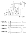
- Fig. 6 shows a circuit for effecting the above operation in accordance with an embodiment of the present invention. Identical parts in Fig. 6 are denoted by idential reference characters in Fig. 4.
- the circuit which is generally designated by reference numeral 20, serves as a heater biasing voltage generator.
- a vertical retrace pulse 22 is applied to an input terminal 21, the pulse 22 is delivered to an integrator comprising a resistor 23 and a capacitor 24.
- An integrated output from the integrator is applied to the base of a transistor 25.
- the signal applied to the transistor base is amplified by the transistor 25 and an amplified signal appears at the collector of the transistor 25 to which a load resistor 26 is connected.
- a pulse peak detector circuit comprises a capacitor 27, a resistor 28, a transistor 29 having a base connected by the capacitor 27 to the collector of the transistor 25 and an emitter connected by the resistor 28 to the base of the transistor 29, and a load resistor 30 connected to the collector of the transistor 29.
- the collector of the transistor 29 is coupled to one terminal of the heater 7 for applying a positive heater biasing voltage that has been developed across the load resistor 30 to the heater 7.
- the heater biasing voltage thus applied is in the form of a pulse with its timing and peak value properly controlled.
- Figs. 7a to 7d are timing charts for the waveforms of various signals.
- the vertical retrace pulse 22 applied to the input terminal 21 has a waveform as shown in Fig. 7a.
- the voltage imposed on the base of the transistor 25 has a waveform as shown in Fig. 7b.
- a waveform as shown in Fig. 7c is of the voltage at the collector of the transistor 25.
- the voltage at the collector of the transistor 29, that is, the heater biasing voltage has a waveform as shown in Fig. 7d.
- the heater biasing voltage generator as shown in Fig. 6 is for illustration only and various modifications thereof may be conceivable.
- a positive voltage is applied to each of the heaters in electron guns of a color picture tube during an interval in which a cathode current is detected by an automatic cutoff adjusting circuit, so that the potential difference between each cathode and corresponding one of the heaters can be reduced to lower a leakage current flowing from the cathode to the heater. Therefore, images which are properly colored can be produced at all times on the fluorescent screen of the color picture tube.
Landscapes
- Engineering & Computer Science (AREA)
- Multimedia (AREA)
- Signal Processing (AREA)
- Processing Of Color Television Signals (AREA)
- Video Image Reproduction Devices For Color Tv Systems (AREA)
Applications Claiming Priority (2)
| Application Number | Priority Date | Filing Date | Title |
|---|---|---|---|
| JP70718/81 | 1981-05-13 | ||
| JP56070718A JPS57186887A (en) | 1981-05-13 | 1981-05-13 | Color television set |
Publications (2)
| Publication Number | Publication Date |
|---|---|
| EP0064757A2 true EP0064757A2 (de) | 1982-11-17 |
| EP0064757A3 EP0064757A3 (de) | 1984-06-06 |
Family
ID=13439618
Family Applications (1)
| Application Number | Title | Priority Date | Filing Date |
|---|---|---|---|
| EP82104042A Withdrawn EP0064757A3 (de) | 1981-05-13 | 1982-05-10 | Farbfernsehempfänger |
Country Status (3)
| Country | Link |
|---|---|
| US (1) | US4514664A (de) |
| EP (1) | EP0064757A3 (de) |
| JP (1) | JPS57186887A (de) |
Cited By (3)
| Publication number | Priority date | Publication date | Assignee | Title |
|---|---|---|---|---|
| WO1993010640A1 (en) * | 1991-11-13 | 1993-05-27 | Thomson Consumer Electronics, Inc. | Crt bias compensation |
| EP0542347A3 (en) * | 1991-11-13 | 1995-04-12 | Philips Nv | Display device including a black level setting circuit |
| US11273981B2 (en) | 2010-12-15 | 2022-03-15 | Symbolic Llc | Automated bot transfer arm drive system |
Families Citing this family (3)
| Publication number | Priority date | Publication date | Assignee | Title |
|---|---|---|---|---|
| US4705992A (en) * | 1985-11-21 | 1987-11-10 | Conrac Corporation | System for stabilizing cathode emissions with an in-line gun cathode ray tube |
| JPH0614272B2 (ja) * | 1992-04-28 | 1994-02-23 | インターナショナル・ビジネス・マシーンズ・コーポレイション | 表示システム |
| JP2003070016A (ja) * | 2001-08-23 | 2003-03-07 | Matsushita Electric Ind Co Ltd | オートカットオフシステム |
Family Cites Families (5)
| Publication number | Priority date | Publication date | Assignee | Title |
|---|---|---|---|---|
| NL164170C (nl) * | 1972-02-24 | 1980-11-17 | Philips Nv | Kleurentelevisieweergeefinrichting met een bundel- stroomklemregelschakeling. |
| JPS5443579A (en) * | 1977-09-14 | 1979-04-06 | Hitachi Ltd | Disconnecting terminal stand |
| US4149110A (en) * | 1978-03-29 | 1979-04-10 | Raytheon Company | Brightness controlled CRT |
| US4277798A (en) * | 1979-04-18 | 1981-07-07 | Rca Corporation | Automatic kinescope biasing system with increased interference immunity |
| US4370674A (en) * | 1981-03-03 | 1983-01-25 | Zenith Radio Corporation | Stabilization network for a cathode ray tube |
-
1981
- 1981-05-13 JP JP56070718A patent/JPS57186887A/ja active Granted
-
1982
- 1982-05-10 EP EP82104042A patent/EP0064757A3/de not_active Withdrawn
- 1982-05-10 US US06/376,662 patent/US4514664A/en not_active Expired - Fee Related
Cited By (5)
| Publication number | Priority date | Publication date | Assignee | Title |
|---|---|---|---|---|
| WO1993010640A1 (en) * | 1991-11-13 | 1993-05-27 | Thomson Consumer Electronics, Inc. | Crt bias compensation |
| US5335024A (en) * | 1991-11-13 | 1994-08-02 | Thomson Consumer Electronics, Inc. | Automatic kinescope bias arrangement |
| TR27028A (tr) * | 1991-11-13 | 1994-10-10 | Thomson Consumer Electronics | Bir televizyon sistemi icin crt biyas dengelemesi. |
| EP0542347A3 (en) * | 1991-11-13 | 1995-04-12 | Philips Nv | Display device including a black level setting circuit |
| US11273981B2 (en) | 2010-12-15 | 2022-03-15 | Symbolic Llc | Automated bot transfer arm drive system |
Also Published As
| Publication number | Publication date |
|---|---|
| US4514664A (en) | 1985-04-30 |
| JPS6359588B2 (de) | 1988-11-21 |
| EP0064757A3 (de) | 1984-06-06 |
| JPS57186887A (en) | 1982-11-17 |
Similar Documents
| Publication | Publication Date | Title |
|---|---|---|
| US4298885A (en) | Luminance control circuit for a television receiver | |
| GB2042308A (en) | Automatic crt biasing system | |
| US3914545A (en) | Automatic contrast control utilizing three control signals | |
| US4369466A (en) | Video signal processing circuit | |
| US4682231A (en) | Brightness and contrast adjusting apparatus | |
| EP0154527B1 (de) | Videosignal-Verarbeitungsschaltung mit Vorspannungsfehlerausgleichung | |
| US4516152A (en) | Video signal processor with automatic kinescope white balance and beam current limiter control systems | |
| KR100401399B1 (ko) | Akb응답스크린그리드전원을갖는비디오표시시스템 | |
| JPS6031427B2 (ja) | 映像信号処理装置 | |
| GB2144297A (en) | Automatic white control circuit for colour tv receiver | |
| US4514664A (en) | Color television receiver | |
| GB2133245A (en) | Automatic display bias control system | |
| CA1171956A (en) | Television receiver on-screen alphanumeric display | |
| US3573352A (en) | Color tone adjustment for color tv receiver | |
| GB1601305A (en) | Average beam current limiter | |
| US5313294A (en) | Beam current limiting arrangement having a peak amplitude, responsive threshold | |
| US4554578A (en) | Error compensated control system in a video signal processor | |
| KR920003724B1 (ko) | 자동 영상관 바이어스 제어장치 | |
| US3598913A (en) | Television receiver | |
| US4489344A (en) | Signal processing unit | |
| US4333105A (en) | Beam-indexing color television receiver | |
| KR100204430B1 (ko) | 자동 키네스코프 바이어스 제어 장치 | |
| US3062914A (en) | Electron discharge device circuits | |
| EP0551379B1 (de) | Anordnung zur Strahlstrombegrenzung mit einem von der Spitzenamplitude abhängigen Schwellenwert | |
| CA1219353A (en) | Video signal processor with bias error compensation |
Legal Events
| Date | Code | Title | Description |
|---|---|---|---|
| PUAI | Public reference made under article 153(3) epc to a published international application that has entered the european phase |
Free format text: ORIGINAL CODE: 0009012 |
|
| 17P | Request for examination filed |
Effective date: 19820719 |
|
| AK | Designated contracting states |
Designated state(s): DE FR GB |
|
| PUAL | Search report despatched |
Free format text: ORIGINAL CODE: 0009013 |
|
| AK | Designated contracting states |
Designated state(s): DE FR GB |
|
| STAA | Information on the status of an ep patent application or granted ep patent |
Free format text: STATUS: THE APPLICATION HAS BEEN WITHDRAWN |
|
| 18W | Application withdrawn |
Withdrawal date: 19840803 |
|
| RIN1 | Information on inventor provided before grant (corrected) |
Inventor name: KAWASHIMA, MACHIO Inventor name: KASAGI, KUNISUKE |