EP0064958A2 - Motorfahrzeug-Hubplattformen - Google Patents
Motorfahrzeug-Hubplattformen Download PDFInfo
- Publication number
- EP0064958A2 EP0064958A2 EP82830124A EP82830124A EP0064958A2 EP 0064958 A2 EP0064958 A2 EP 0064958A2 EP 82830124 A EP82830124 A EP 82830124A EP 82830124 A EP82830124 A EP 82830124A EP 0064958 A2 EP0064958 A2 EP 0064958A2
- Authority
- EP
- European Patent Office
- Prior art keywords
- lift
- cylinders
- fluid
- pumps
- motor
- Prior art date
- Legal status (The legal status is an assumption and is not a legal conclusion. Google has not performed a legal analysis and makes no representation as to the accuracy of the status listed.)
- Withdrawn
Links
Images

Classifications
-
- B—PERFORMING OPERATIONS; TRANSPORTING
- B66—HOISTING; LIFTING; HAULING
- B66F—HOISTING, LIFTING, HAULING OR PUSHING, NOT OTHERWISE PROVIDED FOR, e.g. DEVICES WHICH APPLY A LIFTING OR PUSHING FORCE DIRECTLY TO THE SURFACE OF A LOAD
- B66F7/00—Lifting frames, e.g. for lifting vehicles; Platform lifts
- B66F7/10—Lifting frames, e.g. for lifting vehicles; Platform lifts with platforms supported directly by jacks
- B66F7/16—Lifting frames, e.g. for lifting vehicles; Platform lifts with platforms supported directly by jacks by one or more hydraulic or pneumatic jacks
- B66F7/20—Lifting frames, e.g. for lifting vehicles; Platform lifts with platforms supported directly by jacks by one or more hydraulic or pneumatic jacks by several jacks with means for maintaining the platforms horizontal during movement
Definitions
- the present invention relates to a motor-vehicle platform lift of the four-column type, comprising four lifting cylinders each arranged in correspondence with a respective column of the lift.
- lifts cu outly in use employ complex hydraulic circuits for supplying fluid to the lifting cylinders, in which the cylinders are connected together in series so that each cylinder is fed with fluid coming from the cylinder that precedes it in the said series connection.
- These circuits require a large number of distributor valves for reversing movement.
- a lift of the type specified which comprises four hydraulic pumps each connected to a respective one of the lifting cylinders via a respective pipeline, these pumps having their respective drive shafts fast for rotation with each other.
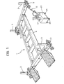
- a motor-vehicle platform lift of the four column type comprising four single-acting hydraulic lifting cylinders, all indicated by 2, arranged in correspondence with the four columns, all indicated by 3, of the lift 1.
- the platform lift 1 comprises a member 4 vertically movable under the action of the cylinders 2, and which in the example illustrated, is constituted by a checkout bench for repairing damaged motor-vehicle bodies.
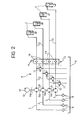
- the unit 5 comprises four hydraulic pumps, all indicated by 6, of equal displacement, which have intake pipelines 7 fitted with intake filters 8 and drawing from a common reservoir 9, and delivery pipelines 10 each fitted with a respective pressure relief valve 11, of conventional type, and connected to a respective lifting cylinder 2.
- the pumps 6 have coaxially-arranged drive shafts 6a, fast for rotation with each other and connected to an electric motor 12 for driving them in rotation.
- Valve means indicated in their entirety by 13 are provided in the pipelines 10, in a position between the pressure relief valves 11 and the cylinders 2. These means comprise four non-return valves 14 each having a respective closure member 15 movable within a valve body 16 to sealingly engage with a sealing seat 17.
- valves 14 are inserted in the pipelines 10 in such manner as to permit the passage of fluid from the pumps 6 to the cylinders 2 but to prevent the passage of fluid in the reverse direction.
- valve means 13 also comprise control means 18 for neutralising their operation; in particular these control means 18 comprise a shaft 19 with four eccentric cams 20 arranged to engage respective push-rods 21 of the closure members 15 whereby to displace them from their respective sealing seats 17 of the non-return valves 14.
- the hydraulic unit 5 is mounted on a portable structure 23, preferably in the form of a trolley provided with wheels 24.
- the electric motor 12 is caused to rotate in the sense indicated by arrow M ; this results in the pumps 6 being entrained in rotation and sending fluid under pressure to the cylinders 2 whereby the movable member 4 is raised.
- the movable member 4 descends under the action of its weight and the fluid contained in the cylinders 2 is expelled via the pipelines 10, causing the pumps 6 to rotate in a sense opposite to that above.
- the synchronisation of the lowering of the member 4 by the four cylinders 2 is ensured by the fact that the pumps 6 allow the passage of an equal volume of fluid therethrough as they are constrained to rotate at the same speed due to their shafts being fast for rotation with each other.
- the four-column type platform lift according to the invention possesses the required synchronisation of the four cylinders during raising and lowering of the movable member and,at the same time,is simple to construct and reliable in operation.
Landscapes
- Life Sciences & Earth Sciences (AREA)
- Engineering & Computer Science (AREA)
- Geology (AREA)
- Mechanical Engineering (AREA)
- Structural Engineering (AREA)
- Forklifts And Lifting Vehicles (AREA)
- Vehicle Body Suspensions (AREA)
Applications Claiming Priority (2)
| Application Number | Priority Date | Filing Date | Title |
|---|---|---|---|
| IT21642/81A IT1137390B (it) | 1981-05-12 | 1981-05-12 | Perfezionamento nei sollevatori a ponte per autoveicoli |
| IT21642 | 1981-05-12 |
Publications (2)
| Publication Number | Publication Date |
|---|---|
| EP0064958A2 true EP0064958A2 (de) | 1982-11-17 |
| EP0064958A3 EP0064958A3 (de) | 1985-01-09 |
Family
ID=11184742
Family Applications (1)
| Application Number | Title | Priority Date | Filing Date |
|---|---|---|---|
| EP82830124A Withdrawn EP0064958A3 (de) | 1981-05-12 | 1982-05-10 | Motorfahrzeug-Hubplattformen |
Country Status (3)
| Country | Link |
|---|---|
| EP (1) | EP0064958A3 (de) |
| AU (1) | AU8360382A (de) |
| IT (1) | IT1137390B (de) |
Cited By (2)
| Publication number | Priority date | Publication date | Assignee | Title |
|---|---|---|---|---|
| DE4421866C1 (de) * | 1994-06-22 | 1996-01-04 | Daimler Benz Aerospace Airbus | Hubvorrichtung |
| US10106378B2 (en) | 2015-11-03 | 2018-10-23 | General Electric Company | System and method for lifting with load moving machine |
Families Citing this family (1)
| Publication number | Priority date | Publication date | Assignee | Title |
|---|---|---|---|---|
| AUPN787096A0 (en) | 1996-02-05 | 1996-02-29 | Cornish, Mark Raymond | Elevational vehicle ramp |
Family Cites Families (11)
| Publication number | Priority date | Publication date | Assignee | Title |
|---|---|---|---|---|
| GB201242A (en) * | 1922-04-27 | 1923-07-27 | John Edward Hamilton | Improvements in and relating to hydraulic lifting & lowering apparatus |
| FR830019A (fr) * | 1937-03-17 | 1938-07-19 | Verboom & Durouchard Ets | Perfectionnements aux batteries de vérins hydrauliques |
| US2342311A (en) * | 1941-08-29 | 1944-02-22 | Globe Hoist Co | Vehicle hoist |
| US2602298A (en) * | 1949-09-01 | 1952-07-08 | Electrol Inc | Equalizing valve for plural motor systems |
| DE1007487B (de) * | 1954-03-26 | 1957-05-02 | Karl Eugen Bomm | Hydraulischer Antrieb einer Hebebuehne mit mehreren Hubstempeln |
| DE1003933B (de) * | 1955-07-25 | 1957-03-07 | Toussaint & Hess Gmbh | Hydraulische Steuerung fuer eine Vorrichtung zum Heben und Senken einer Plattform od. dgl. mittels hydraulischer Hubzylinder |
| US3381833A (en) * | 1965-10-30 | 1968-05-07 | Clark Equipment Co | Self-synchronizing load lifting and lowering system for straddle carriers and the like |
| GB1107250A (en) * | 1965-12-03 | 1968-03-27 | Kismet Ltd | Vehicle lifting systems |
| CH482626A (de) * | 1968-11-21 | 1969-12-15 | Javo Ag Werkzeug Und App Bau | Hubvorrichtung mit mindestens zwei Hebesäulen |
| CH521285A (de) * | 1970-03-24 | 1972-04-15 | Kraft Paul | Hydraulische Betätigungseinrichtung für eine Hebeeinrichtung |
| NL7713705A (nl) * | 1977-12-12 | 1979-06-14 | Itt | Gelijkloopinrichting voor hydraulische cilinders. |
-
1981
- 1981-05-12 IT IT21642/81A patent/IT1137390B/it active
-
1982
- 1982-05-10 EP EP82830124A patent/EP0064958A3/de not_active Withdrawn
- 1982-05-11 AU AU83603/82A patent/AU8360382A/en not_active Abandoned
Cited By (2)
| Publication number | Priority date | Publication date | Assignee | Title |
|---|---|---|---|---|
| DE4421866C1 (de) * | 1994-06-22 | 1996-01-04 | Daimler Benz Aerospace Airbus | Hubvorrichtung |
| US10106378B2 (en) | 2015-11-03 | 2018-10-23 | General Electric Company | System and method for lifting with load moving machine |
Also Published As
| Publication number | Publication date |
|---|---|
| EP0064958A3 (de) | 1985-01-09 |
| IT8121642A0 (it) | 1981-05-12 |
| IT1137390B (it) | 1986-09-10 |
| AU8360382A (en) | 1982-11-18 |
Similar Documents
| Publication | Publication Date | Title |
|---|---|---|
| US3632234A (en) | Method and apparatus for actuating a subsurface reciprocal well pump | |
| DE3325682C2 (de) | Förderpumpenantrieb | |
| DE60200435T2 (de) | Ziehkissen-Einrichtung | |
| US4462763A (en) | Hydraulic pump jack | |
| DE1476665B2 (de) | Mit einer vorrichtung zur aenderung der gewichtsmenge des im arbeitsraum befindlichen arbeitsmittels versehene heissgaskolbenmaschine | |
| US3958420A (en) | Air extracting system for hydraulic steering apparatus | |
| DE803020C (de) | Vorrichtung zum gleichzeitigen und gleichmaessigen Bewegen mehrerer hydraulischer Arbeitskolben | |
| DE2637347A1 (de) | Vorrichtung zum verstellen von lasten | |
| DE1899287U (de) | Fahrzeugfederung. | |
| DE3633530C2 (de) | ||
| US4043122A (en) | Fluid cam assembly | |
| DE1756769C3 (de) | Gleichlaufsteuerung, insbesondere für eine Kippbuhne zum Entladen von Fahrzeugen | |
| DE19709474A1 (de) | Hydraulische Hubeinrichtung | |
| EP0064958A3 (de) | Motorfahrzeug-Hubplattformen | |
| US4456438A (en) | Extrusion device for impregnating a rock formation, preferably for bonding with a liquid synthetic product | |
| DE2160449A1 (de) | Hydraulische Hubvorrichtung | |
| JPH0639285U (ja) | プレス用油圧回路 | |
| AT80389B (de) | Tiefbrunnenpumpe. Tiefbrunnenpumpe. | |
| EP0155592B1 (de) | Fluidpumpe | |
| DE349311C (de) | Hydraulischer Widerstandsregler fuer Kraftmaschinen | |
| DE810460C (de) | Kreislauffoerderpumpe | |
| AT51880B (de) | Einrichtung zum Entlüften des Treibmittels bei Flüssigkeitsgetrieben. | |
| DE618522C (de) | Hydraulischer Wagenheber mit Saug-, Rueckschlag- und Bremsventil | |
| DE1927568A1 (de) | Hydraulische Antriebsvorrichtung fuer zahnaerztliche Behandlungsstuehle | |
| DE2943370A1 (de) | Hydraulische hebebuehne |
Legal Events
| Date | Code | Title | Description |
|---|---|---|---|
| PUAI | Public reference made under article 153(3) epc to a published international application that has entered the european phase |
Free format text: ORIGINAL CODE: 0009012 |
|
| AK | Designated contracting states |
Designated state(s): AT BE CH DE FR GB LU NL SE |
|
| PUAL | Search report despatched |
Free format text: ORIGINAL CODE: 0009013 |
|
| AK | Designated contracting states |
Designated state(s): AT BE CH DE FR GB LI LU NL SE |
|
| STAA | Information on the status of an ep patent application or granted ep patent |
Free format text: STATUS: THE APPLICATION IS DEEMED TO BE WITHDRAWN |
|
| 18D | Application deemed to be withdrawn |
Effective date: 19850909 |
|
| RIN1 | Information on inventor provided before grant (corrected) |
Inventor name: BIGINI, ALBERTO |