EP0065042A1 - Energieerzeugung mit einem Arbeitsfluid und Regeneration eines Arbeitsfluids - Google Patents
Energieerzeugung mit einem Arbeitsfluid und Regeneration eines Arbeitsfluids Download PDFInfo
- Publication number
- EP0065042A1 EP0065042A1 EP81302177A EP81302177A EP0065042A1 EP 0065042 A1 EP0065042 A1 EP 0065042A1 EP 81302177 A EP81302177 A EP 81302177A EP 81302177 A EP81302177 A EP 81302177A EP 0065042 A1 EP0065042 A1 EP 0065042A1
- Authority
- EP
- European Patent Office
- Prior art keywords
- working fluid
- solvent solution
- stage
- regeneration
- regenerated
- Prior art date
- Legal status (The legal status is an assumption and is not a legal conclusion. Google has not performed a legal analysis and makes no representation as to the accuracy of the status listed.)
- Granted
Links
Images

Classifications
-
- F—MECHANICAL ENGINEERING; LIGHTING; HEATING; WEAPONS; BLASTING
- F01—MACHINES OR ENGINES IN GENERAL; ENGINE PLANTS IN GENERAL; STEAM ENGINES
- F01K—STEAM ENGINE PLANTS; STEAM ACCUMULATORS; ENGINE PLANTS NOT OTHERWISE PROVIDED FOR; ENGINES USING SPECIAL WORKING FLUIDS OR CYCLES
- F01K25/00—Plants or engines characterised by use of special working fluids, not otherwise provided for; Plants operating in closed cycles and not otherwise provided for
- F01K25/06—Plants or engines characterised by use of special working fluids, not otherwise provided for; Plants operating in closed cycles and not otherwise provided for using mixtures of different fluids
- F01K25/065—Plants or engines characterised by use of special working fluids, not otherwise provided for; Plants operating in closed cycles and not otherwise provided for using mixtures of different fluids with an absorption fluid remaining at least partly in the liquid state, e.g. water for ammonia
Definitions
- This invention relates to the generation of energy by means of a working fluid, and to the regeneration of a working fluid. More particularly, this invention relates to a method of and to apparatus for generating energy by means of a working fluid and for regenerating such a working fluid.
- expansion of the working fluid is controlled to provide a spent low pressure level at which the condensation temperature of the working fluid is greater than the temperature of the cooling medium, to permit condensation of the working fluid.
- regeneration is based on condensation of working fluid in a condenser wherein the working fluid is arranged to flow in heat exchange relationship with an available cooling medium. Because of the desire to achieve maximum expansion of the working fluid, regeneration of working fluid is often effected where the temperature difference between the condensation temperature of the spent working fluid at the spent level and the temperature of the available cooling medium is marginal-often as low as 1°C. This of necessity imposes a requirement for a large condenser with an extensive heat exchange surface, and for a large supply of cooling medium, thereby substantially adding to the operating costs.
- a method of generating energy which comprises expanding a gaseous working fluid from a charged high pressure level to a spent low pressure level to release energy, and regenerating the spent working fluid by, in at least one regeneration stage:
- a method of optimizing, within limits imposed by available sources of cooling and heating mediums, the energy supply capability of a gaseous working fluid which is expanded from a charged high pressure level to a spent low pressure level to provide available energy comprising expanding the gaseous working fluid to a spent low pressure level, and regenerating the spent working fluid by, in at least one regeneration stage:
- the spent working fluid may be regenerated in a plurality of successive regeneration stages by increasing the pressure in each stage until the working fluid has been regenerated to its charged state in the final regeneration stage.
- the spent working fluid may thus be regenerated by feeding it to a first regeneration stage, feeding the evaporated working fluid from each regeneration stage to a succeeding regeneration stage for further regeneration, and recycling within each regeneration stage the solvent solution remaining after evaporation of the working fluid in the evaporation stage of that regeneration stage for the recycled solvent solution to constitute the solvent the solvent solution for the absorption stage of that regeneration stage.
- the working fluid may be expanded to a spent low pressure level where the condensation temperature of the gaseous working fluid is below the minimum temperature of the cooling medium in the absorption stage.
- a method of optimizing, within limits imposed by available sources of cooling and heating mediums, the energy supply capability of a gaseous working fluid which is expanded from a charged high pressure level to a spent low pressure level to provide available energy comprising expanding the gaseous working fluid to a spent low pressure level, and regenerating the spent working fluid by, in a plurality of successive regeneration stages, condensing the working fluid and then evaporating the working fluid at an increased pressure, the working fluid being condensed in each regeneration stage by absorbing or dissolving it in a solvent solution while cooling with the cooling medium, the solvent solution comprising a solvent having, in each stage, an initial working fluid concentration which is sufficient to provide a solvent solution boiling range suitable for absorption of the working fluid, and the working fluid being evaporated in each stage by increasing the pressure to a level where the working fluid being regenerated can be evaporated with the available heating medium, and then evaporating the working fluid.
- the invention further extends to apparatus for generating energy, the apparatus comprising expansion means for expanding a gaseous working fluid from a charged high pressure level to a spent low pressure level to release energy, and a plurality of successive regeneration stages for regenerating such a spent working fluid, each regeneration stage comprising:
- the solvent solution in each regeneration stage is recycled, the solvent solution constitutes a closed loop in that stage, and is separate from the solvent solution in each other regeneration stage. Furthermore, in each regeneration stage, the quantity of working fluid being regenerated is dissolved in the solvent solution of that stage, and the equivalent quantity of working fluid being regenerated is evaporated from the solvent solution in the evaporation stage of each regeneration stage.
- the solvent of the solvent solution may be any suitable solvent which is a solvent for the working fluid, which has a boiling point above the maximum temperature which will be attained in any evaporation stage, and which will provide a solvent solution when working fluid is dissolved therein, which has a boiling point which decreases as the concentration of working fluid increases.
- the solvent solution is preferably a binary solution, it will be appreciated that it may be a solution of a plurality of liquids.
- the working fluid and solvent may be in the form of hydrocarbons having appropr.iate boiling points.
- the solvent may be in the form of butane or pentane while the working fluid may be in the form of propane.
- the working fluid may be an appropriate freon compound, with the solvent being an appropriate solvent for that compound.
- the working fluid is in the form of ammonia and the solvent is in the form of water.
- the boiling point of water is 100°C whereas the boiling point of pure ammonia is -33°C.
- concentration of ammonia in water increases, the boiling point of the aqueous ammonia solution will decrease. From binary phase diagrams of water and ammonia solutions, the appropriate initial concentration of ammonia in the solvent solution for each regeneration stage, can readily be determined for this invention from the pressure and temperature which will prevail in each condensation stage.
- the initial concentration of working fluid in the solvent solution in each regeneration stage, and the proportion of solvent solution to working fluid to be regenerated will be selected so that after complete absorption of the working fluid being regenerated in the absorption stage of that regeneration stage, the solvent solution will have a boiling point marginally above the minimum temperature attained in that absorption stage during use.
- the minimum quantity of solvent solution will be employed which will satisfy this requirement thereby reducing cooling medium requirements to the minimum, and thereby further reducing heating medium requirements to the minimum.
- the pressure is increased between the absorption and evaporation stages of each regeneration stage, to the maximum pressure at which the working fluid being regenerated can be evaporated effectively in the evaporation stage by the, or by a heating medium, available for heating the evaporation stage.
- the pressure is, therefore, preferably increased in each regeneration stage to the maximum level where the solvent solution in each evaporation stage will, after evaporation of the working fluid in that stage, have a boiling point marginally below the maximum temperature attainable in that evaporation stage.
- Control valve means may, however, be provided to control the quantity of evaporated working fluid which is fed from each regeneration stage to each succeeding regeneration stage. Thus, if a greater quantity of working fluid than that required for regeneration has been evaporated in an evaporator stage, only the required quantity will pass to the succeeding regeneration stage. The balance will be recycled with the solvent solution.
- the method of this invention may preferably include the step of, in each regeneration stage, feeding the solvent solution and evaporated working fluid from the evaporation stage to a separation stage for separating the working fluid being regenerated.
- the separator stage may be provided by a separator of any conventional suitable type known to those skilled in the art.
- the solvent solution which is recycled to the absorption stage in each regeneration stage is conveniently expanded to reduce its pressure to a pressure corresponding with or approaching that of the pressure of the working fluid being regenerated in that absorption stage.
- the solvent solution which is recycled in each regeneration stage, is recycled in heat exchange relationship with the evaporation stage to thereby reduce the heating medium requirements for the evaporation stage.
- the solvent solution which is recycled in each regeneration stage may be recycled at least partially in heat exchange relationship with the absorption stage.
- the cooling medium requirement will decrease because the quantity of heat to be removed will remain constant, but the capacity of the absorption stage will have to be increased. Conversely, if the recycled solvent solution is not recycled in heat exchange relationship with the absorption stage, the capacity of the absorption stage will decrease while the requirement of cooling medium will increase.
- the reduced cost of supplying lesser quantities of cooling medium can be balanced against the capital costs of increasing the capacity of the absorption stages to determine whether the recycled solvent solution should be recycled in heat exchange relationship, or at least partially in heat exchange relationship with the absorption stages, or not at all.
- all of the absorption stages of the regeneration stages may be carried out separately in a single composite absorption stage which is cooled by means of cooling medium from a common source.
- all of the evaporation stages may be carried out separately in a single composite evaporation stage which is heated by means of a heating medium from a common source.
- the apparatus of this invention may, therefore, include a single composite absorption unit and a single composite evaporation unit, with all the absorbers of the various regeneration stages being incorporated in the absorption unit, and all the evaporators of the various regeneration stages being incorporated in the evaporated unit.
- the invention can, therefore, have specific application where low temperature differential heating and cooling mediums are employed.
- a preferred application of the invention would, therefore, be in the field of thermal energy conversion using cool water withdrawn from a body of water as the cooling medium, and using, as heating medium, hot water from a body of water, water heated by solar heating, hot water heated additionally by solar heating means, or water or heating fluid in the form of waste heat fluids from industrial plants.
- a preferred application of the invention would, therefore, be in the field of ocean thermal energy conversion [OTEC] where ocean surface water is used as the heating medium and ocean water withdrawn from a sufficient depth from an ocean is used as the cooling medium, thereby resulting in a low temperature differential between the heating and cooling mediums.
- OEC ocean thermal energy conversion
- ocean water would be withdrawn from a depth of about 200 feet to provide the most economical cooling medium at the lowest temperature.
- the temperature does not tend to decrease significantly beyond a depth of about 200 feet.
- a further preferred application of the invention would be in regard to solar ponds for supplying the heating medium, and also the cooling medium if desired.
- the invention further extends to a method of increasing the pressure of a gaseous working fluid from an initial low pressure level to a high pressure level utilizing an available heating medium and utilizing an available cooling medium, which comprises incrementally increasing the pressure of the working fluid by, in a plurality of successive incremental regeneration stages:
- the expansion of the working fluid from a charged high pressure level to a spent low pressure level to release energy may be effected by any suitable conventional means known to those skilled in the art, and the energy so released may be stored or utilized in accordance with any of a number of conventional methods known to those skilled in the art.
- the working fluid may be expanded to drive a turbine of conventional type.
- the pressure of the solvent solution leaving the evaporation stage may be utilized to increase the pressure of the working fluid being regenerated which is introduced into the absorption stage with the recycled solvent solution.
- the solvent solution instead of expanding the solvent solution which is recycled to reduce its pressure to a pressure corresponding with or approaching that of the pressure of the working fluid being regenerated in an absorption stage, the solvent solution may be injected into the absorption stage in such a manner as to entrain the working fluid and draw the working fluid into the absorption stage.
- an injection system such as an injection nozzle having a restricted zone to create a zone of low pressure may be used.
- an injection nozzle having a restricted zone to create a zone of low pressure
- the working fluid will be introduced into the proximity of the restricted zone so that the reduced pressure created will permit the working fluid to be introduced into the absorption stage.
- the pressure, or at least part of the pressure, of the solvent solution which is recycled this will contribute to an increase in pressure in the absorption stage.
- This can provide the advantage of improving absorption in the absorption stage, or can be utilized to permit expansion of the working fluid to an even lower spent level.
- the initial increase in pressure provided by the solvent solution may be utilized to increase the pressure in the absorption stage, to a level where absorption can be effectively achieved in accordance with this invention.
- Applicant believes that this application of the pressure of the solvent solution will tend to be valuable in the first stage, and probably the first and second stages of a multi-stage regeneration system while, in a single stage system or a system employing only two stages it will tend to be less valuable. This will primarily be due to the fact that the mass ratio between the recycled solvent solution and the working fluid will not be sufficient.
- numeral 50 refers generally to apparatus for use in generating energy by the expansion of a gaseous working fluid from a charged high pressure level to a spent low pressure level to release energy, and for regenerating the spent working fluid.
- the apparatus 50 includes expansion means in the form of a turbine 52 in which a gaseous working fluid is expanded from a charged high pressure level to a spent low pressure level to released energy to drive the turbine 52.
- the gaseous working fluid at the high pressure level is fed to the turbine 52 along charged line 54 and is discharged from the turbine 52 along spent line 56.
- the apparatus 50 further includes regeneration means for regenerating the spent gaseous fluid.
- the regeneration means comprises four successive incremental regeneration stages.
- each regeneration stage has been identified by a letter followed by a suffix in arabic numerals indicating the particular regeneration stage.
- the flow lines for each regeneration stage have been identified by reference numerals having a prefix corresponding to that of the particular regeneration stage.
- the first regeneration stage comprises an absorber A1 for condensing the gaseous working fluid by dissolving it in a solvent solution, a pump P1 for pumping the solvent solution containing the dissolved working fluid to increase the pressure, evaporator E1 for evaporating the working fluid, and a separator S1 for separating the evaporated working fluid from the solvent solution.
- the first regeneration stage includes an influent line 1-1 into which the spent gaseous working fluid from the spent line 56 and solvent solution from a solvent solution recycle line 1-13 are fed into the first stage and through the absorber A1.
- the resultant solvent solution from the absorber A1 is fed along line 1-2 to the inlet of the pump P1.
- the solution is discharged from the pump P1 at an increased pressure along line 1-3 and through the evaporator El.
- the solvent solution and evaporated working fluid are fed from the evaporator E1 along line 1-4 to the separator S1.
- the separated evaporated working fluid is fed from the separator S1 along line 1-5 to the influent line 2-1 of the second stage.
- the solvent solution from the separator S1 is recycled along solvent solution recycle line 1-13 to the influent line 1-1.
- the second, third and fourth regeneration stages correspond exactly with the first regeneration stage except that the evaporated, separated working fluid from the separator S4 is withdrawn along line 4-5 and fed into the charged line 54 to repeat the cycle.
- the gaseous working fluid is ammonia
- the solvent is water
- the apparatus 50 is an apparatus for use in producing energy by ocean thermal energy conversion.
- the apparatus 50 is, therefore, conveniently installed on the seashore or on a floating platform.
- the apparatus 50 includes pump means [not shown] for pumping surface water from the surface of an ocean to the evaporators of the apparatus to constitute the heating medium for the apparatus, and includes pump means [not shown] for pumping cold water from a sufficient depth of such an ocean for constituting the cooling medium for cooling the absorbers of the apparatus 50.
- the absorber A1 includes circulation means having an inlet 1-9 and an outlet 1-10 for circulating deep ocean water through the absorber A1.
- the evaporator E1 includes an inlet 1-11 and an outlet 1-12 for circulating ocean surface water through the evaporator for heating the evaporator El.
- the recycle line 1-13, 2-13, 3-13 and 4-13 has an evaporator heat exchange line 1-15, 2-15, 3-15 and 4-15, respectively, passing in heat exchange relationship through the evaporator E.
- the solvent solution recycle line -13 may have a condenser heat exchange line 1-16, 2-16, 3-16 and 4-16, respectively, extending in heat exchange relationship through the absorber A or, alternatively, may completely bypass the absorber A as indicated by chain-dotted lines 1-18, 2-18, 3-18 and 4-18.
- recycled solvent solution passes in heat exchange relationship through the absorber of each-regeneration stage, it will assist in cooling the absorber and will thus reduce the quantity of cooling water required to effect the required cooling in that absorber since the quantity of heat to be transferred will remain constant. It will, however, necessitate an increase in the absorber capacity and thus, in the absorber size.
- the capital cost of an increase in absorber size can be balanced against the cost of the additional quantity of cooling medium to decide, on the basis of pure economics, as to whether the recycle line should pass through the absorbers, should completely bypass the absorbers, or should pass partially through the absorbers.
- the recycle lines will bypass the absorbers.
- the gaseous working fluid is ammonia
- the solvent solution is a solution of ammonia in water.
- the gaseous ammonia working fluid is indeed allowed to expand across the turbine 52 from a pressure of about nine atmospheres to a pressure of about one atmosphere.
- a specific quantity of gaseous working fluid to be regenerated, at a spent pressure level of one atmosphere is, therefore fed to the first stage along influent line 1-1.
- This quantity of gaseous working fluid is condensed in the absorber A1 by dissolving it in a solvent solution which is fed along solvent solution recycle line 1-13 into the influent line 1-1 at the same pressure of one atmosphere.
- the solvent solutions will not be passed in heat exchange relationship through the absorbers.
- the spent gaseous ammonia which may contain about 10% by weight of liquid ammonia, will be at a temperature of about -33°C, whereas the corresponding solvent solution will be at a temperature of about 8°C.
- the solvent solution comprises water having an initial ammonia concentration which is sufficient to provide a binary solution which at the pressure of one atmosphere, has a boiling point within the temperature range which will prevail in the absorber A1. Further, the proportion of solvent solution to the quantity of working fluid to be regenerated is such that after the solvent solution has dissolved the quantity of working fluid to be regenerated in the absorber A1, the resultant binary solution will have a concentration which will provide, at the pressure of one atmosphere, a boiling point marginally above the minimum temperature of the cooling medium. The boiling point of the solvent solution will thus be in the region of about 6°C where the minimum temperature of the cold water is about 4°C.
- the solvent solution containing the dissolved working fluid being regenerated will leave the absorber A1 at a temperature of about 6°C and at a pressure of one atmosphere, and is pumped by the pump P1 to the evaporator E1.
- the pump P1 is controlled to increase the pressure of the solvent solution to the maximum pressure at which the dissolved ammonia working fluid can be effectively evaporated in the evaporator El by means of the surface water heating medium at a maximum temperature of 27°C.
- the pressure increase is controlled so that after evaporation of the quantity of working fluid being regenerated, the solvent solution in the evaporator El will have a boiling point marginally below 27°C, such as about 25°C.
- This pressure can readily be determined from a binary water/ammonia phase diagram in relation to the prevailing ammonia concentration and temperature range in the evaporator El.
- the initial concentration of ammonia in water for the solvent solution as also the required quantity of solvent solution; which is fed to the absorber Al, can also readily be determined from such a phase diagram on the basis of the known pressure and temperature range.
- the evaporated working fluid and solvent solution are fed along line 1-4 to the separator S1, where they are allowed to separate.
- the solvent solution at a temperature of about 25°C will be recycled along the solvent solution recycle line 1-13 to constitute the solvent solution for the first stage.
- the separated, evaporated ammonia working fluid at about 25°C is fed from the separator S1 to the second regeneration stage along influent line 2-1.
- the quantity of working fluid being regenerated is mixed with a solvent solution recycled from a separator S2 of the second regeneration stage along the solvent solution recycle line 2-13 for dissolving the working fluid in the absorber A2.
- Each solvent solution recycle line 1-13, 2-13, 3-13 and 4-13 therefore, includes a pressure-reducing valve V1, V2, V3 and V4, respectively, for reducing the pressure of the recycled solvent solution to the same pressure as that of the influent working fluid being regenerated.
- the initial concentration of ammonia in the solvent solution will increase step-wise in correspondence with the step-wise increase in pressure provided by the pump means in each stage.
- the apparatus will include an appropriate number of regeneration stages until the quantity of working fluid being regenerated, has been regenerated to the appropriate charged high pressure level in a final regeneration stage such as the fourth regeneration stage shown in the drawing. It will further be appreciated that the spent pressure level to which the working fluid is expanded, will likewise determine the number of regeneration stages required. Thus if the working fluid is expanded to only say 3 atmospheres, only two or three regeneration stages may be required.
- the pump means P4 will increase the pressure of the solvent solution to about nine atmospheres thereby yielding a charged regenerated working fluid at a pressure of about nine atmospheres which is withdrawn from the separator S4 and fed along the charged line 54 to the turbine 52.
- the process will be carried out as a continuous process in which a constant quantity of working fluid by unit time is continuously being expanded across the turbine 52 and is then continuously being regenerated in the regeneration means.
- the energy required to operate the pumps was calculated to be 2.08 kcals/kg of working fluid regenerated.
- the gaseous working fluid can be expanded from a high pressure level of about nine atmospheres, to a low pressure level of about one atmosphere or less.
- the quantity of energy available for release is substantially greater than would be the case if the working fluid were expanded from a pressure of about nine atmospheres to a pressure of only about four or five atmospheres.
- the embodiment of the invention as illustrated in the drawing can provide a further advantage arising from the fact that the cold water requirements need only be sufficient to provide a final temperature in each absorber of about 6°C.
- the temperature of the cold water cooling medium can thus increase across each absorber as indicated in the above tables.
- the cooling medium requirements will be substantially less than would be the case if it were necessary to supply a sufficient quantity of cooling water at a sufficient rate to approach the Carnot cycle ideal where the cooling medium would remain at the constant minimum temperature.
- the same considerations apply to the heating medium, where the hot water is allowed to cool from about 27°C to the temperature indicated in the above tables across each evaporator stage thereby again providing a substantially reduced heating water requirement over that required by the ideal Carnot cycle operation.
- the absorbers of the four regeneration stages can conveniently be combined into-a single composite absorber through which the lines 1-1, 2-1, 3-1 and 4-1 pass separately for cooling by means of a single circulating supply of cold water.
- all the evaporators can be combined in a single composite evaporator heated by means of the circulating hot water from a single source.
- the quantity of solvent solution will have to be adjusted during use to compensate for varying conditions and for losses.
- the concentration of ammonia in water in each regeneration stage will have to be adjusted periodically in relation to seasonal variations in the minimum temperature of cold water and maximum temperature of hot water.
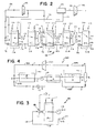
- numeral 150 refers generally to an alternative embodiment of the method and apparatus of this invention to the embodiment illustrated in Figure 1.
- the apparatus 150 corresponds substantially with the apparatus 50 and corresponding parts are indicated by corresponding reference numerals.
- a two-stage turbine system is employed comprising a first turbine 152 and a second turbine 153.
- the charged working fluid is partially expanded across the first turbine 152 into a heat exchange vessel 170.
- the partially expanded working fluid is led along separate conduits 171 and 172 through the absorber A2 and through the absorber A1 respectively in heat exchange relationship with the cooling water.
- the partially spent working fluid is further expanded across the second turbine 153 to its final spent level. It is then fed, as before, along the spent line 56 to the influent line 1-1.
- Applicant believes that by utilizing a two-stage turbine system with heat exchange of the partially expanded working fluid, the effectiveness of the system can be improved particularly where the system includes a number of regeneration stages. Applicant believes that it will tend to be less significant where fewer stages are employed.
- the drawing shows, to an enlarged scale, the apparatus of Figure 1 which has been adapted in the first and second regeneration stages for the pressure of the recycled solvent solution to be utilized in increasing the pressure of the influent spent working fluid into the absorption stage A1 and the absorption stage A2 respectively.
- the absorption stage A1 incorporates an injection system for injecting the recycled solvent solution at a pressure substantially higher than the pressure of the spent working fluid into the absorber A1.
- the injection system is in the form of an injection nozzle 180 having an intermediate restricted zone to generate a zone of low pressure.
- the spent line 56 joins the nozzle 180 at the restricted zone and, as is known those skilled in the art, in an attitude where the reduced pressure generated at the restricted zone by the solvent solution being injected through the nozzle 180 into the absorber A1, will draw the spent working fluid into the nozzle 180 and thus into the absorber A1.
- the ratio is to low, it will not be possible to introduce the total quantity of working fluid being regenerated by means of the flow of the solvent solution being recycled.
- the embodiment of the invention as illustrated in Figure 3 of the drawings can provide the advantage that the pressure of the solvent solution being recycled in the first and second stages respectively can be at least partially utilized to introduce the working fluid being regenerated, and to increase the pressure in the first and second absorbers A1 and A2.
- This affect can be utilized to improve the effectiveness of absorption in the first and second absorbers A1 and A2.
- this feature can be utilized to permit expansion of the charged working fluid to a yet lower pressure across the turbine 52, with reliance being placed on the pressure contribution of the solvent solution being recycled to raise the pressure in the absorber A1 to a level where effective absorption of the working fluid being regenerated can be effected.
- the working fluid introduced into the absorber A2 can be at a lower pressure, and reliance is placed on the pressure of the solvent solution being recycled into the absorber A2, to increase the pressure to a level for effective absorption in the absorber A2.
- Applicant believes that the injection system can be advantageous in the apparatus 50 particularly in the first and second stages, but would tend to have lesser value in subsequent stages.
- reference numeral 450 refers generally to yet a further alternative embodiment of the method and apparatus of this invention.
- the system 450 as illustrated in Figure 4 is designed for use where the charged working fluid is expanded to a relatively higher level than the level described with reference to Figures 1 to 3, but regeneration of the spent working fluid is effected in accordance with this invention to provide an economical system with high efficiency.
- the apparatus 450 includes a turbine 452, and absorber A, a pump P, a regenerator R, an evaporator E and a separator S.
- the spent working fluid expanded across the turbine 452 is fed along spent line 456 to influent line 464.
- Solvent solution which is recycled from the separator S along solvent solution recycle line 465 is fed through a pressure reducing valve V to reduce the pressure of the solvent solution to that of the spent working fluid, and then into the absorber A through the influent line 464.
- cooling medium in the form of cold deep ocean water is circulated in heat exchange relationship through the absorber A by means of conduit 461, while heating surface water is circulated through evaporator E in heat exchange relationship therewith, along conduit 463.
- the spent working fluid is absorbed by the solvent solution in the absorber A whereafter the solvent solution containing the absorbed working fluid has its pressure increased by the pump P.
- the solvent solution containing the absorbed working fluid is fed from the pump P along line 466 through the regenerator R and then to the evaporator E for evaporation of the dissolved working fluid being regenerated.
- the solvent solution being recycled along the line 465 is passed in heat exchange relationship with the solvent solution passed through the regenerator R to -effect heat exchange.
- the evaporated fluid being regenerated and the solvent solution passes to the separator S for separation, whereafter the separated charged working fluid is fed along charged line 454 to the turbine 452.
- the working fluid is expanded from a charged level of 9 atmospheres to a spent level of 5.5 atmospheres. It will further be noted that the spent working fluid and solvent solution enter the absorber A at a temperature of 12°C, and that the solvent solution containing the absorbed working fluid being regenerated, leaves the absorber A at a temperature of about 8°C.
- absorption of the ammonia working fluid can commence in the absorber A at a temperature of 12°C or slightly higher, and complete absorption will have occurred by the time the temperature has been reduced to about 8°C by the cooling medium at 4°C.
- condensation of gaseous ammonia at 5.5 atmospheres would only commence at a temperature of about 5°C resulting in a marginal difference of 1°C between the temperature of condensation and the temperature of the available cooling medium, which is at 4°C.
- the temperature of the working fluid would have to be reduced to about 5°C by the cooling medium at 4°C. It will be appreciated that because of the marginal temperature difference, the requirements of cooling water will be substantial and a substantial heat transfer surface will be required.
- the cooling water requirements, the heat transfer surface area, and the temperature difference between the temperature of the cooling water and the temperature required for complete absorption of the spent working fluid can be balanced to achieve the most economical system in the light of the operating parameters and capital costs.
- the system 450 therefore provides the advantage of an increased enthalpy drop across the turbine 452 and provides a system of increased efficiency and economy.
Landscapes
- Engineering & Computer Science (AREA)
- Chemical & Material Sciences (AREA)
- Combustion & Propulsion (AREA)
- Mechanical Engineering (AREA)
- General Engineering & Computer Science (AREA)
- Engine Equipment That Uses Special Cycles (AREA)
Priority Applications (4)
| Application Number | Priority Date | Filing Date | Title |
|---|---|---|---|
| EP81302177A EP0065042B1 (de) | 1981-05-15 | 1981-05-15 | Energieerzeugung mit einem Arbeitsfluid und Regeneration eines Arbeitsfluids |
| DE8181302177T DE3173962D1 (en) | 1981-05-15 | 1981-05-15 | Generation of energy by means of a working fluid, and regeneration of a working fluid |
| GB8114927A GB2098666A (en) | 1981-05-15 | 1981-05-15 | Generation of energy by means of a working fluid and regeneration of a working fluid |
| FR8110391A FR2506386A1 (fr) | 1981-05-15 | 1981-05-21 | Procede et dispositif pour la production d'energie au moyen d'un fluide actif et regeneration du fluide actif apres utilisation |
Applications Claiming Priority (1)
| Application Number | Priority Date | Filing Date | Title |
|---|---|---|---|
| EP81302177A EP0065042B1 (de) | 1981-05-15 | 1981-05-15 | Energieerzeugung mit einem Arbeitsfluid und Regeneration eines Arbeitsfluids |
Publications (2)
| Publication Number | Publication Date |
|---|---|
| EP0065042A1 true EP0065042A1 (de) | 1982-11-24 |
| EP0065042B1 EP0065042B1 (de) | 1986-03-05 |
Family
ID=8188303
Family Applications (1)
| Application Number | Title | Priority Date | Filing Date |
|---|---|---|---|
| EP81302177A Expired EP0065042B1 (de) | 1981-05-15 | 1981-05-15 | Energieerzeugung mit einem Arbeitsfluid und Regeneration eines Arbeitsfluids |
Country Status (4)
| Country | Link |
|---|---|
| EP (1) | EP0065042B1 (de) |
| DE (1) | DE3173962D1 (de) |
| FR (1) | FR2506386A1 (de) |
| GB (1) | GB2098666A (de) |
Cited By (6)
| Publication number | Priority date | Publication date | Assignee | Title |
|---|---|---|---|---|
| WO1985003975A1 (fr) * | 1980-06-19 | 1985-09-12 | Sonnleitner, Ingolf | Pompe a chaleur a absorption |
| EP0472020A1 (de) * | 1990-08-15 | 1992-02-26 | Exergy, Inc. | Methode und Vorrichtung zur Umwandlung von Niedertemperaturwärme in elektrische Energie |
| US5440882A (en) * | 1993-11-03 | 1995-08-15 | Exergy, Inc. | Method and apparatus for converting heat from geothermal liquid and geothermal steam to electric power |
| WO2002101206A1 (en) * | 2001-06-12 | 2002-12-19 | Midwest Research Institute | Stratified vapor generator |
| US7305829B2 (en) | 2003-05-09 | 2007-12-11 | Recurrent Engineering, Llc | Method and apparatus for acquiring heat from multiple heat sources |
| US8117844B2 (en) | 2004-05-07 | 2012-02-21 | Recurrent Engineering, Llc | Method and apparatus for acquiring heat from multiple heat sources |
Families Citing this family (6)
| Publication number | Priority date | Publication date | Assignee | Title |
|---|---|---|---|---|
| IL67389A0 (en) * | 1982-12-01 | 1983-05-15 | Gason Energy Eng Ltd | Method and apparatus for the absorption of a gas in a liquid |
| US4503682A (en) * | 1982-07-21 | 1985-03-12 | Synthetic Sink | Low temperature engine system |
| FR2607581B1 (fr) * | 1986-12-02 | 1989-01-13 | Ancet Victor | Convertisseur de chaleur ambiante |
| EP0328103A1 (de) * | 1988-02-12 | 1989-08-16 | Babcock-Hitachi Kabushiki Kaisha | Hybridisches Rankin-Zyklus-System |
| AU6719690A (en) * | 1989-11-20 | 1991-06-13 | Vasilios Styliaras | Heat conversion into mechanical work through absorption-desorption |
| GR1000546B (el) * | 1989-11-20 | 1992-08-25 | Vasileios Styliaras | Μετατροπη θερμοτητας σε μηχανικη ενεργεια μεσω δεσμευσης (π.χ.απορροφηση-εκροφηση)εργαζομενου αεριου απο μιγμα ουσιων. |
Citations (3)
| Publication number | Priority date | Publication date | Assignee | Title |
|---|---|---|---|---|
| GB294882A (en) * | 1927-07-30 | 1929-09-12 | Gen Electric | Improvements in and relating to vapour engines |
| DE503537C (de) * | 1927-05-15 | 1930-07-24 | Eduard Fuchs | Mittels Ammoniakgases betriebene Kraftanlage |
| DE2801835A1 (de) * | 1978-01-17 | 1979-07-19 | Dietrich E Dipl Ing Singelmann | Zwei- und mehrkreissystem - kraftwerk mit heterogenverdampfung |
-
1981
- 1981-05-15 DE DE8181302177T patent/DE3173962D1/de not_active Expired
- 1981-05-15 EP EP81302177A patent/EP0065042B1/de not_active Expired
- 1981-05-15 GB GB8114927A patent/GB2098666A/en not_active Withdrawn
- 1981-05-21 FR FR8110391A patent/FR2506386A1/fr not_active Withdrawn
Patent Citations (3)
| Publication number | Priority date | Publication date | Assignee | Title |
|---|---|---|---|---|
| DE503537C (de) * | 1927-05-15 | 1930-07-24 | Eduard Fuchs | Mittels Ammoniakgases betriebene Kraftanlage |
| GB294882A (en) * | 1927-07-30 | 1929-09-12 | Gen Electric | Improvements in and relating to vapour engines |
| DE2801835A1 (de) * | 1978-01-17 | 1979-07-19 | Dietrich E Dipl Ing Singelmann | Zwei- und mehrkreissystem - kraftwerk mit heterogenverdampfung |
Cited By (8)
| Publication number | Priority date | Publication date | Assignee | Title |
|---|---|---|---|---|
| WO1985003975A1 (fr) * | 1980-06-19 | 1985-09-12 | Sonnleitner, Ingolf | Pompe a chaleur a absorption |
| EP0160109A1 (de) * | 1980-06-19 | 1985-11-06 | Sonnleitner, Ingolf | Absorptionswärmepumpe |
| EP0472020A1 (de) * | 1990-08-15 | 1992-02-26 | Exergy, Inc. | Methode und Vorrichtung zur Umwandlung von Niedertemperaturwärme in elektrische Energie |
| US5440882A (en) * | 1993-11-03 | 1995-08-15 | Exergy, Inc. | Method and apparatus for converting heat from geothermal liquid and geothermal steam to electric power |
| WO2002101206A1 (en) * | 2001-06-12 | 2002-12-19 | Midwest Research Institute | Stratified vapor generator |
| US7373904B2 (en) | 2001-06-12 | 2008-05-20 | Midwest Research Institute | Stratified vapor generator |
| US7305829B2 (en) | 2003-05-09 | 2007-12-11 | Recurrent Engineering, Llc | Method and apparatus for acquiring heat from multiple heat sources |
| US8117844B2 (en) | 2004-05-07 | 2012-02-21 | Recurrent Engineering, Llc | Method and apparatus for acquiring heat from multiple heat sources |
Also Published As
| Publication number | Publication date |
|---|---|
| DE3173962D1 (en) | 1986-04-10 |
| GB2098666A (en) | 1982-11-24 |
| EP0065042B1 (de) | 1986-03-05 |
| FR2506386A1 (fr) | 1982-11-26 |
Similar Documents
| Publication | Publication Date | Title |
|---|---|---|
| US4346561A (en) | Generation of energy by means of a working fluid, and regeneration of a working fluid | |
| EP0065042B1 (de) | Energieerzeugung mit einem Arbeitsfluid und Regeneration eines Arbeitsfluids | |
| CA1205641A (en) | Low temperature engine system | |
| US10092851B2 (en) | System and method for water treatment | |
| US4291232A (en) | Liquid powered, closed loop power generating system and process for using same | |
| EP0037665B1 (de) | Verfahren und Vorrichtung zur Gewinnung von Acetylen | |
| EP0059748B1 (de) | Durch eine umkehrabsorptionswärmepumpe verbessertes destillationsverfahren | |
| US4315402A (en) | Heat transfer process and system | |
| US3489652A (en) | Desalination process by multi-effect,multi-stage flash distillation combined with power generation | |
| Sharan et al. | Optimal feed flow sequence for multi-effect distillation system integrated with supercritical carbon dioxide Brayton cycle for seawater desalination | |
| US4586340A (en) | Method and apparatus for implementing a thermodynamic cycle using a fluid of changing concentration | |
| US4078976A (en) | Solar potable water recovery and power generation from salinous water | |
| US3288686A (en) | Method for multi-flash evaporation to obtain fresh water from aqueous solution | |
| US4084379A (en) | Energy conversion system | |
| US3076096A (en) | Conversions of sea water and generating systems | |
| CN103803668A (zh) | 剩余氨水蒸氨塔顶氨蒸汽余热回收系统 | |
| US3844899A (en) | Multistage flash distillation | |
| US3329583A (en) | Method for producing pure water from sea water and other solutions by flash vaporization and condensation | |
| US3637465A (en) | Distillation method having counterflow heat exchange with condensate | |
| US4458499A (en) | Absorption heat pump system | |
| US4458500A (en) | Absorption heat pump system | |
| BE1026296B9 (nl) | Absorptiesysteem met gesloten cyclus en werkwijze voor het afkoelen en genereren van stroom | |
| US3856631A (en) | Process and apparatus for separating water from non-volatile solutes | |
| CA1173257A (en) | Generation of energy by means of a working fluid and regeneration of a working fluid | |
| US4272961A (en) | Recovery of energy from geothermal brine and other aqueous sources |
Legal Events
| Date | Code | Title | Description |
|---|---|---|---|
| PUAI | Public reference made under article 153(3) epc to a published international application that has entered the european phase |
Free format text: ORIGINAL CODE: 0009012 |
|
| AK | Designated contracting states |
Designated state(s): CH DE FR GB IT NL SE |
|
| 17P | Request for examination filed |
Effective date: 19830307 |
|
| ITF | It: translation for a ep patent filed | ||
| GRAA | (expected) grant |
Free format text: ORIGINAL CODE: 0009210 |
|
| AK | Designated contracting states |
Kind code of ref document: B1 Designated state(s): CH DE FR GB IT LI NL SE |
|
| REF | Corresponds to: |
Ref document number: 3173962 Country of ref document: DE Date of ref document: 19860410 |
|
| ET | Fr: translation filed | ||
| PLBE | No opposition filed within time limit |
Free format text: ORIGINAL CODE: 0009261 |
|
| STAA | Information on the status of an ep patent application or granted ep patent |
Free format text: STATUS: NO OPPOSITION FILED WITHIN TIME LIMIT |
|
| 26N | No opposition filed | ||
| ITTA | It: last paid annual fee | ||
| EAL | Se: european patent in force in sweden |
Ref document number: 81302177.1 |
|
| PGFP | Annual fee paid to national office [announced via postgrant information from national office to epo] |
Ref country code: SE Payment date: 19980420 Year of fee payment: 18 Ref country code: FR Payment date: 19980420 Year of fee payment: 18 |
|
| PGFP | Annual fee paid to national office [announced via postgrant information from national office to epo] |
Ref country code: DE Payment date: 19980421 Year of fee payment: 18 |
|
| PGFP | Annual fee paid to national office [announced via postgrant information from national office to epo] |
Ref country code: GB Payment date: 19980427 Year of fee payment: 18 |
|
| PGFP | Annual fee paid to national office [announced via postgrant information from national office to epo] |
Ref country code: NL Payment date: 19980430 Year of fee payment: 18 |
|
| PGFP | Annual fee paid to national office [announced via postgrant information from national office to epo] |
Ref country code: CH Payment date: 19980505 Year of fee payment: 18 |
|
| PG25 | Lapsed in a contracting state [announced via postgrant information from national office to epo] |
Ref country code: GB Free format text: LAPSE BECAUSE OF NON-PAYMENT OF DUE FEES Effective date: 19990515 |
|
| PG25 | Lapsed in a contracting state [announced via postgrant information from national office to epo] |
Ref country code: SE Free format text: LAPSE BECAUSE OF NON-PAYMENT OF DUE FEES Effective date: 19990516 |
|
| PG25 | Lapsed in a contracting state [announced via postgrant information from national office to epo] |
Ref country code: LI Free format text: LAPSE BECAUSE OF NON-PAYMENT OF DUE FEES Effective date: 19990531 Ref country code: CH Free format text: LAPSE BECAUSE OF NON-PAYMENT OF DUE FEES Effective date: 19990531 |
|
| PG25 | Lapsed in a contracting state [announced via postgrant information from national office to epo] |
Ref country code: NL Free format text: LAPSE BECAUSE OF NON-PAYMENT OF DUE FEES Effective date: 19991201 |
|
| REG | Reference to a national code |
Ref country code: CH Ref legal event code: PL |
|
| GBPC | Gb: european patent ceased through non-payment of renewal fee |
Effective date: 19990515 |
|
| EUG | Se: european patent has lapsed |
Ref document number: 81302177.1 |
|
| PG25 | Lapsed in a contracting state [announced via postgrant information from national office to epo] |
Ref country code: FR Free format text: LAPSE BECAUSE OF NON-PAYMENT OF DUE FEES Effective date: 20000131 |
|
| NLV4 | Nl: lapsed or anulled due to non-payment of the annual fee |
Effective date: 19991201 |
|
| PG25 | Lapsed in a contracting state [announced via postgrant information from national office to epo] |
Ref country code: DE Free format text: LAPSE BECAUSE OF NON-PAYMENT OF DUE FEES Effective date: 20000301 |
|
| REG | Reference to a national code |
Ref country code: FR Ref legal event code: ST |