EP0065180A1 - Dispositif de vissage de bouchons pour fûts - Google Patents
Dispositif de vissage de bouchons pour fûts Download PDFInfo
- Publication number
- EP0065180A1 EP0065180A1 EP82103811A EP82103811A EP0065180A1 EP 0065180 A1 EP0065180 A1 EP 0065180A1 EP 82103811 A EP82103811 A EP 82103811A EP 82103811 A EP82103811 A EP 82103811A EP 0065180 A1 EP0065180 A1 EP 0065180A1
- Authority
- EP
- European Patent Office
- Prior art keywords
- centering
- screwing
- plug
- screw head
- plate
- Prior art date
- Legal status (The legal status is an assumption and is not a legal conclusion. Google has not performed a legal analysis and makes no representation as to the accuracy of the status listed.)
- Granted
Links
- 230000006978 adaptation Effects 0.000 abstract 1
- 238000007789 sealing Methods 0.000 description 4
- 238000010276 construction Methods 0.000 description 2
- 238000000034 method Methods 0.000 description 2
- 239000000725 suspension Substances 0.000 description 2
- 230000005540 biological transmission Effects 0.000 description 1
- 230000015572 biosynthetic process Effects 0.000 description 1
- 238000011161 development Methods 0.000 description 1
- 230000018109 developmental process Effects 0.000 description 1
- 238000005755 formation reaction Methods 0.000 description 1
- 239000007788 liquid Substances 0.000 description 1
- 239000000463 material Substances 0.000 description 1
Images
Classifications
-
- B—PERFORMING OPERATIONS; TRANSPORTING
- B65—CONVEYING; PACKING; STORING; HANDLING THIN OR FILAMENTARY MATERIAL
- B65B—MACHINES, APPARATUS OR DEVICES FOR, OR METHODS OF, PACKAGING ARTICLES OR MATERIALS; UNPACKING
- B65B7/00—Closing containers or receptacles after filling
- B65B7/16—Closing semi-rigid or rigid containers or receptacles not deformed by, or not taking-up shape of, contents, e.g. boxes or cartons
- B65B7/28—Closing semi-rigid or rigid containers or receptacles not deformed by, or not taking-up shape of, contents, e.g. boxes or cartons by applying separate preformed closures, e.g. lids, covers
- B65B7/2828—Closing semi-rigid or rigid containers or receptacles not deformed by, or not taking-up shape of, contents, e.g. boxes or cartons by applying separate preformed closures, e.g. lids, covers inserting and rotating screw stoppers
Definitions
- the invention relates to a plug screwing device for barrels.
- drums intended for filling with liquids are delivered with a screwed-on sealing plug. It is therefore necessary to remove it and screw it back on after filling.
- the filling device - the drums must be aligned precisely, otherwise there is a risk that the filling material will not flow into the bunghole, but next to it onto the drum.
- the opening and closing of the bung holes is very labor-intensive in known filling devices.
- a closing device For closing the fill opening of a barrel or the like. with the aid of a device for inserting and fastening a stopper in the filling opening, a closing device is known in which both the device for inserting the stopper and a position determining device are arranged at a distance from one another in such a way that they are upwards and downwards and according to polar coordinates with respect to one another fixed point are freely movable in a plane perpendicular to the upward and downward movement.
- a gripping device is provided to prevent the free movement of the devices for inserting the plug and for determining the position together, and a drive device which is suitable for the two devices for inserting the plug and for determining the position when the gripping device free movement prevents moving only linearly and forcibly by a distance equal to the distance between the two devices.
- This locking device has very large dimensions. To achieve sufficient strength and for precise storage of the movable components the construction is very complex. Furthermore, the energy requirement for the operation of this locking device is very large, since when centering the entire frame on the support device must always be pivoted about an axis (DE-OS 18 17 237).
- a device for closing containers with an eccentrically arranged pouring spout which by a drive machine that can be moved between a rest position and a working position, in which a centering device carried by this drive machine engages in the periphery of the lid wall of the container, the one has eccentric pouring spout, such that a rotatable power output shaft of the drive machine is brought into a position coaxial to the container and held therein, a scanning device which is held eccentrically by the shaft and as part of the shaft is displaceable with it by a circumference, the center point of which the container axis and whose radius is equal to the distance between the axis of the spout and the container axis, up to an engagement position with the spout, and by a sealing head, which is held eccentrically by the shaft in a coaxial position to the scanning device and along its own A axis between a rest position and a working position in which there is an engagement with the spout, can be moved.
- this device With this device, the closing of containers with eccentric spouts is possible, the scanning of the position of the spout being carried out with a device which facilitates and accelerates this scanning, while at the same time it is intended to achieve with another device that the entire working cycle of the device is complete expires automatically.
- this known device has a variety of complicated components (DE-OS 22 10 753).
- Another device for attaching screw caps to the bung holes of drums with a boom that can be moved vertically by a lifting device and pivoted about a vertical axis, and with a centering device and a locking device that can be brought one after the other over the bung hole of a barrel by pivoting the boom Formed in such a way that the centering device is detachably connected to the boom by means of a receiving flange and a holding tube is arranged on the receiving flange with outer-wall-shaped joints for search fingers, the shafts of which are guided through openings in the jacket of the holding tube and by means of an elastic ring made of rubber or .
- a centering device and a locking device that can be brought one after the other over the bung hole of a barrel by pivoting the boom Formed in such a way that the centering device is detachably connected to the boom by means of a receiving flange and a holding tube is arranged on the receiving flange with outer-wall-shaped joints for search fingers, the shafts of
- the invention solves the problem of creating a plug screwing device for barrels which automatically centers the screw head on the barrel bung hole and compensates for an inclined position of the sealing plug.
- a plug screwing device for barrels which is designed according to the invention in such a way that the device has a centering and screwing head with an outer centering ring and with a screw head arranged in the interior thereof, against which the centering ring provided with a stopper holding device against Spring pressure can be raised and is connected to a drive device via a drive shaft with an intermediate double universal joint.
- the plug screwing device consists of a support frame with an upper support plate and a lower support plate, on which a centering plate with an annular opening tapering in the direction of the centering and screwing head is arranged, into which a is used correspondingly profiled molded body, which carries the centering ring at its bottom end and which is connected to a section above the centering plate with a guide plate which is held on at least three guide bolts fastened to the lower support plate of the support frame against the pressure of springs, that the screw head is connected to the drive device via a drive shaft rotatably mounted with the molded body, and that the drive shaft has the double universal joint.
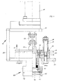
- a support frame 20 which is designed as a U-shaped bracket and has a lower support plate 21 and an upper support plate 22 arranged above it.
- the inner wall surface 25 delimiting the opening 24 is conically tapered towards the bottom det, whereby, as indicated in FIG. 1 at 25a, this conical inner wall surface 25 can merge into a vertical lower wall section.
- a shaped body 30 is inserted, which has a conically tapering downward outer wall surface 35, so that when the shaped body 30 is inserted into the annular opening 24, the conical outer wall surface 35 of the shaped body 30 on the conical inner wall surface 25 of the centering plate 23 abuts.
- the molded body 30 is extended towards the bottom and carries at its free end a centering ring 40, the annular inner wall surface 45 of which is conical.
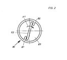
- This interior enclosed by the centering ring 40 serves to receive a stopper 80, as shown in FIG. 2.
- the centering ring 40 has a stopper holding device 41 which is designed as a suction device and which is connected to a vacuum generating device via a connecting piece indicated at 42. By means of this suction device, the stopper 80 to be screwed on is gripped and held by the centering ring 40.
- the molded body 30 is formed to extend upwards on the centering plate 23 and connected to a guide plate 36 which rests on the centering plate 23rd
- This guide plate 36 is held on guide pins 28 such that the guide plate 36 is displaceable in the direction of arrow X and can thus be raised.
- three guide bolts 28 are provided, which are attached to the lower support plate 21 of the support frame 20 and distributed through the centering plate 23, distributed at the same distance.
- the guide bolts 28 carry springs 29 on their shafts which are supported on the guide plate 36 in such a way that when the guide plate 36 is raised in the direction of the arrow X, the springs 29 are compressed, with the result that, after a pressure exerted on the centering ring 40 from below by means of the springs 29, the guide plate 36 with the molded body 30 and the centering ring 40 is moved back into its starting position .
- the centering and screwing head 100 with the centering ring 40 also receives the screwing head 50, which is freely rotatable and longitudinally displaceable in the interior of the centering ring 40 (FIG. 1).
- This screw head 50 is driven by a drive shaft 51 from a drive device 60 which is arranged in the support frame 20 on the upper support plate 22.
- the drive shaft 51 leading to the screw head 50 is guided through a central longitudinal bore in the molded body 30.
- the molded body 30 is then sleeve-shaped to create the longitudinal bore through which the drive shaft 51 is guided.
- the drive shaft 51 is supported by means of bushings, seals and the like.
- the drive shaft 51 consists of two shaft sections which are connected via a double universal joint 55. Due to the use of this double universal joint 55, it is possible that the screw head 50 can be aligned to all inclined positions of the plug.
- the screw head 50 has a driving tongue 52 in its lower region, which will be discussed in more detail below (FIGS. 1 and 2).
- the plug-in screwing device works as follows: First, the screw plug 80 is lowered separately via a pneumatically operated distributor, not shown in the drawing, under the centering and screwing head 100 by means of pneumatic cylinders. Is that aligned beforehand Te barrel driven with its bung hole under the centering and screwing head 100, the centering and screwing head 100 lowers on the screwing plug and this is sucked in by vacuum in the interior of the centering ring 40. This process is controlled over time. After the time has elapsed, the stopper delivery for taking over the next screw stopper will move back. The centering and screw head is moved by means of another air cylinder over the bung hole of the barrel. The centering ring 40 is used for centering.
- the centering ring 40 then lifts out of its guide in the molded body 30 and aligns itself with the bung hole, the screw head 50 being able to adapt to the centering movements of the centering ring 40 through its cardanic suspension.
- the actual screw head 50 stops; he can still adjust inclinations of the screw plug due to its gimbal, so that inclinations can thus be compensated.
- the centering ring 40 is lifted out of its guide in the centering plate 23, an alignment of the screw plug 50 by means of the cardanic suspension by means of the double universal joint 55 is also possible. It is aligned with the bung hole and the stopper.
- the screw head 50 remains in its position since it does not take part in the lifting movement of the shaped body 30 with the centering ring 40. Because the screw head 50 does not take part in this lifting movement, the screw head can engage with the driving tongue 52 in the screw plug 80, as can be seen in FIG. 2.
- the double universal joint 55 also enables automatic alignment to an inclined position of the stopper.
- the screw plug 80 is formed in a manner known per se and has in its upper cover surface a disk-shaped depression 83, in the area of which two are ge Opposing bulge-like projections 81, 82 are arranged so that the catch tongue 52 of the screw head 50 is approximately diagonally arranged on the one projection 81 and the other on the other projection 82 so that when the screw head 50 rotates in the direction of the arrow X1 the plug 80 also participates in this rotary movement.
- the screw head 50 when lifting the centering and screwing head 100, i.e. of the centering ring 40, the screw head 50 with the driving tongue 52 and can thus engage in the formations or drivers 81, 82 of the sealing plug 80.
- the drive device 60 is switched on via a pneumatic timer (not shown in the drawing), as a result of which the screw head 50 is rotated.
- the vacuum line of the suction device or stopper holding device 41 is vented and the stopper is screwed into the thread of the stopper hole connector arranged on the stopper hole.
- the screwing process is ended via an adjustable torque switch, the centering and screwing head 100 moves back into its starting position, i.e. the screw head 50 and the centering ring 40 assume the position shown in FIG. 1.
- the centering and screwing head 100 When the centering and screwing head 100 has reached its starting position, the centering and screwing head is available for receiving and screwing in a further screwing plug.
Landscapes
- Engineering & Computer Science (AREA)
- Mechanical Engineering (AREA)
- Sealing Of Jars (AREA)
- Details Of Spanners, Wrenches, And Screw Drivers And Accessories (AREA)
Priority Applications (1)
| Application Number | Priority Date | Filing Date | Title |
|---|---|---|---|
| AT82103811T ATE8369T1 (de) | 1981-05-14 | 1982-05-04 | Stopfeneinschraubgeraet fuer faesser. |
Applications Claiming Priority (2)
| Application Number | Priority Date | Filing Date | Title |
|---|---|---|---|
| DE3119286A DE3119286C2 (de) | 1981-05-14 | 1981-05-14 | Stopfeneinschraubgerät für Fässer |
| DE3119286 | 1981-05-14 |
Publications (2)
| Publication Number | Publication Date |
|---|---|
| EP0065180A1 true EP0065180A1 (fr) | 1982-11-24 |
| EP0065180B1 EP0065180B1 (fr) | 1984-07-11 |
Family
ID=6132350
Family Applications (1)
| Application Number | Title | Priority Date | Filing Date |
|---|---|---|---|
| EP82103811A Expired EP0065180B1 (fr) | 1981-05-14 | 1982-05-04 | Dispositif de vissage de bouchons pour fûts |
Country Status (5)
| Country | Link |
|---|---|
| US (1) | US4497155A (fr) |
| EP (1) | EP0065180B1 (fr) |
| JP (1) | JPS6015558B2 (fr) |
| AT (1) | ATE8369T1 (fr) |
| DE (1) | DE3119286C2 (fr) |
Cited By (2)
| Publication number | Priority date | Publication date | Assignee | Title |
|---|---|---|---|---|
| DE3529773A1 (de) * | 1985-08-20 | 1987-03-05 | Siegfried Heyng | Schraubvorrichtung zum anschrauben von verschlussdeckeln an spundloechern von faessern |
| EP0308528A1 (fr) * | 1987-09-23 | 1989-03-29 | Gerhard Arnemann | Dispositif pour le vissage et le dévissage de fermetures à vis ou similaires dans ou hors des ajutages de remplissage de fûts, récipients ou similaires |
Families Citing this family (7)
| Publication number | Priority date | Publication date | Assignee | Title |
|---|---|---|---|---|
| DE3715795A1 (de) * | 1987-05-12 | 1988-11-24 | Feige Gmbh | Schrauber fuer spundlochschraubdeckel von faessern |
| DE3804276A1 (de) * | 1988-02-11 | 1989-08-24 | Wiederaufarbeitung Von Kernbre | Vorrichtung zum verschrauben zweier komponenten, die hohes gewicht und eine gemeinsame vertikale achse haben, insbesondere zum verschrauben eines deckels mit einem behaelter zum transport und/oder lagerung von radioaktiven stoffen |
| DE8908259U1 (de) * | 1989-07-06 | 1990-11-15 | Kuka Schweissanlagen + Roboter Gmbh, 8900 Augsburg | Haltevorrichtung für Muttern oder Schraubenköpfe |
| DE8908258U1 (de) * | 1989-07-06 | 1990-11-15 | Kuka Schweissanlagen + Roboter Gmbh, 8900 Augsburg | Haltevorrichtung für Muttern oder Schraubenköpfe |
| GB2259507B (en) * | 1991-09-10 | 1995-10-11 | C M Microdat Ltd | Improvements in or relating to the tightening of closures |
| DE19704104C2 (de) * | 1997-02-04 | 1999-08-12 | Fraunhofer Ges Forschung | Vorrichtung und Verfahren zum Verschrauben von Gewindestopfen in Gewindeflansche |
| US10807744B1 (en) | 2018-11-14 | 2020-10-20 | Specialty Equipment Fabrication Company | Apparatus, systems and methods for manipulating a drum or other container |
Citations (1)
| Publication number | Priority date | Publication date | Assignee | Title |
|---|---|---|---|---|
| US2731185A (en) * | 1952-10-31 | 1956-01-17 | California Research Corp | Cap fastener |
Family Cites Families (7)
| Publication number | Priority date | Publication date | Assignee | Title |
|---|---|---|---|---|
| US2135212A (en) * | 1935-10-11 | 1938-11-01 | Liquid Carbonic Corp | Crown rest for bottle crowning machines |
| US2983089A (en) * | 1955-08-25 | 1961-05-09 | California Research Corp | Cap fastening machine |
| NL6717745A (fr) * | 1967-12-28 | 1969-07-01 | ||
| US3662519A (en) * | 1970-09-02 | 1972-05-16 | Gillette Co | Apparatus for mounting caps |
| GB1359598A (en) * | 1971-03-06 | 1974-07-10 | Ocme Spa | Device for sealing containers having an eccentrically located pouring spout |
| US3946540A (en) * | 1974-05-13 | 1976-03-30 | Champion International Corporation | Heat seal capper head assembly |
| DE2540864C3 (de) * | 1975-09-13 | 1979-08-16 | Foerdertechnik Hamburg Harry Laessig, 2000 Hamburg | Vorrichtung zum Anbringen von Schraubverschlüssen an den Spundlöchern von Fässern |
-
1981
- 1981-05-14 DE DE3119286A patent/DE3119286C2/de not_active Expired
-
1982
- 1982-05-04 AT AT82103811T patent/ATE8369T1/de not_active IP Right Cessation
- 1982-05-04 EP EP82103811A patent/EP0065180B1/fr not_active Expired
- 1982-05-12 US US06/377,567 patent/US4497155A/en not_active Expired - Lifetime
- 1982-05-14 JP JP57080293A patent/JPS6015558B2/ja not_active Expired
Patent Citations (1)
| Publication number | Priority date | Publication date | Assignee | Title |
|---|---|---|---|---|
| US2731185A (en) * | 1952-10-31 | 1956-01-17 | California Research Corp | Cap fastener |
Cited By (2)
| Publication number | Priority date | Publication date | Assignee | Title |
|---|---|---|---|---|
| DE3529773A1 (de) * | 1985-08-20 | 1987-03-05 | Siegfried Heyng | Schraubvorrichtung zum anschrauben von verschlussdeckeln an spundloechern von faessern |
| EP0308528A1 (fr) * | 1987-09-23 | 1989-03-29 | Gerhard Arnemann | Dispositif pour le vissage et le dévissage de fermetures à vis ou similaires dans ou hors des ajutages de remplissage de fûts, récipients ou similaires |
Also Published As
| Publication number | Publication date |
|---|---|
| EP0065180B1 (fr) | 1984-07-11 |
| DE3119286A1 (de) | 1982-12-02 |
| ATE8369T1 (de) | 1984-07-15 |
| JPS57204890A (en) | 1982-12-15 |
| US4497155A (en) | 1985-02-05 |
| JPS6015558B2 (ja) | 1985-04-19 |
| DE3119286C2 (de) | 1986-12-18 |
Similar Documents
| Publication | Publication Date | Title |
|---|---|---|
| DE2722254C3 (de) | Flaschenverschließmaschine umlaufender Bauart | |
| EP0308528B1 (fr) | Dispositif pour le vissage et le dévissage de fermetures à vis ou similaires dans ou hors des ajutages de remplissage de fûts, récipients ou similaires | |
| DE3506250C2 (fr) | ||
| EP0065180B1 (fr) | Dispositif de vissage de bouchons pour fûts | |
| EP0350777A1 (fr) | Procédé et appareil pour la production de fromage | |
| DE2611950A1 (de) | Fuellstutzen-justiervorrichtung | |
| EP3693333A1 (fr) | Dispositif de traitement d'un récipient | |
| EP1172315A1 (fr) | Dispositif pour transférer des produits fluides | |
| DE3626008C2 (de) | Vorrichtung zum Verschließen von Flaschen | |
| DE3315569A1 (de) | Verfahren und maschine zur manipulation von bohrstangen | |
| DE2217669C3 (de) | Anordnung zum Umfüllen einer Flüssigkeit von einem ersten zu einem zweiten Gefäß | |
| DE1817237B2 (de) | Vorrichtung zum einsetzen von verschluessen in die einfuelloeffnung an der stirnseite von faessern oder dergleichen | |
| DE4400943A1 (de) | Vorrichtung zum Anordnen, Füllen und Verschweißen von Hülsen für die künstliche Besamung | |
| DE2540864C3 (de) | Vorrichtung zum Anbringen von Schraubverschlüssen an den Spundlöchern von Fässern | |
| DE3529773C2 (fr) | ||
| DE8114339U1 (de) | Stopfeneinschraubgeraet fuer Faesser | |
| EP1461255A1 (fr) | Dispositif pour maintenir un contenant et procede pour fixer un contenant | |
| EP0129717A1 (fr) | Dispositif pour le mouvement rotatif et axial des boulons | |
| DE4114025C1 (en) | Labelling machine with work retaining plate(s) - has plunger inner and outer parts, between which is releasable lock | |
| DE3108173C2 (de) | Maschine zum aseptischen Abfüllen von Beuteln mit einer Flüssigkeit oder dergleichen | |
| DE2228307C2 (de) | Betätigungsvorrichtung für einen Deckel eines Druckgefäßes | |
| DE8515673U1 (de) | Stopfeneinschraubgerät für Fässer | |
| DE2163093A1 (de) | Vorrichtung zum entfernen von verschlusskapseln von getraenkeflaschen | |
| EP0034657B1 (fr) | Dispositif pour la distribution dosée de produits pâteux | |
| DE29911943U1 (de) | Flaschengreifer mit Drehvorrichtung |
Legal Events
| Date | Code | Title | Description |
|---|---|---|---|
| PUAI | Public reference made under article 153(3) epc to a published international application that has entered the european phase |
Free format text: ORIGINAL CODE: 0009012 |
|
| AK | Designated contracting states |
Designated state(s): AT BE CH FR GB IT LI LU NL SE |
|
| 17P | Request for examination filed |
Effective date: 19821002 |
|
| RAP1 | Party data changed (applicant data changed or rights of an application transferred) |
Owner name: GROSSKREUZ, GERHARD |
|
| ITF | It: translation for a ep patent filed | ||
| GRAA | (expected) grant |
Free format text: ORIGINAL CODE: 0009210 |
|
| AK | Designated contracting states |
Designated state(s): AT BE CH FR GB IT LI LU NL SE |
|
| REF | Corresponds to: |
Ref document number: 8369 Country of ref document: AT Date of ref document: 19840715 Kind code of ref document: T |
|
| ET | Fr: translation filed | ||
| PLBE | No opposition filed within time limit |
Free format text: ORIGINAL CODE: 0009261 |
|
| STAA | Information on the status of an ep patent application or granted ep patent |
Free format text: STATUS: NO OPPOSITION FILED WITHIN TIME LIMIT |
|
| PG25 | Lapsed in a contracting state [announced via postgrant information from national office to epo] |
Ref country code: LU Free format text: LAPSE BECAUSE OF NON-PAYMENT OF DUE FEES Effective date: 19850531 |
|
| 26N | No opposition filed | ||
| PGFP | Annual fee paid to national office [announced via postgrant information from national office to epo] |
Ref country code: AT Payment date: 19861117 Year of fee payment: 5 |
|
| PG25 | Lapsed in a contracting state [announced via postgrant information from national office to epo] |
Ref country code: LI Effective date: 19870531 Ref country code: CH Effective date: 19870531 |
|
| PGFP | Annual fee paid to national office [announced via postgrant information from national office to epo] |
Ref country code: NL Payment date: 19870531 Year of fee payment: 6 |
|
| REG | Reference to a national code |
Ref country code: CH Ref legal event code: PL |
|
| PG25 | Lapsed in a contracting state [announced via postgrant information from national office to epo] |
Ref country code: GB Effective date: 19890504 Ref country code: AT Effective date: 19890504 |
|
| PG25 | Lapsed in a contracting state [announced via postgrant information from national office to epo] |
Ref country code: SE Effective date: 19890505 |
|
| PG25 | Lapsed in a contracting state [announced via postgrant information from national office to epo] |
Ref country code: BE Effective date: 19890531 |
|
| PG25 | Lapsed in a contracting state [announced via postgrant information from national office to epo] |
Ref country code: NL Effective date: 19891201 |
|
| GBPC | Gb: european patent ceased through non-payment of renewal fee | ||
| NLV4 | Nl: lapsed or anulled due to non-payment of the annual fee | ||
| PG25 | Lapsed in a contracting state [announced via postgrant information from national office to epo] |
Ref country code: FR Free format text: LAPSE BECAUSE OF NON-PAYMENT OF DUE FEES Effective date: 19900131 |
|
| REG | Reference to a national code |
Ref country code: FR Ref legal event code: ST |
|
| EUG | Se: european patent has lapsed |
Ref document number: 82103811.4 Effective date: 19891206 |