EP0308528A1 - Dispositif pour le vissage et le dévissage de fermetures à vis ou similaires dans ou hors des ajutages de remplissage de fûts, récipients ou similaires - Google Patents
Dispositif pour le vissage et le dévissage de fermetures à vis ou similaires dans ou hors des ajutages de remplissage de fûts, récipients ou similaires Download PDFInfo
- Publication number
- EP0308528A1 EP0308528A1 EP87113912A EP87113912A EP0308528A1 EP 0308528 A1 EP0308528 A1 EP 0308528A1 EP 87113912 A EP87113912 A EP 87113912A EP 87113912 A EP87113912 A EP 87113912A EP 0308528 A1 EP0308528 A1 EP 0308528A1
- Authority
- EP
- European Patent Office
- Prior art keywords
- ring
- guide cylinder
- centering
- filler neck
- screwing
- Prior art date
- Legal status (The legal status is an assumption and is not a legal conclusion. Google has not performed a legal analysis and makes no representation as to the accuracy of the status listed.)
- Granted
Links
- 210000003739 neck Anatomy 0.000 title description 78
- 239000000945 filler Substances 0.000 claims description 88
- 230000006835 compression Effects 0.000 claims description 41
- 238000007906 compression Methods 0.000 claims description 41
- 238000000034 method Methods 0.000 claims description 16
- 230000008569 process Effects 0.000 claims description 16
- 239000011324 bead Substances 0.000 claims description 13
- 239000007769 metal material Substances 0.000 claims description 8
- 239000004033 plastic Substances 0.000 claims description 7
- 229920003023 plastic Polymers 0.000 claims description 7
- 125000006850 spacer group Chemical group 0.000 claims description 7
- 230000002093 peripheral effect Effects 0.000 claims description 6
- 230000008859 change Effects 0.000 claims description 3
- 239000000463 material Substances 0.000 claims description 2
- 238000012544 monitoring process Methods 0.000 claims description 2
- 239000012858 resilient material Substances 0.000 claims 3
- 230000000284 resting effect Effects 0.000 claims 1
- 238000005096 rolling process Methods 0.000 claims 1
- 230000008878 coupling Effects 0.000 description 5
- 238000010168 coupling process Methods 0.000 description 5
- 238000005859 coupling reaction Methods 0.000 description 5
- 230000003993 interaction Effects 0.000 description 5
- 238000007789 sealing Methods 0.000 description 4
- 230000009471 action Effects 0.000 description 2
- 230000015572 biosynthetic process Effects 0.000 description 2
- 238000010276 construction Methods 0.000 description 2
- 230000001939 inductive effect Effects 0.000 description 2
- 238000004519 manufacturing process Methods 0.000 description 2
- 239000002184 metal Substances 0.000 description 2
- 230000006978 adaptation Effects 0.000 description 1
- 230000005540 biological transmission Effects 0.000 description 1
- 239000011248 coating agent Substances 0.000 description 1
- 238000000576 coating method Methods 0.000 description 1
- 230000000694 effects Effects 0.000 description 1
- 238000005516 engineering process Methods 0.000 description 1
- 230000001771 impaired effect Effects 0.000 description 1
- 239000007788 liquid Substances 0.000 description 1
- 239000004071 soot Substances 0.000 description 1
- 239000000725 suspension Substances 0.000 description 1
- 230000007704 transition Effects 0.000 description 1
- 230000001960 triggered effect Effects 0.000 description 1
Images



Classifications
-
- B—PERFORMING OPERATIONS; TRANSPORTING
- B65—CONVEYING; PACKING; STORING; HANDLING THIN OR FILAMENTARY MATERIAL
- B65B—MACHINES, APPARATUS OR DEVICES FOR, OR METHODS OF, PACKAGING ARTICLES OR MATERIALS; UNPACKING
- B65B7/00—Closing containers or receptacles after filling
- B65B7/16—Closing semi-rigid or rigid containers or receptacles not deformed by, or not taking-up shape of, contents, e.g. boxes or cartons
- B65B7/28—Closing semi-rigid or rigid containers or receptacles not deformed by, or not taking-up shape of, contents, e.g. boxes or cartons by applying separate preformed closures, e.g. lids, covers
- B65B7/2828—Closing semi-rigid or rigid containers or receptacles not deformed by, or not taking-up shape of, contents, e.g. boxes or cartons by applying separate preformed closures, e.g. lids, covers inserting and rotating screw stoppers
Definitions
- the invention relates to a device for barrels, containers and the like. for screwing and unscrewing screw caps or the like. from plastics or metallic materials into the internal thread or from the internal thread of a in the area of an opening in the upper cover plate of the barrel, container and the like.
- the circumferential edge delimiting the upper fill opening is provided with an outer bead, which has a circumferential offset edge lying in the plane of the upper fill opening of the filler neck, against which there is a transition, for example, into the outer wall of the filler neck arcuate section adjoins, using a centering and screwing head, consisting of an outer centering element which can be placed on the filler neck and a screwdriver arranged in the interior thereof, displaceable against spring pressure, rotatable by means of a drive device and engaging in the screw cap or the like.
- drums and containers which are to be filled with liquids are supplied with a screwed-on sealing cap or screw-on sealing plug, so that it is necessary to remove these sealing means and to screw them on again after filling.
- the barrels to be filled are aligned in a filling device. The opening and closing of the bungholes by hand is labor-intensive.
- a closing device For closing the fill opening of a barrel or the like. with the aid of a device for inserting and fastening a stopper in the filling opening, a closing device is known in which both the device for inserting the stopper and a position-determining device are arranged at a distance from one another in such a way that they are upwards and downwards and according to polar coordinates relative to one another fixed point are freely movable in a plane perpendicular to the upward and downward movement.
- a gripping device is provided to prevent the free movement of the device for inserting the plug and for determining position together, and a drive device which is suitable for the two devices for inserting the plug and for determining position when the gripping device free movement prevents moving only linearly and forcibly by a distance equal to the distance between the two devices.
- This locking device has very large dimensions. The construction is very complex in order to achieve sufficient strength and for precise storage of the movable components. Furthermore, the energy requirement for the operation of this locking device is very large, since when centering the entire frame on the support device must always be pivoted about an axis (DE-A-18 17 237).
- DE-A-22 10 753 is a device for closing containers with an eccentrically arranged pouring spout known by a drive machine that can be moved between a rest position and a working position in which a centering device carried by this drive machine engages in the periphery of the lid wall of the container, which has an eccentric pouring spout, such that a rotatable power output shaft of the drive machine is brought into and held in a position coaxial to the container by a scanning device which is held eccentrically by the shaft and is displaceable as part of the shaft by a circumference whose center lies on the container axis and whose radius is equal to the distance between the axis of the spout and the container axis, up to an engagement position with the spout, and by a closing head, which is held eccentrically by the shaft in a position coaxial to the scanning device and along its own axis between a soot helage and a working position in which an engagement with the spout takes place, is displace
- this device With this device, the closing of containers with eccentric spouts is possible, the scanning of the position of the spout being carried out with a device which facilitates and accelerates this scanning, while at the same time it is intended to achieve with another device that the entire working cycle of the device is complete runs automatically In order to carry out all these functions, this known device has a large number of complicated components.
- DE-A-25 40 864 is a device for attaching screw closures to the bung holes of drums with a boom movable vertically by a lifting device and pivotable about a vertical axis and with a centering device and a closing device, which can be brought in succession by pivoting the boom over the bung hole of a barrel.
- This device is designed in such a way that the centering device is detachably connected to the boom by means of a receiving flange and a holding tube with articulated joints for search fingers is arranged on the receiving flange, the shafts of which are guided through openings in the jacket of the holding tube and by means of an elastic ring Rubber or the like which can be held together and whose surface sections facing away from the holding tube are formed so as to be spherical to the central axis of the holding tube with guide pins arranged coaxially to the central axis of the holding tube, a centering mandrel vertically to the holding tube in the center through an opening in the receiving flange by means of a pneumatically or hydraulically acting lifting cylinder can be moved to abut the shafts of the search fingers, and in addition in the closing device a suction head for sucking the barrel lid and a screw head for screwing the barrel lid onto the thread of the are arranged on the barrel bung hole on the one end section of a receiving tube, the other end section
- a plug screwing device with a centering and screwing head which consists of an outer centering ring and a screw head displaceable therein against spring pressure, which is connected to a drive device via a drive shaft with angularly movable joints.
- the centering ring is designed and profiled in such a way that when a plug is screwed into the barrel bung hole, it is supported on the upper circumferential edge of the barrel bunghole plug and must therefore be adapted to the dimensions and the diameter of the barrel bunghole connector.
- This centering ring cannot be used with barrel plug holes with other dimensions.
- the drive shaft for the screw head is provided with angularly movable joints, which consist of disc-shaped bodies arranged at the ends of the drive shaft and arranged in chamber-like bearing housings as part-ball coupling elements with an arc-shaped circumferential outer wall surface, the part-ball coupling element adjacent to the screw head being arranged via a ball bearing supported on a spring-loaded cylindrical molded body in order to also be able to perform sliding movements.
- angularly movable joints consist of disc-shaped bodies arranged at the ends of the drive shaft and arranged in chamber-like bearing housings as part-ball coupling elements with an arc-shaped circumferential outer wall surface, the part-ball coupling element adjacent to the screw head being arranged via a ball bearing supported on a spring-loaded cylindrical molded body in order to also be able to perform sliding movements.
- a drive shaft which has angularly movable joints only on both sides and is mounted by means of these joints, does not have a high torsional stiffness, so that twisting of the drive shaft can occur when a plug is screwed into a heavily soiled or rusted bunghole of a barrel.
- EP-A-065180 discloses a plug-in screwing device for barrels with a centering and screwing head, consisting of an outer centering ring and a screwing head arranged in the interior thereof and displaceable against spring pressure, which is connected to a drive device via a drive shaft having angularly movable joints is.
- This screw-in plug device consists of a support frame with an upper support plate and a lower support plate, on which a centering plate is arranged, which is provided with a cross-shaped opening and the inner wall surface delimiting the opening tapers conically in the direction of the centering and screwing head and at the bottom into a vertical one Wall section merges, the inner diameter of the recess delimited by the wall section being larger than the diameter of the drive shaft, a correspondingly profiled molded body having an outer wall surface which tapers conically in the direction of the centering and screwing head, with the molded body on its bottom side being inserted into the opening End the on the barrel cover plate during the stopper centering and screwing process supporting centering ring and is connected to a section lying on the centering plate with a guide plate which is held on at least three guide bolts fastened to the lower supporting plate of the supporting frame in a longitudinally displaceable and pivotable manner against the pressure of springs, and wherein the drive shaft is connected to the drive device from a single one There is
- the invention solves the problem of creating a screw cap screwing and unscrewing device for barrels which not only automatically centers the screw head on the filling opening of the barrel filler neck and compensates for an inclined position of the screw cap, but also aligns itself automatically during the centering process on the longitudinal axis of the barrel filler neck , even if the filler neck should be bent to the level of the drum cover plate or have an inclined position, and in which the centering and screwing head automatically returns from an inclined position to the vertical starting position and which also enables centering with high accuracy, so that screw caps can also be used a fine thread can be screwed into the thread of the filler neck with great accuracy and effortlessly.
- the invention provides an embodiment of the screw cap screwing and unscrewing device according to which the device consists of a vertical support arm which can be moved in the vertical direction and to which a support frame is connected, a guide cylinder which is guided through the support frame and a drive device on the top for the wrench, consists of a longitudinally displaceable cylindrical hollow body held in the interior of the guide cylinder with a bottom-side centering ring and a wrench arranged in the interior of the cylindrical hollow body and connected to the drive device and in the interior of the guide cylinder and the cylindrical hollow body Centering element arranged drive shaft is connected, wherein the guide cylinder in the interior of the cylindrical screws surrounding the guide cylinder is arranged compression spring, which is supported on one end on the support frame and with its other end on the freely movable guide cylinder mounted in the support frame.
- the invention provides an embodiment of the screw cap screwing and unscrewing device, which is designed in such a way that on the vertically movable, vertical support arm as a support frame, a support bracket made of an upper, horizontal ring body and a means of preferably lateral spacer arms at a distance of this arranged, lower horizontal ring body is arranged that in the corresponding openings of the two ring bodies of the support bracket of the guide cylinder is arranged pivotably about its longitudinal axis, which is supported with a circumferential outer ring adjacent to its lower end on the lower ring body and of which the Guide cylinder surrounding cylindrical helical compression spring is applied, which is supported on the bottom on the outer ring of the guide cylinder and in the upper region on the upper ring body of the support bracket, the cylindrical helical spring between the upper ring body of the door Ag console and the outer ring of the guide cylinder is clamped in that the guide cylinder at its upper end as a drive device for the wrench is an air motor with two connections for controlling the screwing and
- the centering and screwing head is held by means of a cylindrical helical compression spring, which surrounds the centering and screwing head, in a height-adjustable support frame in such a way that the centering and screwing head can be pivoted about its longitudinal axis in such a way that the centering and screwing head can align with its longitudinal axis on each longitudinal axis of the barrel filler neck, regardless of the angular position in which the longitudinal axis of the barrel filler neck is relative to the longitudinal axis of the barrel or Level of the drum cover plate is located.
- the centering and screwing head Due to the mounting of the centering and screwing head by means of a resilient element, in particular a cylindrical helical compression spring, the centering and screwing head is in any angular position deviating from the longitudinal axis of the filler neck or in each with the longitudinal axis deviating from the vertical at one to the lid level of the barrel, container or the like.
- bent filler pipe resulting position matching position can be transferred or automatically reset from any angular position into the vertical position, so that the centering and screw head can also be automatically returned from an inclined position into its vertical starting position by means of this resilient element.
- the exact centering on the barrel filler neck is supported by the special inner wall design of the centering ring, which represents the outer centering element of the centering and screwing head.
- the inner wall surface of the centering ring is aligned with the edge configuration of the barrel filler neck in the area of its filling opening, so that due to the interaction of this edge configuration with the inner wall surface configuration of the centering element, extremely precise centering not only for the screwing process, but also for the unscrewing process.
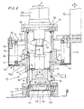
- the device designated by 10 in FIG. 1 is for screwing and unscrewing threaded screw caps 115 into the thread of filler neck 105 of drums, containers or the like. 100, which are provided with bunghole filler or filler neck 105, are provided.
- the device 10 can also be used to screw closure elements provided in a different manner, but with a thread, into barrel filler necks or to unscrew or unscrew them from barrel filler necks.
- a barrel, container or the like. indicated tet the upper cover plate 101 is provided with an opening or the bung 102.
- a filler neck 105 is arranged on the upper drum cover plate 101, the fill opening of which is designated by 106.
- This filler neck 105 is provided with an internal thread 107.
- the circumferential edge 110 delimiting the filling opening 106 has an outer annular edge bead 111, which is provided with a horizontal attachment edge 112 which lies in the plane of the filling opening 106 of the filling nozzle 105 and which is flat.
- This attachment edge 112 merges with the formation of an arcuate section 114 into the filler neck outer wall 113 (FIG. 3).
- the closing of the filling opening 106 of the barrel filler neck 105 takes place in the embodiment shown in FIGS. 1 to 3 by means of a screw cap 115, which consists of plastic or another suitable metallic material and which is provided with a retracted bottom, the circumferential wall portion of the retracted Bottom is provided with an external thread 116 (Fig. 2).
- the screw cap design is such that the screw cap 115 can be screwed with its external thread 116 into the internal thread 107 of the filler neck 105.
- the screw cap 115 has in the interior 117 formed by the retracted bottom 117 on the bottom of the screw cap 115 denoted by 118 engagement or driving elements indicated at 119, eg in the form of wing-like sections.
- engagement or driving elements indicated at 119
- differently designed screw caps or screw plugs can be screwed in and unscrewed with the device 10 if these closure elements are used are provided with an external thread and with engagement and entrainment elements in which the corresponding devices of the device 10 engage in order to be able to turn the closure element about its central axis for screwing in and unscrewing.
- the screw cap screwing and unscrewing device 10 consists of a centering and screwing head 120, an outer centering element 130, a wrench 140 that can be brought into operative connection with the screw cap 115, and a drive device 150 for the wrench.
- a support frame 30 is connected to a vertical support arm 20, which can be moved vertically in the direction of arrow X by means of a drive device, not shown in the drawing, in such a way that it projects laterally from the support arm 20.
- a drive device not shown in the drawing
- the support arm 20 can also be moved in the horizontal direction.
- This support frame 30 is designed as a support bracket 31.
- This support bracket 31 consists of an upper horizontal ring body 32 and a lower horizontal ring body 33 arranged at a distance from the ring body 32 by means of spacer arms 34 and running parallel to the ring body 32, the two central openings of the two ring bodies 32, 33 with 32a, 33a.
- These two openings 32a, 33a of the two ring bodies 32, 33 of the support bracket 31 correspond to one another.
- the diameter of the two openings 32a, 33a of the ring bodies 32, 33 can be the same; however, there is also the possibility of dimensioning the diameter of the opening 32a of the upper ring body 33 somewhat larger than the diameter 33a of the lower ring body 33.
- This support bracket 31 receives the centering and screwing head 120, which - as will be described in more detail below - is pivotally or movably mounted in the support bracket 31 about its longitudinal axis, this centering and screwing head comprising a guide cylinder 40, the outer centering element 130 and the wrench 140, so that in a vertical movement of the support arm 20 with the support bracket 31, the centering and screwing head 120 also takes part in this process.
- the spacer arms 34 which keep the two ring bodies 32, 33 of the support bracket 31 at a distance, are fastened to the outer peripheral region of the two ring bodies 32, 33.
- the outer diameter of the two ring bodies 32, 33 is dimensioned the same.
- the guide cylinder 40 is arranged, which is guided on both sides out of the plane formed by the two ring bodies 32, 33 with a section (FIGS. 1 and 2).
- the upper end of the guide cylinder is designated 40a, its lower end 40b and its interior 40c.
- the guide cylinder 40 Adjacent to its lower end 40b, the guide cylinder 40 has on its outer wall surface a circumferential outer ring 41 which is designed as a support ring for a resilient element.
- the outer ring 41 is an integral part of the guide cylinder 40, which is designed as a cylindrical tube.
- the outer circumference of the outer ring 41 of the guide cylinder 40 is dimensioned such that the outer ring 41 is supported on the inner wall surface of the ring body 33 of the support bracket 31 facing the ring body 32.
- this configuration can be such that the outer circumferential bearing surface of the outer ring 41 is provided with an annular bead with a part-circular section, while the bearing surface for the outer ring 41 on the ring body 33 is provided with a correspondingly profiled annular recess, so that the outer ring 41 can roll off with its bead-like outer profile in the ring groove or groove-shaped recess in the ring body.
- the ring body 33 is designed to be resilient, so that when the ring body 33 is loaded on one side, this loaded section dodges, for example, in the direction of arrow Y, ie the ring body can bend in this area.
- the spacer arms 34 are then also designed to be resilient, so that a change in the position of the annular body 33 in its section loaded by the guide cylinder 40 together with the spacer arms 34 relative to the rigid annular body 32 is possible.
- the storage and mounting of the guide cylinder 40 in the support frame 30 takes place by means of the resilient-elastic element, which in the embodiment shown in FIGS. 1 and 2 is designed as a cylindrical helical compression spring 42 which surrounds the guide cylinder 40 so that it is in the interior of the helical compression spring 42 is arranged.
- the upper end of the helical compression spring 42 is designated 42a and the lower end of the helical compression spring 42b.
- This helical compression spring 42 is clamped between the upper ring body 32 of the support bracket 31 and the outer ring 41 of the guide cylinder 40, in such a way that the helical compression spring 42 with its upper end 40a on the inner wall surface of the upper ring body 32 and with its lower end 42b on the outer ring 41 of the guide cylinder 40.
- the annular body 32 and the outer ring 41 are correspondingly profiled so that lateral deflection of the helical compression spring 42 with its upper end 42a or with its lower end 42b is not possible is.
- the guide cylinder 40 and all the elements connected to it described in greater detail below can be pivoted about the longitudinal axis of the guide cylinder, i.e. the lower end of the guide cylinder 40 in the direction of the arrow X2, for example at 45 in Fig. 2 indicated pivot point pivotable or slidable.
- the guide cylinder 40 carries at its upper end 40a an end plate 46 which is detachably or fixedly connected to the circumferential wall of the guide cylinder 40.
- the drive device 150 for the wrench 140 is arranged on this end plate 46.
- the drive device is designed in a manner known per se as an air motor 50, which is provided with two connections 51, 52 for reversing the direction of rotation of the drive shaft 53 connected to the air motor 50.
- Air-pressure-operated motors are known in a wide variety of embodiments and can be used here as a drive device 150, although drive devices of a different design, such as, for example, electromotive drive devices or the like, are also used. , can be used.
- the drive shaft 53 of the air motor 50 is guided through an opening 47 in the end plate 46 of the guide cylinder 40 and through its interior 40c.
- the bottom free end of the drive shaft 53 carries the wrench 140.
- the drive shaft is variable in length, i.e. the drive shaft is designed so that it is telescopic, which takes place in the direction of arrow X1.
- the drive shaft 53 is under the action of a cylindrical helical compression spring 56 which surrounds the drive shaft 53 in the interior region of the guide cylinder 40 and whose upper end 56a is supported on an upper cylindrical support body 54 and with its lower end 56b on a lower support ring 55, whereby the cylindrical support body 54 and the support ring 55 are arranged at a distance from one another.
- the drive shaft 53 which is formed in two parts in this area, can be moved together by this distance.
- the operation of the helical compression spring 56 will be discussed in more detail below.
- the direction of rotation of the drive shaft 53 is indicated by the arrow X3.
- the outer centering element 130 consists of a cylindrical hollow body 60 which is open on both sides and which is arranged in the interior 40c of the guide cylinder 40 so as to be displaceable in the longitudinal direction.
- the dimensions of the cylindrical hollow body 60 are such that the outer wall surface of the hollow body 60 is guided on the inner wall surface of the guide cylinder 40.
- a stroke limitation for the cylindrical hollow body 60 is indicated, which consists of a pin arranged in the wall of the guide cylinder 40, which extends into the feed path of the cylindrical hollow body 60.
- the outer wall surface of the hollow body 60 is provided with a longitudinal groove 81 into which the Stroke limiting pin engages, at the same time the stroke limiting pin 80 preventing a possible twisting of the cylindrical hollow body 60 about its longitudinal axis.
- This cylindrical hollow body 60 is under the action of a cylindrical helical compression spring 61, which is arranged above the hollow body 60 in the interior 40c of the guide cylinder 40, namely against the inner wall surface of the guide cylinder 40, this helical compression spring 61 having an upper end 61a on an annular Retraction 48 is supported on the upper end 40a of the guide cylinder 40, while the lower end 61b of the helical compression spring 61 is supported on the upper circumferential edge of the cylindrical hollow body 60 (FIGS. 1 and 2).
- the cylindrical hollow body 60 carries a centering ring 62 at its lower end.
- This centering ring 62 can be designed as a special component and the like by means of screw connections. be connected to the hollow body 60.
- the annular inner wall surface 63 of the centering ring 62 widens conically towards the bottom free end 62a, so that the inner wall surface 63 tapers conically upwards (FIGS. 2 to 3).
- This inner wall surface 63 of the centering ring 62 is designed and dimensioned such that when the centering ring 62 is placed on the circumferential edge 110 of the barrel filler neck 105, this circumferential filler neck edge 110 is encompassed or overlapped. Furthermore, the inner wall surface 63 of the centering ring 62 is the configuration of the edge 110 of the filler neck 105 of a barrel, container or the like. 100 replicated.
- the wrench 140 arranged at the free end of the drive shaft 53 is designed such that the wrench 140 can engage in the engagement and driving elements 119 of the screw caps 115, so that when the wrench 140 is turned clockwise or counterclockwise, the screw cap 115 either for the screwing-in process or is taken along for the unscrewing process.
- the connecting piece for the connection of the vacuum generating device is arranged in the wall of the cylindrical hollow body 60 and is designated 90 in FIG. 2.
- the drive shaft 53 carries a horizontal measuring disk 70 for the screw wrench 140 above the wrench 140, the distance from the measuring disk 70 to the lower end of the screw wrench sels 140 corresponds approximately to the length of the wrench 140.
- the outer diameter of the measuring disk 70 which assumes the position shown in FIG. 2, corresponds approximately to the inner diameter of the cylindrical hollow body 60 of the centering element 130, so that when the wrench 140 is lowered or raised, the measuring disk 70 takes part in this movement in the direction of the arrow X6.
- the measuring disk 70 has on its outer circumference a number of recesses which are arranged at equal distances from one another, such as notches, grooves or depressions 71 of a different design.
- a proximity switch 75 is arranged in the path of movement of the measuring disk 70, which is designed in a manner known per se and consists of an amplifier circuit 76, a resonant circuit coil 77 and a shield 78, the line profile of the structure Field is indicated at 79 (Fig. 4).
- This proximity switch 75 is an electronic switching element that indicates whether metal parts have approached a certain distance or not.
- Inductive proximity switches consist of an oscillator that supplies the primary side of a transformer with voltage.
- the metal parts to be detected act as a secondary side. When approaching, an eddy current is induced. This leads to an increase in the primary current, which is registered at a certain threshold. This leads to a change in the output signal.
- An inductive proximity switch can be used if the measuring disk 70 consists of metallic materials. However, if the measuring disk 70 consists of non-metallic materials, such as plastics, then it is advantageous if the circumference of the individual recesses 71 on the base surfaces of the measuring disk 70 plates made of metallic materials are arranged, but then also the peripheral region of the measuring disk 70 must be provided with a metallic coating. Capacitive proximity switches respond when non-metallic materials approach and are used when the measuring disk 70 is not made of metallic materials.
- the proximity switch 75 is arranged in the wall of the cylindrical hollow body 60 in the area adjacent to the centering ring 62. There is also the possibility of arranging the proximity switch 75 in a longitudinally displaceable manner in the wall of the cylindrical hollow body 60, which is advantageous if screw caps 115 of different thickness are to be screwed in or unscrewed.
- the measuring disk 70 in connection with the proximity switch 75 is used in such a way that when the drive device 150 is started up, the drive shaft 53 and thus also the wrench 140 are rotated.
- the measuring disk 70 also lowers slowly and comes into the area of the proximity switch 75, as a result of which Pulses are triggered, which are used for control purposes via corresponding devices, not shown in the drawing.
- Pulses are triggered, which are used for control purposes via corresponding devices, not shown in the drawing.
- a statement is made that the screwing depth has almost been reached.
- the incoming pulses can, for example evaluated in a computer and used to control the screwing depth and screwing torque required. If no more pulses are given, the air motor stops automatically. The screwing torque and thus the final screwing depth is then reached. Monitoring of the screw-in torque is possible in this way.
- the length of the vertical wall section 67 of the inner wall surface 63 of the centering ring 62, which tapers on the inside towards the end, is exactly the screw-in depth of the screw cap 115 or 5 to 10 mm.
- a plurality of helical compression springs which are arranged at the same distance from one another and preferably at a distance from the circumference of the guide cylinder 40, can be provided, the upper ends of which support the upper ring body 32 of the support bracket 31 and with their lower ends on the circumferential outer ring 41 on the outer wall of the guide cylinder, so that these helical compression springs are arranged in a ring around the guide cylinder 40.
- the openings 32a, 33a of the two ring bodies 32, 33 of the support bracket 31 are dimensioned such that the guide cylinder can pivot in the direction of the arrow Y1, Y2, for example at 45, provided that the centering ring 62 is not on the filler neck 105 of a barrel, container or the like. 100 is seated so as not to impair the pivotability in the direction of arrow Y2 on the bottom.
- the screw cap screwing and unscrewing device 10 operates as follows:
- the centering and screwing head 120 of the device 10 is brought into a position above the filler neck 105 by moving the support arm.
- the centering and screwing head 120 is then lowered into the position shown in FIGS. 1 and 2, in which the centering ring 62 with its conical inner wall surface 63 engages over the peripheral edge 110 of the barrel filler neck 105, the conically running inner wall surface 63 engaging the arcuate section 114 of the edge bead 111 of the filler neck 105 comes to rest (FIG. 3).
- This distance H enables the screw cap 115 to be lifted when the screw cap 115 is unscrewed from the thread of the barrel filler neck 105 in such a way that when the centering and screw head 120 is raised further while simultaneously performing a rotary movement of the screw cap 115 by means of the wrench engaging in the screw cap 115 140 when the drive device 150 is started up, the screw cap 115 is unscrewed from the thread of the barrel filler neck 105.
- the vacuum generating device is put into operation, so that a vacuum is generated in the interior of the cylindrical hollow body 60, which holds the screw cap 115 on the wrench 140 or through the sealing surface 68 and the laterally projecting and circumferential wall surface 115a of the screw cap 115 enables (Fig. 3).
- This wrench 140 has a head-like design on the bottom to create a contact surface for the screw cap 115.
- the centering and alignment of the centering and screwing head 120 or the centering ring 62 on the circumferential edge of the barrel filler neck 105 takes place through the interaction of the inner wall surface configuration of the centering ring 62 and the configuration of the circumferential edge 110 of the barrel filling neck 105.
- the centering and screwing head 120 in With respect to its longitudinal axis, which is arranged in the support frame 30 or the support bracket 31 and is spring-loaded, the centering ring 62 is automatically aligned on the barrel filler neck 105, even if this should not assume a vertical position relative to the barrel cover plate 101 of the barrel 100. If the screw cap is lifted from the thread of the barrel filler neck 105, then the centering and screwing Head 120 returned by means of the helical compression spring 42 in its vertical starting position according to Fig.1 and 2. During the unscrewing process of the screw cap 115, the wrench 140 is operatively connected to the screw cap and is rotated by means of the drive device 150 via the drive shaft 53.
- the screw cap 115 falls off and can be transported away. If the centering and screwing head 120 has assumed an inclined position for the unscrewing process, that is to say it has been tilted, then the centering and screwing head is automatically aligned to the vertical by means of the screw compression spring 42. The unscrewing pressure is absorbed by the helical compression spring 56 when the screw cap 115 is raised. When a screw cap 115 is screwed into the thread of a barrel filler neck 105, the helical compression spring 56 presses the wrench down with the screw cap 115 sucked in by vacuum.
- the force of the helical compression spring 56 is dimensioned such that the thread of the screw cap 115 and the internal thread 107 of the barrel filler neck 105 are not damaged.
- the wrench 140 is rotated further in order to ensure that the screw cap 115 is also completely unscrewed from the thread of the barrel filler neck 105, ie the drive of the wrench 140 is maintained until the screw cap 115 has lifted off the barrel filler neck 105.
- the centering and screwing head 120 of the device 10 is moved into the area of the barrel filler neck 105, the cylindrical hollow body 60 with its centering ring 62 by means of the helical compression spring 61 downward in the direction of the barrel filler neck 105 is pressed.
- the centering ring 62 is pressed against the peripheral edge 110 of the barrel filler neck 105.
- the hollow body 60 also lowers with the centering ring 62, the drive shaft 53 then rotating with the wrench 140 when the drive device 150 is started up, the wrench 140 being under the tension of the helical compression spring 56.
- the centering and screwing head 120 adapts to the respective position of the barrel filler neck 105, even if the longitudinal axis of the barrel filler neck 105 does not extend to the vertical.
- the outer centering element 130 is pressed against the barrel filler neck 105, the ring portion 65 of the inner wall surface 63 of the centering ring 62 coming to rest on the attachment edge 112 of the edge bead 111 of the barrel filler neck 105 or being pressed against this annular attachment edge 112.
- the main and the fine alignment of the centering and screwing head 120 then takes place through the interaction of the specially designed contact surface 64 of the inner wall surface 63 of the centering ring 62 with the special design of the peripheral edge 110 of the barrel filler neck 105, and in particular with the attachment edge 112 of the barrel filler neck 105 (Fig.3).
- the lateral alignment of the centering and screwing head 120 then takes place by means of the conically tapering inner wall surface section on the circular section 114 of the circumferential edge 110 of the barrel filler neck 105, while fine-centering and.
- Matching to the filler neck 105 takes place.
- the vertical position to the barrel filler neck 105 is determined and defined by the vertical ring surface 69 of the inner wall 63 of the centering ring 62.
- the wrench 140 which is in engagement with the screw cap 115, is rotated for the screwing-in process, the screwing-in process being carried out in such a way that First of all, there is a short left turn so that the screw cap 115 engages in the beginning of the internal thread 107 of the barrel filler neck 105. Then the direction of rotation of the drive shaft 53 is changed with the wrench 140 and the screw cap 115 is then screwed into the thread of the barrel filler neck 105 by a clockwise rotation.
- the centering and screw head 120 with the drive device 150 is arranged for free movement in the spring 42 or suspended from it.
Landscapes
- Engineering & Computer Science (AREA)
- Mechanical Engineering (AREA)
- Sealing Of Jars (AREA)
- Filling Of Jars Or Cans And Processes For Cleaning And Sealing Jars (AREA)
- Closures For Containers (AREA)
Priority Applications (4)
| Application Number | Priority Date | Filing Date | Title |
|---|---|---|---|
| AT87113912T ATE76613T1 (de) | 1987-09-23 | 1987-09-23 | Vorrichtung zum einschrauben und ausschrauben von schraubkappen od. dgl. in die oder aus den fuellstutzen von faessern, behaeltern u.dgl. |
| EP87113912A EP0308528B1 (fr) | 1987-09-23 | 1987-09-23 | Dispositif pour le vissage et le dévissage de fermetures à vis ou similaires dans ou hors des ajutages de remplissage de fûts, récipients ou similaires |
| DE8787113912T DE3779428D1 (de) | 1987-09-23 | 1987-09-23 | Vorrichtung zum einschrauben und ausschrauben von schraubkappen od. dgl. in die oder aus den fuellstutzen von faessern, behaeltern u.dgl. |
| US07/137,404 US4979350A (en) | 1987-09-09 | 1987-12-23 | Device for the screwing in and the screwing out of screw caps etc. into or out of the filler necks of barrels, containers, etc. |
Applications Claiming Priority (1)
| Application Number | Priority Date | Filing Date | Title |
|---|---|---|---|
| EP87113912A EP0308528B1 (fr) | 1987-09-23 | 1987-09-23 | Dispositif pour le vissage et le dévissage de fermetures à vis ou similaires dans ou hors des ajutages de remplissage de fûts, récipients ou similaires |
Publications (2)
| Publication Number | Publication Date |
|---|---|
| EP0308528A1 true EP0308528A1 (fr) | 1989-03-29 |
| EP0308528B1 EP0308528B1 (fr) | 1992-05-27 |
Family
ID=8197303
Family Applications (1)
| Application Number | Title | Priority Date | Filing Date |
|---|---|---|---|
| EP87113912A Expired - Lifetime EP0308528B1 (fr) | 1987-09-09 | 1987-09-23 | Dispositif pour le vissage et le dévissage de fermetures à vis ou similaires dans ou hors des ajutages de remplissage de fûts, récipients ou similaires |
Country Status (4)
| Country | Link |
|---|---|
| US (1) | US4979350A (fr) |
| EP (1) | EP0308528B1 (fr) |
| AT (1) | ATE76613T1 (fr) |
| DE (1) | DE3779428D1 (fr) |
Families Citing this family (19)
| Publication number | Priority date | Publication date | Assignee | Title |
|---|---|---|---|---|
| US5437139A (en) * | 1991-11-04 | 1995-08-01 | Anderson-Martin Machine Co. | Capping machine head with cap aligning chuck |
| US5687552A (en) * | 1996-03-20 | 1997-11-18 | Abbott Laboratories | Adapter system for a capping machine for applying at least one predetermined axial load |
| DE19628316B4 (de) * | 1996-07-13 | 2006-07-13 | Crystal Growing Systems Gmbh | Vorrichtung zum Heben, Schwenken und Drehen des Deckels eines Vakuumkessels einer Kristallziehanlage |
| US6015062A (en) * | 1997-11-17 | 2000-01-18 | Dayton Systems Group, Inc. | Resealable beverage container and top therefor |
| JP4153572B2 (ja) * | 1997-06-17 | 2008-09-24 | サントリー株式会社 | 圧力容器のフィッティング締付装置 |
| EP1831076B1 (fr) * | 2004-09-02 | 2013-11-06 | Richard Tomalesky | Appareil et procede pour le remplissage sterile de contenants |
| ITTO20060699A1 (it) * | 2006-09-29 | 2008-03-30 | Arol Spa | "testa di chiusura per una macchina tappatrice automatica" |
| US7770358B2 (en) * | 2007-01-17 | 2010-08-10 | Parata Systems, Llc | Devices for capping vials useful in system and method for dispensing prescriptions |
| US7596932B2 (en) * | 2007-01-17 | 2009-10-06 | Parata Systems, Llc | Devices for capping vials useful in system and method for dispensing prescriptions |
| US20100307108A1 (en) * | 2007-01-17 | 2010-12-09 | John Richard Sink | Devices for Capping Vials Useful in System and Method for Dispensing Prescriptions |
| EP2031407B1 (fr) * | 2007-08-29 | 2012-06-06 | F. Hoffmann-La Roche AG | Système de décoiffage |
| US8444130B2 (en) * | 2008-09-30 | 2013-05-21 | Parata Systems, Llc | Devices for capping vials useful in system and method for dispensing prescriptions |
| US10624275B1 (en) * | 2010-03-23 | 2020-04-21 | Myles D. Lewis | Semi-automated crop production system |
| US8413410B2 (en) | 2010-04-30 | 2013-04-09 | Parata Systems, Llc | Devices for capping vials useful in system and method for dispensing prescriptions |
| DE102013103111A1 (de) * | 2013-03-26 | 2014-10-02 | George Robert Collins | Halter für eine Behälteraufnahme und Behälteraufnahme |
| CN106275662B (zh) * | 2016-10-08 | 2018-11-23 | 嵊州市高新技术发展有限公司 | 一种圆柱包装桶夹持机构 |
| IT201800002455A1 (it) * | 2018-02-07 | 2019-08-07 | Dromont S P A | Linea di lavorazione di prodotti fluidi contenuti in contenitori pre dosati. |
| US10807744B1 (en) * | 2018-11-14 | 2020-10-20 | Specialty Equipment Fabrication Company | Apparatus, systems and methods for manipulating a drum or other container |
| CN112744765A (zh) * | 2021-01-13 | 2021-05-04 | 圣灌制药机械设备(苏州)有限公司 | 退盖灌装旋盖系统 |
Citations (3)
| Publication number | Priority date | Publication date | Assignee | Title |
|---|---|---|---|---|
| EP0065180A1 (fr) * | 1981-05-14 | 1982-11-24 | Gerhard Grosskreuz | Dispositif de vissage de bouchons pour fûts |
| GB2121015A (en) * | 1982-06-02 | 1983-12-14 | Hitachi Shipbuilding Eng Co | Opening and closing containers |
| WO1987001091A1 (fr) * | 1985-08-20 | 1987-02-26 | Siegfried Heyng | Dispositif a vis pour le serrage des couvercles de bondes de recipients |
Family Cites Families (6)
| Publication number | Priority date | Publication date | Assignee | Title |
|---|---|---|---|---|
| US2731185A (en) * | 1952-10-31 | 1956-01-17 | California Research Corp | Cap fastener |
| US2983089A (en) * | 1955-08-25 | 1961-05-09 | California Research Corp | Cap fastening machine |
| NL6717745A (fr) * | 1967-12-28 | 1969-07-01 | ||
| GB1359598A (en) * | 1971-03-06 | 1974-07-10 | Ocme Spa | Device for sealing containers having an eccentrically located pouring spout |
| DE2540864C3 (de) * | 1975-09-13 | 1979-08-16 | Foerdertechnik Hamburg Harry Laessig, 2000 Hamburg | Vorrichtung zum Anbringen von Schraubverschlüssen an den Spundlöchern von Fässern |
| US3955341A (en) * | 1975-10-14 | 1976-05-11 | Horix Manufacturing Company | Apparatus for screwing caps on containers |
-
1987
- 1987-09-23 DE DE8787113912T patent/DE3779428D1/de not_active Expired - Lifetime
- 1987-09-23 AT AT87113912T patent/ATE76613T1/de not_active IP Right Cessation
- 1987-09-23 EP EP87113912A patent/EP0308528B1/fr not_active Expired - Lifetime
- 1987-12-23 US US07/137,404 patent/US4979350A/en not_active Expired - Fee Related
Patent Citations (3)
| Publication number | Priority date | Publication date | Assignee | Title |
|---|---|---|---|---|
| EP0065180A1 (fr) * | 1981-05-14 | 1982-11-24 | Gerhard Grosskreuz | Dispositif de vissage de bouchons pour fûts |
| GB2121015A (en) * | 1982-06-02 | 1983-12-14 | Hitachi Shipbuilding Eng Co | Opening and closing containers |
| WO1987001091A1 (fr) * | 1985-08-20 | 1987-02-26 | Siegfried Heyng | Dispositif a vis pour le serrage des couvercles de bondes de recipients |
Also Published As
| Publication number | Publication date |
|---|---|
| US4979350A (en) | 1990-12-25 |
| EP0308528B1 (fr) | 1992-05-27 |
| DE3779428D1 (de) | 1992-07-02 |
| ATE76613T1 (de) | 1992-06-15 |
Similar Documents
| Publication | Publication Date | Title |
|---|---|---|
| EP0308528B1 (fr) | Dispositif pour le vissage et le dévissage de fermetures à vis ou similaires dans ou hors des ajutages de remplissage de fûts, récipients ou similaires | |
| DE3040786C2 (fr) | ||
| DE4029077A1 (de) | Fahrbare muellbehaelter-kombination | |
| EP0425931A1 (fr) | Dispositif de manipulation pour operculer et enlever les opercules des fûts standardisés | |
| DE2514826C3 (de) | Presse, insbesondere zur Vulkanisation von Luftreifen | |
| DE2611950A1 (de) | Fuellstutzen-justiervorrichtung | |
| EP0065180B1 (fr) | Dispositif de vissage de bouchons pour fûts | |
| DE3538971C2 (de) | Vorrichtung zum Aufbringen und/oder Entfernen eines Drehverschlußdeckels auf einen bzw. von einem Behälter | |
| DE2309547A1 (de) | Vorrichtung zum fuellen und leeren von behaeltern, z.b. pipetten | |
| DE602004002178T2 (de) | Füllstutzen mit einem Schraubkopf für Behälter oder Flüssigkeitskreisläufe | |
| EP3529526A1 (fr) | Dispositif de remplissage servant à remplir un réservoir de fluide ainsi que dispositif servant à accoupler le dispositif de remplissage à un conduit de remplissage du réservoir de fluide | |
| DE2540864C3 (de) | Vorrichtung zum Anbringen von Schraubverschlüssen an den Spundlöchern von Fässern | |
| DE4419323A1 (de) | Verfahren und Vorrichtung zum Aufschrauben von Verschlüssen auf Behälter | |
| DE19517542B4 (de) | Vorrichtung zum Verschließen und Öffnen eines Behälters, insbesondere eines Kraftstofftanks | |
| EP0233927A1 (fr) | Dispositif a vis pour le serrage des couvercles de bondes de recipients | |
| DE4444193C1 (de) | Müllsammelsystem | |
| DE2913505C2 (de) | Greifzylinder für Etikettiermaschinen | |
| DE2559390B2 (de) | Kohlefuellwagen | |
| CH687759A5 (de) | Vorrichtung zum Oeffnen und Verschliessen von Drehverschluessen. | |
| DE2228307C2 (de) | Betätigungsvorrichtung für einen Deckel eines Druckgefäßes | |
| DE8114339U1 (de) | Stopfeneinschraubgeraet fuer Faesser | |
| DE8515673U1 (de) | Stopfeneinschraubgerät für Fässer | |
| EP0248228A1 (fr) | Dispositif pour l'amenée automatique et la pose de vis | |
| DE29911943U1 (de) | Flaschengreifer mit Drehvorrichtung | |
| DE102021134069A1 (de) | Transportstern zum Transportieren von Behältern |
Legal Events
| Date | Code | Title | Description |
|---|---|---|---|
| PUAI | Public reference made under article 153(3) epc to a published international application that has entered the european phase |
Free format text: ORIGINAL CODE: 0009012 |
|
| 17P | Request for examination filed |
Effective date: 19880707 |
|
| AK | Designated contracting states |
Kind code of ref document: A1 Designated state(s): AT BE CH DE FR GB LI NL |
|
| 17Q | First examination report despatched |
Effective date: 19901129 |
|
| GRAA | (expected) grant |
Free format text: ORIGINAL CODE: 0009210 |
|
| AK | Designated contracting states |
Kind code of ref document: B1 Designated state(s): AT BE CH DE FR GB LI NL |
|
| PG25 | Lapsed in a contracting state [announced via postgrant information from national office to epo] |
Ref country code: NL Effective date: 19920527 |
|
| REF | Corresponds to: |
Ref document number: 76613 Country of ref document: AT Date of ref document: 19920615 Kind code of ref document: T |
|
| REF | Corresponds to: |
Ref document number: 3779428 Country of ref document: DE Date of ref document: 19920702 |
|
| GBT | Gb: translation of ep patent filed (gb section 77(6)(a)/1977) | ||
| ET | Fr: translation filed | ||
| PG25 | Lapsed in a contracting state [announced via postgrant information from national office to epo] |
Ref country code: GB Effective date: 19920923 Ref country code: AT Effective date: 19920923 |
|
| PG25 | Lapsed in a contracting state [announced via postgrant information from national office to epo] |
Ref country code: LI Effective date: 19920930 Ref country code: CH Effective date: 19920930 Ref country code: BE Effective date: 19920930 |
|
| NLV1 | Nl: lapsed or annulled due to failure to fulfill the requirements of art. 29p and 29m of the patents act | ||
| BERE | Be: lapsed |
Owner name: ARNEMANN GERHARD Effective date: 19920930 |
|
| PLBE | No opposition filed within time limit |
Free format text: ORIGINAL CODE: 0009261 |
|
| STAA | Information on the status of an ep patent application or granted ep patent |
Free format text: STATUS: NO OPPOSITION FILED WITHIN TIME LIMIT |
|
| 26N | No opposition filed | ||
| GBPC | Gb: european patent ceased through non-payment of renewal fee |
Effective date: 19920923 |
|
| PG25 | Lapsed in a contracting state [announced via postgrant information from national office to epo] |
Ref country code: FR Effective date: 19930528 |
|
| REG | Reference to a national code |
Ref country code: CH Ref legal event code: AUV Free format text: DAS OBENGENANNTE PATENT IST, MANGELS BEZAHLUNG DER 6. JAHRESGEBUEHR, GELOESCHT WORDEN. Ref country code: CH Ref legal event code: PL |
|
| REG | Reference to a national code |
Ref country code: FR Ref legal event code: ST |
|
| PGFP | Annual fee paid to national office [announced via postgrant information from national office to epo] |
Ref country code: DE Payment date: 19931123 Year of fee payment: 7 |
|
| PG25 | Lapsed in a contracting state [announced via postgrant information from national office to epo] |
Ref country code: DE Effective date: 19950601 |