EP0065214A2 - Pompe manuelle pour le vidage d'un récipient - Google Patents
Pompe manuelle pour le vidage d'un récipient Download PDFInfo
- Publication number
- EP0065214A2 EP0065214A2 EP82103875A EP82103875A EP0065214A2 EP 0065214 A2 EP0065214 A2 EP 0065214A2 EP 82103875 A EP82103875 A EP 82103875A EP 82103875 A EP82103875 A EP 82103875A EP 0065214 A2 EP0065214 A2 EP 0065214A2
- Authority
- EP
- European Patent Office
- Prior art keywords
- piston
- holder
- force
- annular bead
- container
- Prior art date
- Legal status (The legal status is an assumption and is not a legal conclusion. Google has not performed a legal analysis and makes no representation as to the accuracy of the status listed.)
- Ceased
Links
Images

Classifications
-
- B—PERFORMING OPERATIONS; TRANSPORTING
- B05—SPRAYING OR ATOMISING IN GENERAL; APPLYING FLUENT MATERIALS TO SURFACES, IN GENERAL
- B05B—SPRAYING APPARATUS; ATOMISING APPARATUS; NOZZLES
- B05B11/00—Single-unit hand-held apparatus in which flow of contents is produced by the muscular force of the operator at the moment of use
- B05B11/01—Single-unit hand-held apparatus in which flow of contents is produced by the muscular force of the operator at the moment of use characterised by the means producing the flow
- B05B11/10—Pump arrangements for transferring the contents from the container to a pump chamber by a sucking effect and forcing the contents out through the dispensing nozzle
- B05B11/1042—Components or details
- B05B11/1059—Means for locking a pump or its actuation means in a fixed position
- B05B11/106—Means for locking a pump or its actuation means in a fixed position in a retracted position, e.g. in an end-of-dispensing-stroke position
Definitions
- the invention relates to a manually operated pump for emptying a container, with a first outlet part serving at the same time as an actuating head, a piston which can be actuated by pressing the actuating head against the force of a return spring and which forms a second outlet part connected to the first, with a Piston-receiving housing and a holder for the housing to be fastened to the container, the piston being guided in the holder, the displacement of the pump being connected to the outlet head on the one hand via an outlet channel passing through the piston and having a valve, and on the other hand being connected to an intake port via a valve Piston is locked in a position actuated beyond a predetermined stroke length with the holder.
- the invention has for its object to provide a pump of the generic type, in which the locking device is easier to manufacture and operate without an excessive leakage of the container contents takes place when performing the locking with the pump attached to the container.
- this object is achieved in that the one outlet part has a first annular bead, that the holder has a second annular bead, that at least one of the annular beads is elastically resilient, that the annular beads are directed and dimensioned radially in opposite directions in such a way that they are under elastic mutual displacement can be passed coaxially in both directions and the force exerted on the piston for mutual displacement is greater than the maximum force of the return spring.
- the locking can be effected in a simple manner by pressing the actuating head with a higher force than is required for normal actuation for a desired dispensing of the container contents. This can be done manually with only one hand. If the locking is to be carried out mechanically, a simple axial displacement of the actuating head is sufficient without a predetermined relative position of the parts to be locked having to be maintained before locking. Appropriate positioning means are therefore not required.
- the formation of an annular bead is also simpler than that of a thread, since, in contrast to it, it has no pitch, but lies in a plane perpendicular to the direction of actuation. In the locked position, the ring beads engage behind one another like a snap lock. By pulling the locked parts apart, they can be disengaged just as easily.
- the first annular bead is preferably formed on the actuating head. Here he takes care of the locking. position simultaneously for an additional hold of the actuating head on the piston shaft when the actuating head and the piston shaft are only connected to one another in a snap fit or friction.
- first ring bead can also be formed on the piston, the second ring bead being able to limit the piston guide opening of the holder and both ring beads forming closed rings.
- annular beads With this arrangement and design of the annular beads, they not only enable locking, but also mutual sealing in the area of the pistons guide opening of the holder.
- the first annular bead is formed on the actuating head, at least one of the two annular beads can be formed on a collar which is axially slotted up to the free end within the slotted collar region.
- the slotted collar is particularly flexible, so that the beads can protrude correspondingly far radially, so that they can be easily locked on the one hand and still prevent unwanted unlocking on the other hand.
- the force to be exerted on the piston for the mutual displacement of the annular beads is at least about 50% higher than the maximum return spring force. This ensures sufficient security against unintentional locking during normal operation.
- closure piece of the valve formed in the outlet channel is spring-loaded. This measure ensures a tight seal in any position when the container is full, as long as the piston is not actuated.
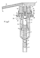
- the pump consists essentially of a piston 1, a housing 2 receiving the piston 1, an actuating head 3 attached to the shaft of the piston 1 protruding from the housing 2, a holder 4 which is attached to the opening edge of a not shown by means of a union nut (not shown)
- Container e.g. a bottle, can, or the like, for a liquid, paste, powder, or similar flowable agent to be sprayed or sprayed.
- the pump has a return spring 5 in the housing 2 between the piston 1 and the bottom of the housing 2, a check valve with a closure piece 6 in the form of a ball in an intake port 7, which opens into the housing 2 and is extended by a flexible dip tube 8 , and a check valve in the outlet channel 9 with a closure piece 10 in the form of a ball, a conical valve seat 11 and a spring 12 which presses the closure piece 10 against the valve seat 11 and which is supported on a securing bushing which is firmly inserted into the shaft bore.
- the outlet channel 9 continues via the socket 13 and the actuating head 3 to the outlet opening 14 at the end of a grommet 15 of the actuating head 3, so that the actuating head 3 simultaneously forms a first outlet part and the piston 1 also forms a second outlet part.
- the actuating head 3 has a cylindrical thin-walled collar 16 or apron.
- the holder 4 is provided with a cylindrical thin-walled collar 17.
- the collar 16 has a radially outwardly directed annular bead 18 and Collar 17 has a radially inwardly directed annular bead 19.
- the piston guide opening of the holder 4 is also delimited by a radially inwardly directed annular bead 20.
- the piston 1 is provided with a radially outwardly directed annular bead 21 in the region of its shaft.
- the collar 17 is provided with slots 22 extending axially up to its free edge and the annular bead 20 on its underside with a conical surface 23 which, like the piston 1, is provided with a conical surface 24 adapted to the surface 23.
- the annular beads 18, 19, 20 and 21 are coaxial and dimensioned such that the annular beads 18, 19 and also the annular beads 20, 21 can be guided past one another with elastic mutual displacement in both axial directions and which for mutual displacement on the piston 1 'over the Actuating head 3 and thus also force to be exerted on the actuating head 3 or by the return spring 5 is greater than the maximum return spring force.
- the annular beads 18 to 21 can thus be brought into the position shown in FIG. 2, in which the annular beads 18, 19 on the one hand and the annular beads 20, 21 on the other hand, so that the actuating head 3 and holder 4 are locked by two pairs of annular beads.
- This locking position is chosen primarily for the transport of the container provided with the pump, in order to prevent the contents of the container from being inadvertently escaped by unintentional pressure or to prevent impact on the actuating head 3.
- the return spring 5 alone is not able to press the piston 1 out of the locking position shown in FIG. 2 into the operating position according to FIG. 1. Rather, this requires an additional pulling by hand on the actuating head 3, which is correspondingly firmly seated on the shaft of the piston 1. 2, the gap between the annular bead 20 and the shaft of the piston 1 is sealed against leakage of the container contents via lateral ventilation openings 25 in the housing 2.
- annular beads 18 and 19 are facilitated by the slots 22 of the collar 17, which ensure sufficient elasticity or flexibility of the collar 17 in order to be able to move the annular beads 18 and 19 past one another for latching or unlatching when they are protrude relatively far radially.
- Corresponding slots can also be provided in addition or only in the collar 16. If necessary, the one or both annular beads 18, 19 are interrupted in the circumferential direction by the slots. In contrast, the annular beads 20 and 21 are continuous to ensure a high sealing effect.
- All parts of the pump except for the balls and springs, are made of elastic plastic, so that the annular beads 20 and 21 due to their inherent elasticity and appropriate dimension when exerting the desired locking and unlocking force can radially displace each other and be moved past each other. If necessary, one or the other pair of annular beads can be omitted, e.g. the pair of annular beads 20, 21 when the container contents are relatively viscous and the diameter of the piston guide opening in the holder 4 is more precisely adapted to the outer diameter of the piston skirt.
Landscapes
- Containers And Packaging Bodies Having A Special Means To Remove Contents (AREA)
- Closures For Containers (AREA)
- Reciprocating Pumps (AREA)
Applications Claiming Priority (2)
| Application Number | Priority Date | Filing Date | Title |
|---|---|---|---|
| DE3118434 | 1981-05-09 | ||
| DE3118434A DE3118434A1 (de) | 1981-05-09 | 1981-05-09 | Handbetaetigte pumpe zum entleeren eines behaelters |
Publications (2)
| Publication Number | Publication Date |
|---|---|
| EP0065214A2 true EP0065214A2 (fr) | 1982-11-24 |
| EP0065214A3 EP0065214A3 (fr) | 1983-01-26 |
Family
ID=6131880
Family Applications (1)
| Application Number | Title | Priority Date | Filing Date |
|---|---|---|---|
| EP82103875A Ceased EP0065214A3 (fr) | 1981-05-09 | 1982-05-05 | Pompe manuelle pour le vidage d'un récipient |
Country Status (5)
| Country | Link |
|---|---|
| EP (1) | EP0065214A3 (fr) |
| JP (1) | JPS5820971A (fr) |
| AU (1) | AU8345382A (fr) |
| DE (1) | DE3118434A1 (fr) |
| ES (1) | ES8303617A1 (fr) |
Cited By (9)
| Publication number | Priority date | Publication date | Assignee | Title |
|---|---|---|---|---|
| GB2122692A (en) * | 1982-05-04 | 1984-01-18 | Sar Spa | Handpump for dispensing fluids |
| US5064102A (en) * | 1989-03-29 | 1991-11-12 | Monturas S.A. | Non-reusable dispensing pump container with reusable dispensing pump |
| EP0498275A1 (fr) * | 1991-02-07 | 1992-08-12 | Tetsuya Tada | Distributeur à pompe et sa valve d'aspiration |
| US5492251A (en) * | 1994-05-27 | 1996-02-20 | Ter S.R.L. | Pressurized liquid dispenser with members for locking it in its lowered position |
| AP594A (en) * | 1994-09-09 | 1997-09-09 | Pumpwell Pty Limited | Fluid pump. |
| EP1023946A2 (fr) | 1999-01-29 | 2000-08-02 | Ter S.R.L. | Distributeur de fluide avec des moyens de bloquage par encliquetage aisément libérables |
| WO2015011593A2 (fr) | 2013-07-25 | 2015-01-29 | Meadwestvaco Calmar S.R.L. | Pompe à actionnement manuel facilité destinée à distribuer des substances fluides |
| CN105422404A (zh) * | 2015-12-16 | 2016-03-23 | 宏光空降装备有限公司 | 单缸高压大油量手摇泵 |
| WO2019119527A1 (fr) * | 2017-12-22 | 2019-06-27 | 浙江晟祺实业有限公司 | Nouvelle tête de pulvérisation |
Families Citing this family (5)
| Publication number | Priority date | Publication date | Assignee | Title |
|---|---|---|---|---|
| US4496082A (en) * | 1981-12-18 | 1985-01-29 | Corsette Douglas Frank | Liquid dispensing pump |
| JPS61238879A (ja) * | 1985-04-16 | 1986-10-24 | Ii D Ee:Kk | 水中粘着剤 |
| JP2540471Y2 (ja) * | 1988-04-14 | 1997-07-02 | 株式会社吉野工業所 | 手動式液体吐出容器のステム付きアクチュエータ |
| JPH0749015Y2 (ja) * | 1988-04-15 | 1995-11-13 | 株式会社吉野工業所 | 手動式液体吐出容器のステム付きアクチュエータ |
| JP7043137B2 (ja) * | 2018-05-30 | 2022-03-29 | 株式会社吉野工業所 | ポンプ |
Family Cites Families (4)
| Publication number | Priority date | Publication date | Assignee | Title |
|---|---|---|---|---|
| US3180534A (en) * | 1963-04-11 | 1965-04-27 | Calmar Inc | Liquid dispenser |
| US3362343A (en) * | 1966-03-01 | 1968-01-09 | Clamar Inc | Liquid dispenser |
| JPS4844402A (fr) * | 1971-10-12 | 1973-06-26 | ||
| GB2062121A (en) * | 1979-10-29 | 1981-05-20 | Dines Plastics Ltd | Lockable pumping device |
-
1981
- 1981-05-09 DE DE3118434A patent/DE3118434A1/de not_active Ceased
-
1982
- 1982-05-05 EP EP82103875A patent/EP0065214A3/fr not_active Ceased
- 1982-05-06 AU AU83453/82A patent/AU8345382A/en not_active Abandoned
- 1982-05-08 ES ES512030A patent/ES8303617A1/es not_active Expired
- 1982-05-10 JP JP57076777A patent/JPS5820971A/ja active Pending
Cited By (11)
| Publication number | Priority date | Publication date | Assignee | Title |
|---|---|---|---|---|
| GB2122692A (en) * | 1982-05-04 | 1984-01-18 | Sar Spa | Handpump for dispensing fluids |
| US5064102A (en) * | 1989-03-29 | 1991-11-12 | Monturas S.A. | Non-reusable dispensing pump container with reusable dispensing pump |
| EP0498275A1 (fr) * | 1991-02-07 | 1992-08-12 | Tetsuya Tada | Distributeur à pompe et sa valve d'aspiration |
| US5492251A (en) * | 1994-05-27 | 1996-02-20 | Ter S.R.L. | Pressurized liquid dispenser with members for locking it in its lowered position |
| EP0686432A3 (fr) * | 1994-05-27 | 1996-06-19 | Ter Srl | Distributeur de liquide sous pression comprenant des éléments pour le verrouiller dans sa position abaissée |
| AP594A (en) * | 1994-09-09 | 1997-09-09 | Pumpwell Pty Limited | Fluid pump. |
| EP1023946A2 (fr) | 1999-01-29 | 2000-08-02 | Ter S.R.L. | Distributeur de fluide avec des moyens de bloquage par encliquetage aisément libérables |
| EP1023946A3 (fr) * | 1999-01-29 | 2003-07-02 | LUMSON S.p.A. | Distributeur de fluide avec des moyens de bloquage par encliquetage aisément libérables |
| WO2015011593A2 (fr) | 2013-07-25 | 2015-01-29 | Meadwestvaco Calmar S.R.L. | Pompe à actionnement manuel facilité destinée à distribuer des substances fluides |
| CN105422404A (zh) * | 2015-12-16 | 2016-03-23 | 宏光空降装备有限公司 | 单缸高压大油量手摇泵 |
| WO2019119527A1 (fr) * | 2017-12-22 | 2019-06-27 | 浙江晟祺实业有限公司 | Nouvelle tête de pulvérisation |
Also Published As
| Publication number | Publication date |
|---|---|
| JPS5820971A (ja) | 1983-02-07 |
| ES512030A0 (es) | 1983-03-01 |
| ES8303617A1 (es) | 1983-03-01 |
| DE3118434A1 (de) | 1982-11-25 |
| AU8345382A (en) | 1982-11-18 |
| EP0065214A3 (fr) | 1983-01-26 |
Similar Documents
| Publication | Publication Date | Title |
|---|---|---|
| EP0254969B1 (fr) | Dispositif pour l'extrusion de matières pâteuses | |
| DE2746517C3 (de) | Spritzeinrichtung | |
| EP0088236B1 (fr) | Distributeur des produits liquides ou pâteux | |
| DE69710321T2 (de) | Ventil, kupplung mit einem solchen ventil, sowie verfahren zum zusammenbau der kupplung | |
| EP0065214A2 (fr) | Pompe manuelle pour le vidage d'un récipient | |
| EP0165949B1 (fr) | Pompe pulverisatrice avec raccord de recipient | |
| DE69731772T2 (de) | Kupplung | |
| DE2824943A1 (de) | Anschlussvorrichtung fuer bremsleitungen | |
| DE2538971A1 (de) | Sprueheinrichtung | |
| DE3425478A1 (de) | Fluessigkeitszerstaeuber | |
| DE3226571A1 (de) | Verbindungsstueck fuer schlauchleitungen von hochdruckreinigungs- und -spruehgeraeten | |
| DE1525103A1 (de) | Gestaengeverbindung,vorzugsweise fuer Scheibenwischergestaenge | |
| DE69118860T2 (de) | Hydraulische selbstregelvorrichtung für kupplungsbetätigungskabel | |
| DE69608847T2 (de) | Schnellkupplung mit einem selbständig belasteten Ventil | |
| EP0505974A1 (fr) | Distributeur de fluides | |
| DE1653402B2 (de) | Auslaßventilanordnung | |
| DE2062910C3 (de) | Kupplungsvorrichtung zum Verbinden eines Gerätes mit einem verdichtetes oder verflüssigtes Gas enthaltenden Behälter | |
| DE8309873U1 (de) | Abgedichteter Gelenkkopf | |
| DE3001687C2 (de) | Verstellbare Düse an einem handbetätigten Flüssigkeitszerstäuber | |
| DE2603566A1 (de) | Kupplung fuer rohre oder schlaeuche | |
| WO1981001696A1 (fr) | Soupape pour reservoir sous pression | |
| DE2851011A1 (de) | Mit ventilen ausgestattete kupplung fuer hochdruck-fluids | |
| DE2221305B2 (de) | Ventileinheitsanordnung für einen unter Druck stehenden Behälter | |
| DE1650869A1 (de) | Hydraulischer Kupplungsverstaerker | |
| DE651327C (de) | Loesbare Kupplung fuer vorzugsweise um ihre Achse frei drehbare Staubsaugerleitungen |
Legal Events
| Date | Code | Title | Description |
|---|---|---|---|
| PUAI | Public reference made under article 153(3) epc to a published international application that has entered the european phase |
Free format text: ORIGINAL CODE: 0009012 |
|
| AK | Designated contracting states |
Designated state(s): FR GB IT NL |
|
| PUAL | Search report despatched |
Free format text: ORIGINAL CODE: 0009013 |
|
| AK | Designated contracting states |
Designated state(s): FR GB IT NL |
|
| 17P | Request for examination filed |
Effective date: 19821223 |
|
| STAA | Information on the status of an ep patent application or granted ep patent |
Free format text: STATUS: THE APPLICATION HAS BEEN REFUSED |
|
| 18R | Application refused |
Effective date: 19840626 |
|
| RIN1 | Information on inventor provided before grant (corrected) |
Inventor name: SCHWAB, EGON Inventor name: PADAR, STEVEN |