EP0065272A2 - Système multiprocesseur - Google Patents
Système multiprocesseur Download PDFInfo
- Publication number
- EP0065272A2 EP0065272A2 EP82104134A EP82104134A EP0065272A2 EP 0065272 A2 EP0065272 A2 EP 0065272A2 EP 82104134 A EP82104134 A EP 82104134A EP 82104134 A EP82104134 A EP 82104134A EP 0065272 A2 EP0065272 A2 EP 0065272A2
- Authority
- EP
- European Patent Office
- Prior art keywords
- bus
- communication bus
- computer system
- control
- lines
- Prior art date
- Legal status (The legal status is an assumption and is not a legal conclusion. Google has not performed a legal analysis and makes no representation as to the accuracy of the status listed.)
- Granted
Links
Images

Classifications
-
- G—PHYSICS
- G06—COMPUTING OR CALCULATING; COUNTING
- G06F—ELECTRIC DIGITAL DATA PROCESSING
- G06F11/00—Error detection; Error correction; Monitoring
- G06F11/36—Prevention of errors by analysis, debugging or testing of software
- G06F11/362—Debugging of software
- G06F11/3648—Debugging of software using additional hardware
- G06F11/3656—Debugging of software using additional hardware using a specific debug interface
-
- G—PHYSICS
- G06—COMPUTING OR CALCULATING; COUNTING
- G06F—ELECTRIC DIGITAL DATA PROCESSING
- G06F11/00—Error detection; Error correction; Monitoring
- G06F11/07—Responding to the occurrence of a fault, e.g. fault tolerance
- G06F11/16—Error detection or correction of the data by redundancy in hardware
-
- G—PHYSICS
- G06—COMPUTING OR CALCULATING; COUNTING
- G06F—ELECTRIC DIGITAL DATA PROCESSING
- G06F13/00—Interconnection of, or transfer of information or other signals between, memories, input/output devices or central processing units
- G06F13/14—Handling requests for interconnection or transfer
- G06F13/36—Handling requests for interconnection or transfer for access to common bus or bus system
- G06F13/362—Handling requests for interconnection or transfer for access to common bus or bus system with centralised access control
- G06F13/364—Handling requests for interconnection or transfer for access to common bus or bus system with centralised access control using independent requests or grants, e.g. using separated request and grant lines
-
- G—PHYSICS
- G06—COMPUTING OR CALCULATING; COUNTING
- G06F—ELECTRIC DIGITAL DATA PROCESSING
- G06F13/00—Interconnection of, or transfer of information or other signals between, memories, input/output devices or central processing units
- G06F13/38—Information transfer, e.g. on bus
- G06F13/42—Bus transfer protocol, e.g. handshake; Synchronisation
- G06F13/4204—Bus transfer protocol, e.g. handshake; Synchronisation on a parallel bus
- G06F13/4208—Bus transfer protocol, e.g. handshake; Synchronisation on a parallel bus being a system bus, e.g. VME bus, Futurebus, Multibus
- G06F13/4217—Bus transfer protocol, e.g. handshake; Synchronisation on a parallel bus being a system bus, e.g. VME bus, Futurebus, Multibus with synchronous protocol
Definitions
- the invention relates to a multi-computer system consisting of an application-related system and a software development system, in particular with a plurality of microcomputers, the system components of which are linked together by a bus line system (communication bus) comprising information lines and control lines and with a central control device connected to the bus line system.
- bus line system communication bus
- Multi-computer systems based on microcomputers the functional sequence of which is controlled centrally, can be used in a wide variety of applications.
- the advantages of such structures are the functional division of hardware and software and the expandability. By improving the hardware, the software portion of the transmission procedures can be reduced and the transmission rate increased.
- the structure of a multi-computer system is largely determined by the communication system, which connects the individual computers to one another and enables data exchange between them.
- a large part of the computer systems uses bus systems of different training and performance.
- the so-called Uni-Bus system works with a common busbar between the computers, through which all communication takes place.
- the advantage of low effort and easy expandability Bus system is opposed by the limited throughput and the total failure when an error occurs in the bus control.
- Such multi-computer systems with an associated bus system are known (Electronics, 1979, A Multi-Microcomputer System at the Workplace, Part 1, Issue 19, Pages 87 to 90, Part 2, Issue 20, Pages 73 to 77).
- the invention has for its object to provide a cost-effective multi-computer system of the type mentioned with high availability and extensibility, in which the effort for software development can be kept as low as possible with good test support and which also enables sufficient fault tolerance.
- the main advantages of separating the application-related system from the software development system are that only one application-related program has to be developed for the computers in the application system, while the support programs in development systems can be reused for many applications.
- the development system computer can also be a commercially available computer and its peripheral equipment can be used in other projects.
- the requirement for the test interface to allow documentation and influencing the program flow without significantly influencing the real-time behavior can be met in a particularly simple manner.
- Such a test interface can be used, for example, to pause or continue the program flow in the application system at specific selectable addresses by the development computer, and to read and modify the entire state of the application system.
- the bus line system (communication bus) in the application system for at least some of its computers can also be equipped with its own private bus, which connects these computers to the memory assigned to them.
- each memory and peripheral unit can remain available in the event of a computer failure if it is also connected to the communication bus.
- Such a structure enables a high throughput for the traffic between each computer and its memory.
- it also allows the components to continue to be used via the communication bus if a private bus fails. For this it is necessary that the entire memory and peripheral traffic of a computer can be handled via the communication bus if necessary.
- the number of control lines in the communication bus is dimensioned with sufficient redundancy to improve the reliability by multiplying this number, and the use of a forward error correction is proposed on the information lines of the communication bus.
- the private bus lines assigned to the communication bus are like this. trained that each is assigned only one computer. This means there are no bus access conflicts. Each computer can access the memory or peripheral unit assigned to it via the private bus and wait until the addressed system component responds. The transfer on the private bus takes place in handshake timing.
- the application system consists of a multi-computer system of, for example, 2 to 10 computers P1, P2 and a number of further system components, for example memories S1.1, S2.1, S2.2, PER peripheral devices.
- the individual system components such as computers, memory and peripheral devices, are linked by a system bus consisting of a communication bus KB and one or more. private bus lines PB is formed.
- a system bus consisting of a communication bus KB and one or more. private bus lines PB is formed.
- the development system ES is used to develop software for the application system.
- the components of the development system ES are essentially a commercial development computer and a number of peripheral devices PB.
- test interface adaptation TA allows documentation and influencing of the program sequence without significantly influencing the real-time behavior.
- This test interface adaptation TA can e.g.
- the program flow in the application system AS is stopped or continued by the development computer ES at certain selectable addresses and the complete one.
- State of the digital fire control system of the AS application system enables the connection of a uniform test interface to the target system. The connection can be made in such a way that no components that are only used for testing and testing remain in the system during use.
- the private bus lines PB provided in the application system AS in addition to the communication bus KB each connect a computer to one or more memories directly associated with it, for example computer P1 and memory S1.1 or computer P2 and memory S2.1, S2.2.
- the simultaneous use of the common line system KB, which is referred to as the communication bus, and the private bus lines PB of the individual application computers enable the structure to be set up without hierarchy Multi-computer systems from different types of application computers.
- the private bus lines, via which a computer, e.g. P1 can access the target computer-specific programs and local data in private memories, e.g. in S1.1, at any time without bus access access conflicts, significantly reduce the risk of overloading the communication bus, especially in large systems.
- the computers and possibly memories are connected to the communication bus KB via bus adaptations TP1, TP2. This enables direct communication between the computers, eg P1 with P2, information exchange via memory connected to the communication bus, eg S1.1, as well as access to shared peripheral devices PER.
- the use of the communication bus KB by several similar computers requires control of the bus access. It is carried out by a central circuit, the arbiter ZA, which controls the transmission to the communication bus in a fixed time frame.
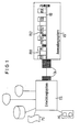
- FIG. 3 An extended four-phase control, in which a line status change of a third line is used, is shown in FIG. 3.
- the line state PH3 of the third line is only changed if the line states PH1 and PH2, which determine the transmission phase, do not change.
- the performance improvements consist, among other things, of the fact that a multi-stage request query and / or a repetition of the request phase can be carried out if there are no requirements. It is also possible to repeat the data phase several times for larger amounts of data. A system component that could only report via the collective line is saved and then identified in a search.
Landscapes
- Engineering & Computer Science (AREA)
- Theoretical Computer Science (AREA)
- Physics & Mathematics (AREA)
- General Engineering & Computer Science (AREA)
- General Physics & Mathematics (AREA)
- Computer Hardware Design (AREA)
- Quality & Reliability (AREA)
- Small-Scale Networks (AREA)
- Multi Processors (AREA)
- Debugging And Monitoring (AREA)
Applications Claiming Priority (2)
| Application Number | Priority Date | Filing Date | Title |
|---|---|---|---|
| DE3119457 | 1981-05-15 | ||
| DE19813119457 DE3119457A1 (de) | 1981-05-15 | 1981-05-15 | Mehrrechnersystem |
Publications (3)
| Publication Number | Publication Date |
|---|---|
| EP0065272A2 true EP0065272A2 (fr) | 1982-11-24 |
| EP0065272A3 EP0065272A3 (en) | 1985-05-15 |
| EP0065272B1 EP0065272B1 (fr) | 1988-08-03 |
Family
ID=6132449
Family Applications (1)
| Application Number | Title | Priority Date | Filing Date |
|---|---|---|---|
| EP82104134A Expired EP0065272B1 (fr) | 1981-05-15 | 1982-05-12 | Système multiprocesseur |
Country Status (2)
| Country | Link |
|---|---|
| EP (1) | EP0065272B1 (fr) |
| DE (1) | DE3119457A1 (fr) |
Cited By (4)
| Publication number | Priority date | Publication date | Assignee | Title |
|---|---|---|---|---|
| EP0065273A3 (fr) * | 1981-05-15 | 1985-04-17 | Siemens Aktiengesellschaft | Système multiprocesseur |
| EP0515812A1 (fr) * | 1991-04-12 | 1992-12-02 | Rockwell International Corporation | Dispositif et procédé pour la développement de logiciel à multiprocesseur |
| WO2003012561A3 (fr) * | 2001-07-30 | 2003-08-21 | Renishaw Plc | Processus de commande de machine-outil et appareil associe |
| EP1731970A2 (fr) | 2005-06-08 | 2006-12-13 | Canon Kabushiki Kaisha | Système d'appareil de contrôle |
Family Cites Families (3)
| Publication number | Priority date | Publication date | Assignee | Title |
|---|---|---|---|---|
| US3657700A (en) * | 1970-07-13 | 1972-04-18 | American Computer Commun | Forward error correcting system |
| DE2729279A1 (de) * | 1977-06-29 | 1979-01-11 | Messerschmitt Boelkow Blohm | Einrichtung zur durchfuehrung des informationsaustausches zwischen digitalbaugruppen |
| DE3119458A1 (de) * | 1981-05-15 | 1982-12-02 | Siemens AG, 1000 Berlin und 8000 München | Mehrrechnersystem |
-
1981
- 1981-05-15 DE DE19813119457 patent/DE3119457A1/de not_active Ceased
-
1982
- 1982-05-12 EP EP82104134A patent/EP0065272B1/fr not_active Expired
Cited By (9)
| Publication number | Priority date | Publication date | Assignee | Title |
|---|---|---|---|---|
| EP0065273A3 (fr) * | 1981-05-15 | 1985-04-17 | Siemens Aktiengesellschaft | Système multiprocesseur |
| EP0515812A1 (fr) * | 1991-04-12 | 1992-12-02 | Rockwell International Corporation | Dispositif et procédé pour la développement de logiciel à multiprocesseur |
| US5956514A (en) * | 1991-04-12 | 1999-09-21 | Boeing North American, Inc. | Apparatus and method for multiple processor software development |
| WO2003012561A3 (fr) * | 2001-07-30 | 2003-08-21 | Renishaw Plc | Processus de commande de machine-outil et appareil associe |
| US6988019B2 (en) | 2001-07-30 | 2006-01-17 | Renishaw Plc | Machine tool control process and apparatus therefor |
| EP1731970A2 (fr) | 2005-06-08 | 2006-12-13 | Canon Kabushiki Kaisha | Système d'appareil de contrôle |
| JP2006343963A (ja) * | 2005-06-08 | 2006-12-21 | Canon Inc | 制御装置 |
| EP1731970A3 (fr) * | 2005-06-08 | 2009-04-01 | Canon Kabushiki Kaisha | Système d'appareil de contrôle |
| US7657670B2 (en) | 2005-06-08 | 2010-02-02 | Canon Kabushiki Kaisha | Control apparatus system |
Also Published As
| Publication number | Publication date |
|---|---|
| DE3119457A1 (de) | 1982-12-09 |
| EP0065272B1 (fr) | 1988-08-03 |
| EP0065272A3 (en) | 1985-05-15 |
Similar Documents
| Publication | Publication Date | Title |
|---|---|---|
| DE2908316C2 (de) | Modular aufgebaute Multiprozessor-Datenverarbeitungsanlage | |
| EP0179936B1 (fr) | Méthode et dispositif pour le contrôle d'un bus en commun | |
| DE102007061437B4 (de) | Bladeserververwaltungssystem | |
| DE2522748C2 (de) | Peripheriekopplungsadapter zur Steuerung der Informationsübertragung zwischen einer Datensammelleitung eines Zentralprozessors und daran angeschlossenen peripheren Einheiten | |
| DE69610157T2 (de) | Ein Ein-/Ausgabeprozessor der gemeinsame Betriebsmittel einem Ein-/Ausgabebus in einem Rechner zur Verfügung stellt | |
| DE68926036T2 (de) | Speicherkonfiguration zur Verwendung für Schnittstellenbildung zwischen einer Systemsteuereinheit für ein Multiprozessorsystem und dem Hauptspeicher | |
| DE69915243T2 (de) | Speicherplattenanordnung-Steuerungsvorrichtung | |
| EP0057756B1 (fr) | Dispositif pour un échange de données dans des systèmes de multi-microcalculateur operant en parallèle | |
| DE3606211A1 (de) | Multiprozessor-computersystem | |
| DE3049774C2 (fr) | ||
| DE69016978T2 (de) | Sicheres Datenschnellschreibverfahren für Massenspeichereinrichtung und ein dieses Verfahren ausführendes Computersystem. | |
| DE3142504A1 (de) | Mehrfachplattenspeicher-uebertragungssystem | |
| EP0065272B1 (fr) | Système multiprocesseur | |
| DE2034423C3 (de) | Verfahren zur Fehlersuche in einem programmgesteuerten Vermittlungssystem | |
| EP1308846B1 (fr) | Dispositif de transfert de données | |
| DE3104903C2 (de) | Anordnung zum Datenaustausch zwischen parallel arbeitenden Mikrorechnern | |
| DD142135A3 (de) | Mehrrechnerkopplung | |
| EP0048869B1 (fr) | Système de multiprocesseur, en particulier comprenant un nombre de microprocesseurs | |
| EP0358785A1 (fr) | Dispositif pour la mise en fonctionnement d'un système multiprocesseur répondant destiné à la commande d'une cabine à signaux électronique dans la technique des signaux de chemin de fer | |
| EP1316891B1 (fr) | Dispositif de transmission de données | |
| EP2901283B1 (fr) | Système informatique, utilisation d'un module de gestion de système et procédé d'échange bidirectionnel de données | |
| EP0562151A1 (fr) | Microprocesseur intégré | |
| DE3221908C2 (de) | Schaltungsanordnung mit mehreren Verarbeitungseinheiten in einem Fernmeldesystem | |
| EP0065273A2 (fr) | Système multiprocesseur | |
| DE3104928C2 (de) | Multi-Mikrorechneranlage mit direktem Speicherzugriff |
Legal Events
| Date | Code | Title | Description |
|---|---|---|---|
| PUAI | Public reference made under article 153(3) epc to a published international application that has entered the european phase |
Free format text: ORIGINAL CODE: 0009012 |
|
| AK | Designated contracting states |
Designated state(s): FR GB IT NL |
|
| 17P | Request for examination filed |
Effective date: 19841219 |
|
| PUAL | Search report despatched |
Free format text: ORIGINAL CODE: 0009013 |
|
| AK | Designated contracting states |
Designated state(s): FR GB IT NL |
|
| 17Q | First examination report despatched |
Effective date: 19870206 |
|
| GRAA | (expected) grant |
Free format text: ORIGINAL CODE: 0009210 |
|
| AK | Designated contracting states |
Kind code of ref document: B1 Designated state(s): FR GB IT NL |
|
| GBT | Gb: translation of ep patent filed (gb section 77(6)(a)/1977) | ||
| ET | Fr: translation filed | ||
| ITF | It: translation for a ep patent filed | ||
| PG25 | Lapsed in a contracting state [announced via postgrant information from national office to epo] |
Ref country code: GB Effective date: 19890512 |
|
| PLBE | No opposition filed within time limit |
Free format text: ORIGINAL CODE: 0009261 |
|
| STAA | Information on the status of an ep patent application or granted ep patent |
Free format text: STATUS: NO OPPOSITION FILED WITHIN TIME LIMIT |
|
| 26N | No opposition filed | ||
| PG25 | Lapsed in a contracting state [announced via postgrant information from national office to epo] |
Ref country code: NL Effective date: 19891201 |
|
| GBPC | Gb: european patent ceased through non-payment of renewal fee | ||
| NLV4 | Nl: lapsed or anulled due to non-payment of the annual fee | ||
| PG25 | Lapsed in a contracting state [announced via postgrant information from national office to epo] |
Ref country code: FR Free format text: LAPSE BECAUSE OF NON-PAYMENT OF DUE FEES Effective date: 19900131 |
|
| REG | Reference to a national code |
Ref country code: FR Ref legal event code: ST |