EP0065482B2 - Cuvette de hanche artificielle - Google Patents
Cuvette de hanche artificielle Download PDFInfo
- Publication number
- EP0065482B2 EP0065482B2 EP82730068A EP82730068A EP0065482B2 EP 0065482 B2 EP0065482 B2 EP 0065482B2 EP 82730068 A EP82730068 A EP 82730068A EP 82730068 A EP82730068 A EP 82730068A EP 0065482 B2 EP0065482 B2 EP 0065482B2
- Authority
- EP
- European Patent Office
- Prior art keywords
- insert
- supporting element
- bone
- thread
- screw
- Prior art date
- Legal status (The legal status is an assumption and is not a legal conclusion. Google has not performed a legal analysis and makes no representation as to the accuracy of the status listed.)
- Expired - Lifetime
Links
- 210000000988 bone and bone Anatomy 0.000 claims abstract description 36
- 238000003801 milling Methods 0.000 claims abstract description 7
- 238000010079 rubber tapping Methods 0.000 claims abstract description 7
- 210000000588 acetabulum Anatomy 0.000 claims abstract description 6
- 238000003780 insertion Methods 0.000 claims description 3
- 230000037431 insertion Effects 0.000 claims description 3
- 238000010276 construction Methods 0.000 claims 1
- 210000002391 femur head Anatomy 0.000 claims 1
- 239000013589 supplement Substances 0.000 claims 1
- 238000013461 design Methods 0.000 description 6
- 230000000694 effects Effects 0.000 description 4
- 238000009412 basement excavation Methods 0.000 description 3
- RTAQQCXQSZGOHL-UHFFFAOYSA-N Titanium Chemical compound [Ti] RTAQQCXQSZGOHL-UHFFFAOYSA-N 0.000 description 2
- 210000004394 hip joint Anatomy 0.000 description 2
- 239000000463 material Substances 0.000 description 2
- 210000003049 pelvic bone Anatomy 0.000 description 2
- 229910052719 titanium Inorganic materials 0.000 description 2
- 239000010936 titanium Substances 0.000 description 2
- 208000006386 Bone Resorption Diseases 0.000 description 1
- 206010058314 Dysplasia Diseases 0.000 description 1
- 238000010521 absorption reaction Methods 0.000 description 1
- 230000001154 acute effect Effects 0.000 description 1
- 230000006978 adaptation Effects 0.000 description 1
- 238000005452 bending Methods 0.000 description 1
- 230000005540 biological transmission Effects 0.000 description 1
- 239000002639 bone cement Substances 0.000 description 1
- 230000024279 bone resorption Effects 0.000 description 1
- 239000012141 concentrate Substances 0.000 description 1
- 238000012937 correction Methods 0.000 description 1
- 230000001419 dependent effect Effects 0.000 description 1
- 238000011161 development Methods 0.000 description 1
- 230000018109 developmental process Effects 0.000 description 1
- 210000002436 femur neck Anatomy 0.000 description 1
- 210000001624 hip Anatomy 0.000 description 1
- 210000001981 hip bone Anatomy 0.000 description 1
- 230000037231 joint health Effects 0.000 description 1
- 238000000034 method Methods 0.000 description 1
- 230000035515 penetration Effects 0.000 description 1
- 238000012545 processing Methods 0.000 description 1
- 239000000126 substance Substances 0.000 description 1
- 238000009827 uniform distribution Methods 0.000 description 1
Images
Classifications
-
- A—HUMAN NECESSITIES
- A61—MEDICAL OR VETERINARY SCIENCE; HYGIENE
- A61F—FILTERS IMPLANTABLE INTO BLOOD VESSELS; PROSTHESES; DEVICES PROVIDING PATENCY TO, OR PREVENTING COLLAPSING OF, TUBULAR STRUCTURES OF THE BODY, e.g. STENTS; ORTHOPAEDIC, NURSING OR CONTRACEPTIVE DEVICES; FOMENTATION; TREATMENT OR PROTECTION OF EYES OR EARS; BANDAGES, DRESSINGS OR ABSORBENT PADS; FIRST-AID KITS
- A61F2/00—Filters implantable into blood vessels; Prostheses, i.e. artificial substitutes or replacements for parts of the body; Appliances for connecting them with the body; Devices providing patency to, or preventing collapsing of, tubular structures of the body, e.g. stents
- A61F2/02—Prostheses implantable into the body
- A61F2/30—Joints
- A61F2/30767—Special external or bone-contacting surface, e.g. coating for improving bone ingrowth
- A61F2/30771—Special external or bone-contacting surface, e.g. coating for improving bone ingrowth applied in original prostheses, e.g. holes or grooves
-
- A—HUMAN NECESSITIES
- A61—MEDICAL OR VETERINARY SCIENCE; HYGIENE
- A61F—FILTERS IMPLANTABLE INTO BLOOD VESSELS; PROSTHESES; DEVICES PROVIDING PATENCY TO, OR PREVENTING COLLAPSING OF, TUBULAR STRUCTURES OF THE BODY, e.g. STENTS; ORTHOPAEDIC, NURSING OR CONTRACEPTIVE DEVICES; FOMENTATION; TREATMENT OR PROTECTION OF EYES OR EARS; BANDAGES, DRESSINGS OR ABSORBENT PADS; FIRST-AID KITS
- A61F2/00—Filters implantable into blood vessels; Prostheses, i.e. artificial substitutes or replacements for parts of the body; Appliances for connecting them with the body; Devices providing patency to, or preventing collapsing of, tubular structures of the body, e.g. stents
- A61F2/02—Prostheses implantable into the body
- A61F2/30—Joints
- A61F2/32—Joints for the hip
- A61F2/34—Acetabular cups
-
- A—HUMAN NECESSITIES
- A61—MEDICAL OR VETERINARY SCIENCE; HYGIENE
- A61F—FILTERS IMPLANTABLE INTO BLOOD VESSELS; PROSTHESES; DEVICES PROVIDING PATENCY TO, OR PREVENTING COLLAPSING OF, TUBULAR STRUCTURES OF THE BODY, e.g. STENTS; ORTHOPAEDIC, NURSING OR CONTRACEPTIVE DEVICES; FOMENTATION; TREATMENT OR PROTECTION OF EYES OR EARS; BANDAGES, DRESSINGS OR ABSORBENT PADS; FIRST-AID KITS
- A61F2/00—Filters implantable into blood vessels; Prostheses, i.e. artificial substitutes or replacements for parts of the body; Appliances for connecting them with the body; Devices providing patency to, or preventing collapsing of, tubular structures of the body, e.g. stents
- A61F2/02—Prostheses implantable into the body
- A61F2/30—Joints
- A61F2/46—Special tools for implanting artificial joints
- A61F2/4603—Special tools for implanting artificial joints for insertion or extraction of endoprosthetic joints or of accessories thereof
- A61F2/4609—Special tools for implanting artificial joints for insertion or extraction of endoprosthetic joints or of accessories thereof of acetabular cups
-
- A—HUMAN NECESSITIES
- A61—MEDICAL OR VETERINARY SCIENCE; HYGIENE
- A61F—FILTERS IMPLANTABLE INTO BLOOD VESSELS; PROSTHESES; DEVICES PROVIDING PATENCY TO, OR PREVENTING COLLAPSING OF, TUBULAR STRUCTURES OF THE BODY, e.g. STENTS; ORTHOPAEDIC, NURSING OR CONTRACEPTIVE DEVICES; FOMENTATION; TREATMENT OR PROTECTION OF EYES OR EARS; BANDAGES, DRESSINGS OR ABSORBENT PADS; FIRST-AID KITS
- A61F2/00—Filters implantable into blood vessels; Prostheses, i.e. artificial substitutes or replacements for parts of the body; Appliances for connecting them with the body; Devices providing patency to, or preventing collapsing of, tubular structures of the body, e.g. stents
- A61F2/02—Prostheses implantable into the body
- A61F2/30—Joints
- A61F2002/30001—Additional features of subject-matter classified in A61F2/28, A61F2/30 and subgroups thereof
- A61F2002/30108—Shapes
- A61F2002/3011—Cross-sections or two-dimensional shapes
- A61F2002/30112—Rounded shapes, e.g. with rounded corners
- A61F2002/30113—Rounded shapes, e.g. with rounded corners circular
- A61F2002/30118—Rounded shapes, e.g. with rounded corners circular concentric circles
-
- A—HUMAN NECESSITIES
- A61—MEDICAL OR VETERINARY SCIENCE; HYGIENE
- A61F—FILTERS IMPLANTABLE INTO BLOOD VESSELS; PROSTHESES; DEVICES PROVIDING PATENCY TO, OR PREVENTING COLLAPSING OF, TUBULAR STRUCTURES OF THE BODY, e.g. STENTS; ORTHOPAEDIC, NURSING OR CONTRACEPTIVE DEVICES; FOMENTATION; TREATMENT OR PROTECTION OF EYES OR EARS; BANDAGES, DRESSINGS OR ABSORBENT PADS; FIRST-AID KITS
- A61F2/00—Filters implantable into blood vessels; Prostheses, i.e. artificial substitutes or replacements for parts of the body; Appliances for connecting them with the body; Devices providing patency to, or preventing collapsing of, tubular structures of the body, e.g. stents
- A61F2/02—Prostheses implantable into the body
- A61F2/30—Joints
- A61F2002/30001—Additional features of subject-matter classified in A61F2/28, A61F2/30 and subgroups thereof
- A61F2002/30316—The prosthesis having different structural features at different locations within the same prosthesis; Connections between prosthetic parts; Special structural features of bone or joint prostheses not otherwise provided for
- A61F2002/30317—The prosthesis having different structural features at different locations within the same prosthesis
- A61F2002/30322—The prosthesis having different structural features at different locations within the same prosthesis differing in surface structures
-
- A—HUMAN NECESSITIES
- A61—MEDICAL OR VETERINARY SCIENCE; HYGIENE
- A61F—FILTERS IMPLANTABLE INTO BLOOD VESSELS; PROSTHESES; DEVICES PROVIDING PATENCY TO, OR PREVENTING COLLAPSING OF, TUBULAR STRUCTURES OF THE BODY, e.g. STENTS; ORTHOPAEDIC, NURSING OR CONTRACEPTIVE DEVICES; FOMENTATION; TREATMENT OR PROTECTION OF EYES OR EARS; BANDAGES, DRESSINGS OR ABSORBENT PADS; FIRST-AID KITS
- A61F2/00—Filters implantable into blood vessels; Prostheses, i.e. artificial substitutes or replacements for parts of the body; Appliances for connecting them with the body; Devices providing patency to, or preventing collapsing of, tubular structures of the body, e.g. stents
- A61F2/02—Prostheses implantable into the body
- A61F2/30—Joints
- A61F2002/30001—Additional features of subject-matter classified in A61F2/28, A61F2/30 and subgroups thereof
- A61F2002/30316—The prosthesis having different structural features at different locations within the same prosthesis; Connections between prosthetic parts; Special structural features of bone or joint prostheses not otherwise provided for
- A61F2002/30317—The prosthesis having different structural features at different locations within the same prosthesis
- A61F2002/30324—The prosthesis having different structural features at different locations within the same prosthesis differing in thickness
-
- A—HUMAN NECESSITIES
- A61—MEDICAL OR VETERINARY SCIENCE; HYGIENE
- A61F—FILTERS IMPLANTABLE INTO BLOOD VESSELS; PROSTHESES; DEVICES PROVIDING PATENCY TO, OR PREVENTING COLLAPSING OF, TUBULAR STRUCTURES OF THE BODY, e.g. STENTS; ORTHOPAEDIC, NURSING OR CONTRACEPTIVE DEVICES; FOMENTATION; TREATMENT OR PROTECTION OF EYES OR EARS; BANDAGES, DRESSINGS OR ABSORBENT PADS; FIRST-AID KITS
- A61F2/00—Filters implantable into blood vessels; Prostheses, i.e. artificial substitutes or replacements for parts of the body; Appliances for connecting them with the body; Devices providing patency to, or preventing collapsing of, tubular structures of the body, e.g. stents
- A61F2/02—Prostheses implantable into the body
- A61F2/30—Joints
- A61F2002/30001—Additional features of subject-matter classified in A61F2/28, A61F2/30 and subgroups thereof
- A61F2002/30316—The prosthesis having different structural features at different locations within the same prosthesis; Connections between prosthetic parts; Special structural features of bone or joint prostheses not otherwise provided for
- A61F2002/30535—Special structural features of bone or joint prostheses not otherwise provided for
- A61F2002/30537—Special structural features of bone or joint prostheses not otherwise provided for adjustable
- A61F2002/30538—Special structural features of bone or joint prostheses not otherwise provided for adjustable for adjusting angular orientation
- A61F2002/3054—Special structural features of bone or joint prostheses not otherwise provided for adjustable for adjusting angular orientation about a connection axis or implantation axis for selecting any one of a plurality of radial orientations between two modular parts, e.g. Morse taper connections, at discrete positions, angular positions or continuous positions
-
- A—HUMAN NECESSITIES
- A61—MEDICAL OR VETERINARY SCIENCE; HYGIENE
- A61F—FILTERS IMPLANTABLE INTO BLOOD VESSELS; PROSTHESES; DEVICES PROVIDING PATENCY TO, OR PREVENTING COLLAPSING OF, TUBULAR STRUCTURES OF THE BODY, e.g. STENTS; ORTHOPAEDIC, NURSING OR CONTRACEPTIVE DEVICES; FOMENTATION; TREATMENT OR PROTECTION OF EYES OR EARS; BANDAGES, DRESSINGS OR ABSORBENT PADS; FIRST-AID KITS
- A61F2/00—Filters implantable into blood vessels; Prostheses, i.e. artificial substitutes or replacements for parts of the body; Appliances for connecting them with the body; Devices providing patency to, or preventing collapsing of, tubular structures of the body, e.g. stents
- A61F2/02—Prostheses implantable into the body
- A61F2/30—Joints
- A61F2/30767—Special external or bone-contacting surface, e.g. coating for improving bone ingrowth
- A61F2/30771—Special external or bone-contacting surface, e.g. coating for improving bone ingrowth applied in original prostheses, e.g. holes or grooves
- A61F2002/3082—Grooves
- A61F2002/30827—Plurality of grooves
-
- A—HUMAN NECESSITIES
- A61—MEDICAL OR VETERINARY SCIENCE; HYGIENE
- A61F—FILTERS IMPLANTABLE INTO BLOOD VESSELS; PROSTHESES; DEVICES PROVIDING PATENCY TO, OR PREVENTING COLLAPSING OF, TUBULAR STRUCTURES OF THE BODY, e.g. STENTS; ORTHOPAEDIC, NURSING OR CONTRACEPTIVE DEVICES; FOMENTATION; TREATMENT OR PROTECTION OF EYES OR EARS; BANDAGES, DRESSINGS OR ABSORBENT PADS; FIRST-AID KITS
- A61F2/00—Filters implantable into blood vessels; Prostheses, i.e. artificial substitutes or replacements for parts of the body; Appliances for connecting them with the body; Devices providing patency to, or preventing collapsing of, tubular structures of the body, e.g. stents
- A61F2/02—Prostheses implantable into the body
- A61F2/30—Joints
- A61F2/30767—Special external or bone-contacting surface, e.g. coating for improving bone ingrowth
- A61F2/30771—Special external or bone-contacting surface, e.g. coating for improving bone ingrowth applied in original prostheses, e.g. holes or grooves
- A61F2002/3085—Special external or bone-contacting surface, e.g. coating for improving bone ingrowth applied in original prostheses, e.g. holes or grooves with a threaded, e.g. self-tapping, bone-engaging surface, e.g. external surface
-
- A—HUMAN NECESSITIES
- A61—MEDICAL OR VETERINARY SCIENCE; HYGIENE
- A61F—FILTERS IMPLANTABLE INTO BLOOD VESSELS; PROSTHESES; DEVICES PROVIDING PATENCY TO, OR PREVENTING COLLAPSING OF, TUBULAR STRUCTURES OF THE BODY, e.g. STENTS; ORTHOPAEDIC, NURSING OR CONTRACEPTIVE DEVICES; FOMENTATION; TREATMENT OR PROTECTION OF EYES OR EARS; BANDAGES, DRESSINGS OR ABSORBENT PADS; FIRST-AID KITS
- A61F2/00—Filters implantable into blood vessels; Prostheses, i.e. artificial substitutes or replacements for parts of the body; Appliances for connecting them with the body; Devices providing patency to, or preventing collapsing of, tubular structures of the body, e.g. stents
- A61F2/02—Prostheses implantable into the body
- A61F2/30—Joints
- A61F2/30767—Special external or bone-contacting surface, e.g. coating for improving bone ingrowth
- A61F2/30771—Special external or bone-contacting surface, e.g. coating for improving bone ingrowth applied in original prostheses, e.g. holes or grooves
- A61F2002/3085—Special external or bone-contacting surface, e.g. coating for improving bone ingrowth applied in original prostheses, e.g. holes or grooves with a threaded, e.g. self-tapping, bone-engaging surface, e.g. external surface
- A61F2002/30858—Threads interrupted by grooves or sidewalls, e.g. flat sidewalls
-
- A—HUMAN NECESSITIES
- A61—MEDICAL OR VETERINARY SCIENCE; HYGIENE
- A61F—FILTERS IMPLANTABLE INTO BLOOD VESSELS; PROSTHESES; DEVICES PROVIDING PATENCY TO, OR PREVENTING COLLAPSING OF, TUBULAR STRUCTURES OF THE BODY, e.g. STENTS; ORTHOPAEDIC, NURSING OR CONTRACEPTIVE DEVICES; FOMENTATION; TREATMENT OR PROTECTION OF EYES OR EARS; BANDAGES, DRESSINGS OR ABSORBENT PADS; FIRST-AID KITS
- A61F2/00—Filters implantable into blood vessels; Prostheses, i.e. artificial substitutes or replacements for parts of the body; Appliances for connecting them with the body; Devices providing patency to, or preventing collapsing of, tubular structures of the body, e.g. stents
- A61F2/02—Prostheses implantable into the body
- A61F2/30—Joints
- A61F2/30767—Special external or bone-contacting surface, e.g. coating for improving bone ingrowth
- A61F2/30771—Special external or bone-contacting surface, e.g. coating for improving bone ingrowth applied in original prostheses, e.g. holes or grooves
- A61F2002/3085—Special external or bone-contacting surface, e.g. coating for improving bone ingrowth applied in original prostheses, e.g. holes or grooves with a threaded, e.g. self-tapping, bone-engaging surface, e.g. external surface
- A61F2002/30861—Special external or bone-contacting surface, e.g. coating for improving bone ingrowth applied in original prostheses, e.g. holes or grooves with a threaded, e.g. self-tapping, bone-engaging surface, e.g. external surface having threads of increasing or decreasing height
-
- A—HUMAN NECESSITIES
- A61—MEDICAL OR VETERINARY SCIENCE; HYGIENE
- A61F—FILTERS IMPLANTABLE INTO BLOOD VESSELS; PROSTHESES; DEVICES PROVIDING PATENCY TO, OR PREVENTING COLLAPSING OF, TUBULAR STRUCTURES OF THE BODY, e.g. STENTS; ORTHOPAEDIC, NURSING OR CONTRACEPTIVE DEVICES; FOMENTATION; TREATMENT OR PROTECTION OF EYES OR EARS; BANDAGES, DRESSINGS OR ABSORBENT PADS; FIRST-AID KITS
- A61F2/00—Filters implantable into blood vessels; Prostheses, i.e. artificial substitutes or replacements for parts of the body; Appliances for connecting them with the body; Devices providing patency to, or preventing collapsing of, tubular structures of the body, e.g. stents
- A61F2/02—Prostheses implantable into the body
- A61F2/30—Joints
- A61F2/30767—Special external or bone-contacting surface, e.g. coating for improving bone ingrowth
- A61F2/30771—Special external or bone-contacting surface, e.g. coating for improving bone ingrowth applied in original prostheses, e.g. holes or grooves
- A61F2002/3085—Special external or bone-contacting surface, e.g. coating for improving bone ingrowth applied in original prostheses, e.g. holes or grooves with a threaded, e.g. self-tapping, bone-engaging surface, e.g. external surface
- A61F2002/30873—Threadings machined on non-cylindrical external surfaces
-
- A—HUMAN NECESSITIES
- A61—MEDICAL OR VETERINARY SCIENCE; HYGIENE
- A61F—FILTERS IMPLANTABLE INTO BLOOD VESSELS; PROSTHESES; DEVICES PROVIDING PATENCY TO, OR PREVENTING COLLAPSING OF, TUBULAR STRUCTURES OF THE BODY, e.g. STENTS; ORTHOPAEDIC, NURSING OR CONTRACEPTIVE DEVICES; FOMENTATION; TREATMENT OR PROTECTION OF EYES OR EARS; BANDAGES, DRESSINGS OR ABSORBENT PADS; FIRST-AID KITS
- A61F2/00—Filters implantable into blood vessels; Prostheses, i.e. artificial substitutes or replacements for parts of the body; Appliances for connecting them with the body; Devices providing patency to, or preventing collapsing of, tubular structures of the body, e.g. stents
- A61F2/02—Prostheses implantable into the body
- A61F2/30—Joints
- A61F2/32—Joints for the hip
- A61F2002/3241—Joints for the hip having a ring, e.g. for locking the femoral head into the acetabular cup
-
- A—HUMAN NECESSITIES
- A61—MEDICAL OR VETERINARY SCIENCE; HYGIENE
- A61F—FILTERS IMPLANTABLE INTO BLOOD VESSELS; PROSTHESES; DEVICES PROVIDING PATENCY TO, OR PREVENTING COLLAPSING OF, TUBULAR STRUCTURES OF THE BODY, e.g. STENTS; ORTHOPAEDIC, NURSING OR CONTRACEPTIVE DEVICES; FOMENTATION; TREATMENT OR PROTECTION OF EYES OR EARS; BANDAGES, DRESSINGS OR ABSORBENT PADS; FIRST-AID KITS
- A61F2/00—Filters implantable into blood vessels; Prostheses, i.e. artificial substitutes or replacements for parts of the body; Appliances for connecting them with the body; Devices providing patency to, or preventing collapsing of, tubular structures of the body, e.g. stents
- A61F2/02—Prostheses implantable into the body
- A61F2/30—Joints
- A61F2/32—Joints for the hip
- A61F2/34—Acetabular cups
- A61F2002/3429—Acetabular cups with an integral peripheral collar or flange, e.g. oriented away from the shell centre line
-
- A—HUMAN NECESSITIES
- A61—MEDICAL OR VETERINARY SCIENCE; HYGIENE
- A61F—FILTERS IMPLANTABLE INTO BLOOD VESSELS; PROSTHESES; DEVICES PROVIDING PATENCY TO, OR PREVENTING COLLAPSING OF, TUBULAR STRUCTURES OF THE BODY, e.g. STENTS; ORTHOPAEDIC, NURSING OR CONTRACEPTIVE DEVICES; FOMENTATION; TREATMENT OR PROTECTION OF EYES OR EARS; BANDAGES, DRESSINGS OR ABSORBENT PADS; FIRST-AID KITS
- A61F2230/00—Geometry of prostheses classified in groups A61F2/00 - A61F2/26 or A61F2/82 or A61F9/00 or A61F11/00 or subgroups thereof
- A61F2230/0002—Two-dimensional shapes, e.g. cross-sections
- A61F2230/0004—Rounded shapes, e.g. with rounded corners
- A61F2230/0006—Rounded shapes, e.g. with rounded corners circular
-
- A—HUMAN NECESSITIES
- A61—MEDICAL OR VETERINARY SCIENCE; HYGIENE
- A61F—FILTERS IMPLANTABLE INTO BLOOD VESSELS; PROSTHESES; DEVICES PROVIDING PATENCY TO, OR PREVENTING COLLAPSING OF, TUBULAR STRUCTURES OF THE BODY, e.g. STENTS; ORTHOPAEDIC, NURSING OR CONTRACEPTIVE DEVICES; FOMENTATION; TREATMENT OR PROTECTION OF EYES OR EARS; BANDAGES, DRESSINGS OR ABSORBENT PADS; FIRST-AID KITS
- A61F2250/00—Special features of prostheses classified in groups A61F2/00 - A61F2/26 or A61F2/82 or A61F9/00 or A61F11/00 or subgroups thereof
- A61F2250/0014—Special features of prostheses classified in groups A61F2/00 - A61F2/26 or A61F2/82 or A61F9/00 or A61F11/00 or subgroups thereof having different values of a given property or geometrical feature, e.g. mechanical property or material property, at different locations within the same prosthesis
- A61F2250/0026—Special features of prostheses classified in groups A61F2/00 - A61F2/26 or A61F2/82 or A61F9/00 or A61F11/00 or subgroups thereof having different values of a given property or geometrical feature, e.g. mechanical property or material property, at different locations within the same prosthesis differing in surface structures
-
- A—HUMAN NECESSITIES
- A61—MEDICAL OR VETERINARY SCIENCE; HYGIENE
- A61F—FILTERS IMPLANTABLE INTO BLOOD VESSELS; PROSTHESES; DEVICES PROVIDING PATENCY TO, OR PREVENTING COLLAPSING OF, TUBULAR STRUCTURES OF THE BODY, e.g. STENTS; ORTHOPAEDIC, NURSING OR CONTRACEPTIVE DEVICES; FOMENTATION; TREATMENT OR PROTECTION OF EYES OR EARS; BANDAGES, DRESSINGS OR ABSORBENT PADS; FIRST-AID KITS
- A61F2250/00—Special features of prostheses classified in groups A61F2/00 - A61F2/26 or A61F2/82 or A61F9/00 or A61F11/00 or subgroups thereof
- A61F2250/0014—Special features of prostheses classified in groups A61F2/00 - A61F2/26 or A61F2/82 or A61F9/00 or A61F11/00 or subgroups thereof having different values of a given property or geometrical feature, e.g. mechanical property or material property, at different locations within the same prosthesis
- A61F2250/0036—Special features of prostheses classified in groups A61F2/00 - A61F2/26 or A61F2/82 or A61F9/00 or A61F11/00 or subgroups thereof having different values of a given property or geometrical feature, e.g. mechanical property or material property, at different locations within the same prosthesis differing in thickness
Definitions
- the invention relates to a support element, which can be screwed into the bone, of an artificial hip socket with an insert, as specified in the preamble of claim 1.
- a support element which can be screwed into the bone, of an artificial hip socket with an insert, as specified in the preamble of claim 1.
- company brochure "LA PROTHESE UNIVERSELLE DE LORD A APPUI TROCHANTERO-DIAPHYSAIRE MADREPORI-QUE" by S. A. Benois Girard & Cie from 1979, such an acetabular cup with a convexly shaped, threaded outer surface is described. After the counter thread has been pre-cut in the acetabulum, this acetabular cup can only be screwed in in a predetermined direction up to a position which has already been achieved by the thread cutter.
- Another support element is known from DE-A-24 11 617, with which an articular surface is snap-in connected, the support ribs here being arranged in a thread shape on an outer surface and the outer surface corresponding to the outer surface of a truncated cone, but the support element is only in one single direction screwdriver, which is determined by the shape of the cut previously made in the bone.
- a carrier element is known from FR-A-20 99 259.
- the ground connection specified in claim 1 is based on the task of creating a carrier element which can be introduced in such a different manner after the finished milling has been made that the surgeon can choose the particularly load-bearing areas of the bone on the one hand and on the other hand a certain orientation of the reference direction of the future Hip joint prosthesis is possible through the direction selected when screwing in the thread.
- the invention is based on the knowledge that the introduction of force into the pelvic bones should take place as far as possible in the direction of the forces which occur when the prosthesis is loaded, which can take place on the one hand through the upper regions of the rounded support element and, in the case of an annular design thereof, via the socket part projecting through the ring.
- the fixation of the socket by threaded segments of the support element concentrates on the cortex area.
- the insertion of the carrier element is simplified in that the thread profile itself generates the necessary counter thread when screwing in, so that prior thread cutting is superfluous.
- a round recess is provided in the carrier element to be screwed into the pelvic bone first, the diameter of which is preferably larger than the height of the remaining ring, the view of the bottom of the milled recess is released, so that when screwing in without additional aids can be easily judged when the carrier element has reached its end position.
- the ring-shaped design is carried out favorably in such a way that the resulting elasticity with respect to deformations of the ring corresponds to that of the bone area surrounding it, so that there is extensive homogeneity of the ring used and the pelvic area and thus the introduction of load forces always takes place over a large area. This also reduces the effects of the notch behavior of the thread and the risk of bone resorption.
- the pan insert has a certain play with respect to the carrier element with regard to its diameter, so that the stress forces that occur can be absorbed largely without deformation of the insert.
- the contact surface insert / support element is perpendicular to the preferred force, i.e. for example, about 45 ° to the screw-in axis, concentrically around it.
- the conical shape has the advantage that the insert sticks against rotation in the ring and that the forces, in particular the axially acting forces, are not only absorbed by a collar of the insert but also by the conical wall of the insert.
- the diameter of the imaginary hemisphere tangent to the thread segments is greater than the corresponding diameter of the regions milled out in the shape of a hemisphere.
- the thread flanks have the shape specified in claim 4, so that when the bone wall is touched for the first time they produce as punctiform contact as possible and penetrate the surface of the knock.
- the rear flank can then have the "clearance angle" necessary for cutting tools.
- This shape of the thread segments is preferably achieved in that the areas of the highest elevations of the thread segments lying behind in the direction of rotation when screwing in are increasingly reduced, which can be done by appropriate removal of the thread segments by rounding or by milling.
- the ring-shaped design has the further advantage that the elasticity of the support element can be largely adapted by choice of material and dimensioning of those of the surrounding bone areas, so that the element does not represent a foreign body with regard to the forces to be transmitted and the force is distributed over as large a surface area as possible.
- the socket to be inserted into the support element which is preferably made of plastic, has a certain amount of play with parts that come into contact with the deformable areas in the support element, the force being introduced from the prosthesis via corresponding stop surfaces to the support element or , in the bones it follows.
- those bone areas which allow maximum force absorption are preferably used for the introduction of force with respect to transverse forces, so that there is an optimal holding effect, while the pressure forces transmitted from the prosthesis through the ring through to the socket bottom and the bottom of the pan is introduced directly into the bone, which does not require a holding effect by a thread or the like.
- the surgeon can, after screwing the element in, select corrections with regard to the later position of the future pivot point of the prosthesis by selecting a specifically suitable insert.
- the desired position of the pivot point and the axial orientation of the recess for receiving the prosthesis head are determined, for example, by means of a suitable sterile measuring device, and a correspondingly selected socket part which has the desired dimensions is used.
- a system of pans adapted to the support element according to the invention accordingly has different heights or radially offset pivot points for the femoral prosthesis part, combinations of the aforementioned sizes to be changed being possible in a single insert part.
- the inclination of the reference axis is aligned by screwing the support element itself in a correspondingly inclined manner, so that no subsequent compensation by the socket part to be used is necessary.
- the ring-shaped carrier element is preferably made of titanium, while the socket inserts are made of plastic. This results in the advantage that the inexpensively producible inserts can easily be kept in stock in various variants, while the support element only has to be held once per bearing on the outside in order to do justice to all occurring cases. Pan insert and support element form a hemispherical insert overall.
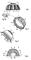
- a number of thread segments 2 arranged at an incline are provided, which are separated from one another by cutting grooves 3.
- the thread segments are sharp-edged on the parts that are led in when they are screwed in and protrude the furthest from the ball surface. In the area of the cutting grooves, they form sharp-edged tips, which are designated 4 by way of example.
- the thread segments are designed to be truncated to flattened to their outer edges, which can be done by parallel processing of the thread segments lying one above the other by means of milling or the like.
- the ring-shaped carrier element is preferably made of titanium, the elasticity properties of which, with a suitable cross-sectional dimensioning, corresponds approximately to those of the surrounding bone material.
- a socket insert 5 is adapted to the inner cross-sectional dimensions of the carrier element 1 and can be inserted into the carrier element already screwed into the bone from below, the upper dome-shaped region 6 of the insert projecting above the carrier element and being inserted inside the bone in the inserted state Recess supports.
- carrier element 1 and insert part 5 are shown separately in a perspective view.
- the two parts have conically shaped regions 7 and 8 which are matched to one another and which may be subject to a certain amount of play. Through this game, the elasticity of the ring can be effective by slightly bending the ring shape. The force is applied via the flanks of the truncated cone 8.
- the insert 5 shown in FIG. 3 has a recess 16 on its underside for receiving the head of the femoral shaft prosthesis. Recesses 17 to 20 on a shoulder 21 together with a nose 22 on the support ring 1 allow different positions of the insert 5.
- a single thread segment 2 is reproduced in FIG. 2a as a detail from FIG. It can be seen that when moving forward in the direction of the arrow for screwing in, the preceding highest area of the segment 2 serves as a cutting tool, while the rear part has a sufficient clearance angle and in this way also reliably prevents the ring from jamming when screwing in.
- the "back" of the thread segment is preferably produced by single or multiple milling, so that a polygonal or rounded structure of the thread segment results accordingly.
- the area leading in when screwing in corresponds to the complete thread profile, while the tracked parts are increasingly reduced in their maximum surface area.
- the parts 1 and 5 can be snapped into one another, a wire ring 9 which engages in a corresponding groove 10 in the carrier element 1 being inserted into a corresponding groove in the insert part.
- Recesses 11 and 12 on the underside of the carrier element serve to receive a screw-in tool, with the uniform distribution of the cut-outs (two of which are not visible) making it possible to conduct precisely while screwing in.
- the dome-shaped area 6 of the insert 5 has a structure 13 which comes into contact with the surface of the knock.
- the inserts are available in different versions, a suitable insert element being selected after screwing in the carrier part 1.
- Suitable depth measuring elements are available for this purpose, which in principle have the shape of the insert shown in FIG. 3, a recess 14 (shown in dashed lines) can additionally be provided in the area of the dome, which allows an assessment when viewed from below through the screwed-in ring 1 whether the dome-shaped area 6 of the insert 5 reaches the bone.
- the recess 14 thus forms a kind of "window".
- the ring 9 is omitted, instead of which markings are preferably provided on the cylindrical region, which mark in relation to the edge between the cylindrical and conical region of the insert 1, which of the several inserts in each case the best Offers seat.
- the annular shape of the carrier element 1 ensures a stable fit of the prosthesis element (without using bone cement) in such a way that the actual cup 5 is held precisely and cannot leave its optimally adjusted position once it has been found.
- the transmission of pressure forces that preferably occur when the prosthesis is loaded takes place for the most part via the dome-shaped area of the insert and for the other part also via the conical attachment, with this being connected to an automatic centering.
- the ring allows a large view of the inner area of the knock recess when screwing in due to its inner opening, so that it can be reliably assessed when the support element 1 is screwed in ben has reached its end position.
- the full load-bearing capacity is only achieved when the thread is fully screwed in and the carrier is flush with the bone cavity.
- FIG. 4 shows an embodiment of an insert with different variants of cutouts (dashed) in section, which belongs to the system according to the invention, with all the inserts in their cylindrical and conical outer area being adapted to the annular carrier 1 shown in the corresponding figures. Due to the different relative position of the recess 16 (versions 22 'and 23 shown in dashed lines), however, the pivot point for the head of the femoral neck prosthesis can be shifted accordingly, so that individual adaptation is possible.
- the dashed version 22 ' enables a different height position with respect to the surface of the knock, while the dashed version 23 is designed for an eccentric receptacle for the prosthesis head.
- the eccentricity can be brought into a suitable direction by rotating the insert, the different latching positions fixing the respectively set position (recesses 17 to 20 in FIG. 3 with nose 22 in FIG. 2).
- bumps are provided on the insert 5 in FIG. 3, which elevations are adapted into the recesses 11, 12 for the socket wrench on the insert 1 in FIG. 2. In this way, rotation of the insert 5 is also ensured if the nose 22 is omitted.
- the recesses 11 and 12 thus have a double function.
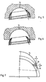
- FIGS. 5 and 6 show the possibility of an inclined screwing into a bone excavation 15 in the sectional representations there. It can be seen that with the self-tapping nature of the thread in connection with the surface which forms part of a ball, different positions can be achieved in the hemispherically milled bone cavity.
- the support element can thus be inserted in accordance with the resilience of the bone and the desired alignment of the prosthesis.
- the outer surface of the annulus corresponds to the surface of a spherical zone.
- FIG. 6 shows schematically how the thread segments of the support element are cut into the recess.
- the radius of the milled recess is smaller than the radius of the hemisphere tangent to the outer edges of the thread segments and the tangents to the relevant radii at the point of contact do not run parallel as with cylindrical or conventional conical threads, they form an acute angle with each other and the two spherical surfaces face each other on the bones increasingly remove from each other, because the threaded segments have a certain slope and the leading part is in an area where the two spherical surfaces do not touch one another, without the measures shown here does not ensure that the threaded segment in the area the cutting groove engages in the bone surface. Rather, the thread segments would initially come into contact with the back of the bone surface and prevent the ring to be screwed into itself. Only the corresponding flattening of the areas of the thread segments lying in the screwing-in direction creates the necessary elevation of the preceding part, so that the cutting edges can preferably engage at points and thus also have the clearance angle necessary for each cutting tool.
- FIG. 7 the conditions for screwing in according to FIG. 6 are shown in an enlarged geometric representation, the two triangles 24 and 25 on the inner circumference representing the front and rear edge of a thread segment whose back is not chamfered or, as shown in FIG. 2a, or is rounded.
- the cut surfaces according to the figure are at different heights, the upper triangle 24 (shown in dashed lines) symbolizing the edge which is advanced when screwing in. If there is a difference in height a as a result of the slope, the leading (cutting) edge is removed from the hemisphere-shaped excavation 15 by the amount b, while the rear surface (lower triangle 25) is in contact.
- the thread segment therefore lies with its back against the bone wall without being able to penetrate like a cutting tool.
- the result is that the carrier element does not cut into the bone wall to produce the thread, but slips or jams there. It can thus be seen how the chamfers made facilitate screwing in without prior thread cutting, in particular if this screwing is to take place in a hemispherical recess with an inclined axis, as shown in FIG. 6.
Landscapes
- Health & Medical Sciences (AREA)
- Orthopedic Medicine & Surgery (AREA)
- Cardiology (AREA)
- Oral & Maxillofacial Surgery (AREA)
- Transplantation (AREA)
- Engineering & Computer Science (AREA)
- Biomedical Technology (AREA)
- Heart & Thoracic Surgery (AREA)
- Vascular Medicine (AREA)
- Life Sciences & Earth Sciences (AREA)
- Animal Behavior & Ethology (AREA)
- General Health & Medical Sciences (AREA)
- Public Health (AREA)
- Veterinary Medicine (AREA)
- Prostheses (AREA)
Claims (10)
Priority Applications (1)
| Application Number | Priority Date | Filing Date | Title |
|---|---|---|---|
| AT82730068T ATE17823T1 (de) | 1981-05-18 | 1982-05-18 | Kuenstliche hueftpfanne. |
Applications Claiming Priority (7)
| Application Number | Priority Date | Filing Date | Title |
|---|---|---|---|
| DE3120148 | 1981-05-18 | ||
| DE3120148 | 1981-05-18 | ||
| DE3147707 | 1981-11-27 | ||
| DE19813147707 DE3147707A1 (de) | 1981-05-18 | 1981-11-27 | Teil einer hueftgelenkprothese |
| EP82730035 | 1982-03-15 | ||
| EP82730035 | 1982-03-15 | ||
| US06/487,185 US4795470A (en) | 1981-05-18 | 1983-04-21 | Two-part socket for hip-joint prosthesis |
Publications (4)
| Publication Number | Publication Date |
|---|---|
| EP0065482A2 EP0065482A2 (fr) | 1982-11-24 |
| EP0065482A3 EP0065482A3 (en) | 1983-01-05 |
| EP0065482B1 EP0065482B1 (fr) | 1986-02-05 |
| EP0065482B2 true EP0065482B2 (fr) | 1990-10-24 |
Family
ID=27432674
Family Applications (1)
| Application Number | Title | Priority Date | Filing Date |
|---|---|---|---|
| EP82730068A Expired - Lifetime EP0065482B2 (fr) | 1981-05-18 | 1982-05-18 | Cuvette de hanche artificielle |
Country Status (4)
| Country | Link |
|---|---|
| US (1) | US4795470A (fr) |
| EP (1) | EP0065482B2 (fr) |
| AT (1) | ATE17823T1 (fr) |
| DE (2) | DE3147707A1 (fr) |
Families Citing this family (67)
| Publication number | Priority date | Publication date | Assignee | Title |
|---|---|---|---|---|
| US4623352A (en) * | 1982-01-18 | 1986-11-18 | Indong Oh | Protrusio cup |
| EP0091315B1 (fr) | 1982-04-07 | 1986-07-30 | National Research Development Corporation | Endoprothèse d'articulation |
| US6042611A (en) * | 1983-03-08 | 2000-03-28 | Joint Medical Products Corporation | Ball and socket bearing for artificial joint |
| US4801301A (en) * | 1983-03-08 | 1989-01-31 | Joint Medical Products Corporation | Ball and socket bearing for artificial joint |
| US4978356A (en) * | 1983-03-08 | 1990-12-18 | Joint Medical Products Corporation | Ball and socket bearing for artificial joint |
| US4960427A (en) * | 1983-03-08 | 1990-10-02 | Joint Medical Products Corporation | Ball and socket bearing for artifical joint |
| US4678472A (en) | 1983-03-08 | 1987-07-07 | Joint Medical Products Corporation | Ball and socket bearing for artificial joint |
| FR2554342A1 (fr) * | 1983-11-09 | 1985-05-10 | Sorem | Perfectionnements apportes aux protheses cotyloidiennes se maintenant d'elles-memes |
| EP0142759A3 (fr) * | 1983-11-22 | 1985-12-27 | Protek AG | Cuvette d'articulation de la hanche |
| CH663894A5 (de) * | 1984-07-16 | 1988-01-29 | Sulzer Ag | Aus einem inneren pfannenkoerper und einer aussenschale bestehende endoprothese fuer eine hueftgelenkspfanne. |
| DE8431422U1 (de) * | 1984-10-23 | 1985-11-21 | Mecron Medizinische Produkte Gmbh, 1000 Berlin | Trägerelement |
| DE8500869U1 (de) * | 1985-01-11 | 1985-12-19 | Mecron Medizinische Produkte Gmbh, 1000 Berlin | Künstliche Hüftpfanne mit einem Tragelement und einem Pfanneneinsatz |
| FR2590478A1 (fr) * | 1985-11-26 | 1987-05-29 | Lahille Michel | Cotyle artificiel |
| FR2591471A1 (fr) * | 1985-12-18 | 1987-06-19 | Bernard Caignan | Perfectionnement aux protheses de la hanche du type a anneau cotyloidien visse. |
| FR2592787B1 (fr) * | 1986-01-10 | 1991-07-12 | Jean Lagrange | Anneau visse a insert retentif |
| CA1290099C (fr) * | 1986-01-21 | 1991-10-08 | Thomas H. Mallory | Articulation artificielle a revetement poreux |
| US4695282A (en) * | 1986-01-23 | 1987-09-22 | Osteonics Corp. | Acetabular cup assembly with selective bearing face orientation |
| CH668901A5 (de) * | 1986-02-18 | 1989-02-15 | Sulzer Ag | Endoprothese fuer eine hueftgelenkspfanne. |
| FR2597329B1 (fr) * | 1986-04-18 | 1988-08-05 | Cuilleron J | Ensemble de refection du cotyle de l'os iliaque destine a recevoir une tete femorale. |
| FR2598609B1 (fr) * | 1986-05-16 | 1988-10-21 | Courtois Serge | Prothese de hanche |
| DE8616344U1 (de) * | 1986-06-18 | 1986-07-31 | Buse, Harry, Prof. Dr.med., 1000 Berlin | Gelenkpfanne für Pfannenimplantate, insbesondere für Hüftgelenkendoprothesen |
| CH670949A5 (fr) * | 1986-09-23 | 1989-07-31 | Sulzer Ag | |
| IT1202437B (it) * | 1987-01-28 | 1989-02-09 | Cremascoli Spa G | Struttura di protesi totale d'anca,comprendente un componenete femorale ed un componente acetabolare,realizzati,entrambi,parte in materiale metallico e parte in materiale ceramico |
| CH671687A5 (fr) * | 1987-03-30 | 1989-09-29 | Sulzer Ag | |
| DE3804310C1 (fr) * | 1988-02-09 | 1989-07-06 | Mecron Medizinische Produkte Gmbh, 1000 Berlin, De | |
| DE8810783U1 (de) * | 1988-06-06 | 1988-10-20 | Mecron Medizinische Produkte Gmbh, 1000 Berlin | Schraubpfanne als Teil einer Hüftgelenksprothese |
| US5217499A (en) * | 1988-08-17 | 1993-06-08 | Minnesota Mining And Manufacturing Company | Rim-bearing acetabular component of hip joint prosthesis |
| GB8819588D0 (en) * | 1988-08-17 | 1988-09-21 | Minnesota Mining & Mfg | Screw-threaded acetabular component of hip joint prosthesis |
| CH675823A5 (fr) * | 1988-08-24 | 1990-11-15 | Sulzer Ag | |
| US4976730A (en) * | 1988-10-11 | 1990-12-11 | Kwan Gett Clifford S | Artificial pericardium |
| US4892549B1 (en) * | 1989-01-31 | 1999-10-05 | Stryker Corp | Dual-radius acetubular cup component |
| US5314491A (en) * | 1990-02-02 | 1994-05-24 | Zimmer, Inc. | Prosthetic socket implant |
| US5049158A (en) * | 1990-04-20 | 1991-09-17 | Boehringer Mannheim Corporation | Acetabular cup assembly |
| DE9014542U1 (de) * | 1990-10-20 | 1991-01-03 | Howmedica GmbH, 2314 Schönkirchen | Schalenelement zur Aufnahme einer Gelenkendoprothese |
| US5443519A (en) * | 1993-04-22 | 1995-08-22 | Implex Corporation | Prosthetic ellipsoidal acetabular cup |
| US5549701A (en) * | 1993-09-20 | 1996-08-27 | Mikhail; W. E. Michael | Acetabular cup |
| US5480448A (en) * | 1993-09-20 | 1996-01-02 | Mikhail; W. E. Michael | Acetabular cup groove insert |
| US20020143402A1 (en) * | 1995-09-04 | 2002-10-03 | Limber Ltd. | Hip joint prostheses |
| US5782928A (en) * | 1995-11-27 | 1998-07-21 | Smith & Nephew, Inc. | Acetabular cup body prosthesis |
| US5676704A (en) * | 1995-11-27 | 1997-10-14 | Smith & Nephew, Inc. | Acetabular cup body prosthesis |
| US5639280A (en) * | 1996-02-02 | 1997-06-17 | Zimmer, Inc. | Constraining ring for a hip cup |
| CA2268735C (fr) * | 1996-10-23 | 2006-03-21 | Michael D. Ries | Prothese de l'acetabulum en forme de cupule |
| US7255712B1 (en) * | 1997-04-15 | 2007-08-14 | Active Implants Corporation | Bone growth promoting implant |
| US6132469A (en) * | 1997-11-07 | 2000-10-17 | Biomet, Inc. | Acetabular liner extractor |
| US6139582A (en) * | 1997-11-21 | 2000-10-31 | Depuy Orthopaedics, Inc. | Acetabular cup with bi-directional steps |
| AU783205C (en) * | 2000-03-15 | 2006-08-17 | Depuy Orthopaedics, Inc. | Prosthetic cup assembly which includes components possessing self-locking taper |
| US7497874B1 (en) | 2001-02-23 | 2009-03-03 | Biomet Manufacturing Corp. | Knee joint prosthesis |
| US20020120340A1 (en) | 2001-02-23 | 2002-08-29 | Metzger Robert G. | Knee joint prosthesis |
| US7326253B2 (en) * | 2001-11-16 | 2008-02-05 | Depuy Products, Inc. | Prosthetic cup assembly having increased assembly congruency |
| WO2003047470A2 (fr) | 2001-12-04 | 2003-06-12 | Discure Ltd. | Implants portant des coussinets pour applications portant une charge |
| DE60327626D1 (de) * | 2002-05-23 | 2009-06-25 | Active Implants Corp | Gelenk- und zahnimplantate |
| US20060226570A1 (en) | 2005-04-12 | 2006-10-12 | Zimmer Technology, Inc. | Method for making a metal-backed acetabular implant |
| US7854768B2 (en) | 2006-01-20 | 2010-12-21 | Zimmer Technology, Inc. | Shoulder arthroplasty system |
| CA2646061C (fr) | 2006-03-20 | 2014-06-17 | Smith & Nephew, Inc. | Assemblage de cupule acetabulaire pour materiaux d'appui multiples |
| US8163028B2 (en) * | 2007-01-10 | 2012-04-24 | Biomet Manufacturing Corp. | Knee joint prosthesis system and method for implantation |
| US8562616B2 (en) | 2007-10-10 | 2013-10-22 | Biomet Manufacturing, Llc | Knee joint prosthesis system and method for implantation |
| US8328873B2 (en) | 2007-01-10 | 2012-12-11 | Biomet Manufacturing Corp. | Knee joint prosthesis system and method for implantation |
| US8157869B2 (en) | 2007-01-10 | 2012-04-17 | Biomet Manufacturing Corp. | Knee joint prosthesis system and method for implantation |
| US8187280B2 (en) | 2007-10-10 | 2012-05-29 | Biomet Manufacturing Corp. | Knee joint prosthesis system and method for implantation |
| US8211184B2 (en) | 2009-04-20 | 2012-07-03 | Michael D. Ries | Acetabular cup |
| US9023112B2 (en) * | 2011-02-24 | 2015-05-05 | Depuy (Ireland) | Maintaining proper mechanics THA |
| US9668745B2 (en) | 2011-12-19 | 2017-06-06 | Depuy Ireland Unlimited Company | Anatomical concentric spheres THA |
| US8858645B2 (en) | 2012-06-21 | 2014-10-14 | DePuy Synthes Products, LLC | Constrained mobile bearing hip assembly |
| CN108836576A (zh) * | 2018-07-18 | 2018-11-20 | 北京爱康宜诚医疗器材有限公司 | 置换假体 |
| EP3685805B1 (fr) | 2019-01-25 | 2021-10-06 | Howmedica Osteonics Corp. | Construction acétabulaire cimentée dotée d'un manchon modulaire verrouillé |
| US12059354B2 (en) * | 2019-02-15 | 2024-08-13 | Howmedica Osteonics Corp. | Robotic acetabulum preparation for acceptance of acetabular cup with engagement features |
| PL74122Y1 (pl) * | 2022-01-26 | 2025-10-13 | Polvet Healthcare Teodorowski Spola Jawna | Panewka endoprotezy stawu biodrowego |
Family Cites Families (15)
| Publication number | Priority date | Publication date | Assignee | Title |
|---|---|---|---|---|
| FR1287526A (fr) * | 1961-01-23 | 1962-03-16 | Prothèse de remplacement de l'articulation coxo-fémorale | |
| US3820167A (en) * | 1968-06-18 | 1974-06-28 | K Sivash | Artificial hip joint |
| DE2129832A1 (de) * | 1970-06-19 | 1971-12-30 | Harris William H | Hueftgelenksprothese und Verfahren zu ihrer Herstellung |
| DE2314708C3 (de) * | 1973-03-24 | 1980-04-10 | Joachim Prof. Dr.Med. 6200 Wiesbaden Eichler | Gelenkpfanne für ein kunstliches Hüftgelenk |
| US3840904A (en) * | 1973-04-30 | 1974-10-15 | R Tronzo | Acetabular cup prosthesis |
| US3818512A (en) * | 1973-05-08 | 1974-06-25 | Y Shersher | Artificial hip-joint with detachable insert |
| FR2295729A1 (fr) * | 1974-12-27 | 1976-07-23 | Mahay Et Cie | Prothese totale de la hanche |
| DE2611985C3 (de) * | 1976-03-20 | 1981-08-13 | Baumann, Friedrich, Prof. Dr.Med., 8858 Neuburg | Hüftkopf-Endoprothese |
| DE2625529A1 (de) * | 1976-06-05 | 1977-12-15 | Sigri Elektrographit Gmbh | Gelenkprothese |
| DE2645101A1 (de) * | 1976-10-04 | 1978-04-06 | Staatliche Porzellan Manufaktu | Hueftgelenk-endoprothesenteil |
| DD236853A3 (de) * | 1978-03-17 | 1986-06-25 | Med Akad | Vollstaendige hueft-gelenk-endoprothese |
| DE2911754A1 (de) * | 1979-03-26 | 1980-10-09 | Hans Dr Reimer | Gelenkpfanne fuer hueftgelenkendoprothesen |
| DE2950536A1 (de) * | 1979-12-15 | 1981-07-02 | Howmedica International, Inc. Zweigniederlassung Kiel, 2300 Kiel | Hueftpfanne |
| CH642840A5 (de) * | 1980-02-08 | 1984-05-15 | Allo Pro Ag | Chirurgisches implantat, insbesondere hueftgelenkpfanne. |
| US4437193A (en) * | 1982-01-18 | 1984-03-20 | Indong Oh | Protrusio cup |
-
1981
- 1981-11-27 DE DE19813147707 patent/DE3147707A1/de not_active Ceased
-
1982
- 1982-05-18 AT AT82730068T patent/ATE17823T1/de not_active IP Right Cessation
- 1982-05-18 EP EP82730068A patent/EP0065482B2/fr not_active Expired - Lifetime
- 1982-05-18 DE DE8282730068T patent/DE3268929D1/de not_active Expired
-
1983
- 1983-04-21 US US06/487,185 patent/US4795470A/en not_active Expired - Lifetime
Also Published As
| Publication number | Publication date |
|---|---|
| EP0065482A2 (fr) | 1982-11-24 |
| ATE17823T1 (de) | 1986-02-15 |
| DE3147707A1 (de) | 1982-12-23 |
| EP0065482A3 (en) | 1983-01-05 |
| DE3268929D1 (en) | 1986-03-20 |
| EP0065482B1 (fr) | 1986-02-05 |
| US4795470A (en) | 1989-01-03 |
Similar Documents
| Publication | Publication Date | Title |
|---|---|---|
| EP0065482B1 (fr) | Cuvette de hanche artificielle | |
| EP0591594B1 (fr) | Anneau d'appui pour coque acétubulaire | |
| EP0222159B1 (fr) | Acétabule pour l'endoprothèse de la hanche | |
| EP0329019B1 (fr) | Coque acétabulaire pour une prothèse d'articulation | |
| DE60013469T2 (de) | Hüftschaft und satz von hüftschäften | |
| DE68918939T2 (de) | Prothese für hüftgelenk. | |
| EP2688517B1 (fr) | Implant à coque acétabulaire | |
| DE102005042766B4 (de) | Plattenloch einer Knochenplatte für die Osteosynthese | |
| DE69717586T2 (de) | Zementfrei verankertes hüftgelenkpfannenimplantat | |
| EP0482320A1 (fr) | Coque acétabulaire pour la réception d'une endoprothèse d'articulation | |
| EP0666068A1 (fr) | Cupule externe d'une coque acétabulaire d'une prothèse de l'articulation de la hanche à au moins deux cupules et prothèse de l'articulation de la hanche avec une telle cupule externe | |
| DE2950536A1 (de) | Hueftpfanne | |
| EP1715815B1 (fr) | Prothese pour un remplacement en surface dans la zone de la sphere d'une enarthrose | |
| EP0150198B1 (fr) | Endoprothese pour cavite cotyloide | |
| DE8500869U1 (de) | Künstliche Hüftpfanne mit einem Tragelement und einem Pfanneneinsatz | |
| CH662267A5 (de) | Kuenstliche gelenkpfanne. | |
| DE3901885A1 (de) | Pfanne fuer eine gelenkendoprothese | |
| EP0318679B2 (fr) | Endoprothèse pour un cotyle de hanche | |
| DE10106863C2 (de) | Implantierbare Pfanne für Hüftgelenk-Endoprothesen | |
| DE68907668T2 (de) | Mit einem Stützringflansch versehenes Acetabularteil einer Hüftgelenksprothese. | |
| EP0179736B1 (fr) | Elément porteur pour cupule de prothèse de la hanche | |
| EP1411869B1 (fr) | Prothese d'articulation artificiel | |
| DE19714050C2 (de) | Hüftpfanne mit Verankerungszapfen | |
| CH677072A5 (en) | Spherical joint for hip joint prosthesis - includes cup shaped half with tapered metal shell carrying cutting thread formed by saw teeth | |
| EP0617931A2 (fr) | Coque acétabulaire artificielle de hanche |
Legal Events
| Date | Code | Title | Description |
|---|---|---|---|
| PUAI | Public reference made under article 153(3) epc to a published international application that has entered the european phase |
Free format text: ORIGINAL CODE: 0009012 |
|
| PUAL | Search report despatched |
Free format text: ORIGINAL CODE: 0009013 |
|
| AK | Designated contracting states |
Designated state(s): AT BE CH DE FR GB IT LI NL SE |
|
| AK | Designated contracting states |
Designated state(s): AT BE CH DE FR GB IT LI NL SE |
|
| 17P | Request for examination filed |
Effective date: 19830628 |
|
| ITF | It: translation for a ep patent filed | ||
| GRAA | (expected) grant |
Free format text: ORIGINAL CODE: 0009210 |
|
| AK | Designated contracting states |
Designated state(s): AT BE CH DE FR GB IT LI NL SE |
|
| REF | Corresponds to: |
Ref document number: 17823 Country of ref document: AT Date of ref document: 19860215 Kind code of ref document: T |
|
| ET | Fr: translation filed | ||
| REF | Corresponds to: |
Ref document number: 3268929 Country of ref document: DE Date of ref document: 19860320 |
|
| PLBI | Opposition filed |
Free format text: ORIGINAL CODE: 0009260 |
|
| 26 | Opposition filed |
Opponent name: IMPLANT MEDIZINTECHNIK GMBH & CO. BETRIEBS KG Effective date: 19861105 Opponent name: AESCULAP-WERKE AG VORMALS JETTER & SCHEERER Effective date: 19861105 |
|
| NLR1 | Nl: opposition has been filed with the epo |
Opponent name: IMPLANT MEDIZINTECHNIK GMBH & CO. BETRIEBS KG Opponent name: AESCULAP-WERKE AG VORMALS JETTER & SCHEERER |
|
| PUAH | Patent maintained in amended form |
Free format text: ORIGINAL CODE: 0009272 |
|
| STAA | Information on the status of an ep patent application or granted ep patent |
Free format text: STATUS: PATENT MAINTAINED AS AMENDED |
|
| ITF | It: translation for a ep patent filed | ||
| 27A | Patent maintained in amended form |
Effective date: 19901024 |
|
| AK | Designated contracting states |
Kind code of ref document: B2 Designated state(s): AT BE CH DE FR GB IT LI NL SE |
|
| ET3 | Fr: translation filed ** decision concerning opposition | ||
| NLR2 | Nl: decision of opposition | ||
| NLR3 | Nl: receipt of modified translations in the netherlands language after an opposition procedure | ||
| ITTA | It: last paid annual fee | ||
| ITPR | It: changes in ownership of a european patent |
Owner name: CAMBIO SEDE;MECRON MEDIZINISCHE PRODUKTE GMBH |
|
| REG | Reference to a national code |
Ref country code: CH Ref legal event code: PFA Free format text: JOHNSON & JOHNSON PROFESSIONAL PRODUCTS GMBH |
|
| REG | Reference to a national code |
Ref country code: FR Ref legal event code: CD Ref country code: FR Ref legal event code: CA |
|
| NLT1 | Nl: modifications of names registered in virtue of documents presented to the patent office pursuant to art. 16 a, paragraph 1 |
Owner name: JOHNSON & JOHNSON PROFESSIONAL PRODUCTS GMBH TE NO |
|
| EAL | Se: european patent in force in sweden |
Ref document number: 82730068.2 |
|
| REG | Reference to a national code |
Ref country code: CH Ref legal event code: PUE Owner name: JOHNSON & JOHNSON PROFESSIONAL PRODUCTS GMBH -DANN |
|
| NLS | Nl: assignments of ep-patents |
Owner name: JOHNSON & JOHNSON MEDICAL GMBH;JOHNSON & JOHNSON G |
|
| BECA | Be: change of holder's address |
Free format text: 960917 *JOHNSON & JOHNSON MEDICAL G.M.H.B.:OSTSTR. 1, D-22844 NORDERSTEDT |
|
| BECH | Be: change of holder |
Free format text: 960917 *JOHNSON & JOHNSON MEDICAL G.M.H.B.:OSTSTR. 1, D-22844 NORDERSTEDT |
|
| REG | Reference to a national code |
Ref country code: GB Ref legal event code: 732E |
|
| PGFP | Annual fee paid to national office [announced via postgrant information from national office to epo] |
Ref country code: DE Payment date: 19970523 Year of fee payment: 16 |
|
| PG25 | Lapsed in a contracting state [announced via postgrant information from national office to epo] |
Ref country code: DE Free format text: THE PATENT HAS BEEN ANNULLED BY A DECISION OF A NATIONAL AUTHORITY Effective date: 19980513 |
|
| PGFP | Annual fee paid to national office [announced via postgrant information from national office to epo] |
Ref country code: SE Payment date: 20010417 Year of fee payment: 20 |
|
| PGFP | Annual fee paid to national office [announced via postgrant information from national office to epo] |
Ref country code: CH Payment date: 20010511 Year of fee payment: 20 |
|
| PGFP | Annual fee paid to national office [announced via postgrant information from national office to epo] |
Ref country code: AT Payment date: 20010514 Year of fee payment: 20 |
|
| PGFP | Annual fee paid to national office [announced via postgrant information from national office to epo] |
Ref country code: GB Payment date: 20010516 Year of fee payment: 20 |
|
| PGFP | Annual fee paid to national office [announced via postgrant information from national office to epo] |
Ref country code: FR Payment date: 20010518 Year of fee payment: 20 |
|
| PGFP | Annual fee paid to national office [announced via postgrant information from national office to epo] |
Ref country code: NL Payment date: 20010531 Year of fee payment: 20 |
|
| PGFP | Annual fee paid to national office [announced via postgrant information from national office to epo] |
Ref country code: BE Payment date: 20010717 Year of fee payment: 20 |
|
| BE20 | Be: patent expired |
Free format text: 20020518 *JOHNSON & JOHNSON MEDICAL G.M.H.B. |
|
| REG | Reference to a national code |
Ref country code: GB Ref legal event code: IF02 |
|
| PG25 | Lapsed in a contracting state [announced via postgrant information from national office to epo] |
Ref country code: LI Free format text: LAPSE BECAUSE OF EXPIRATION OF PROTECTION Effective date: 20020517 Ref country code: GB Free format text: LAPSE BECAUSE OF EXPIRATION OF PROTECTION Effective date: 20020517 Ref country code: CH Free format text: LAPSE BECAUSE OF EXPIRATION OF PROTECTION Effective date: 20020517 |
|
| PG25 | Lapsed in a contracting state [announced via postgrant information from national office to epo] |
Ref country code: NL Free format text: LAPSE BECAUSE OF EXPIRATION OF PROTECTION Effective date: 20020518 Ref country code: AT Free format text: LAPSE BECAUSE OF EXPIRATION OF PROTECTION Effective date: 20020518 |
|
| REG | Reference to a national code |
Ref country code: GB Ref legal event code: PE20 Effective date: 20020517 |
|
| REG | Reference to a national code |
Ref country code: CH Ref legal event code: PL |
|
| NLV7 | Nl: ceased due to reaching the maximum lifetime of a patent |
Effective date: 20020518 |
|
| EUG | Se: european patent has lapsed |
Ref document number: 82730068.2 |
|
| APAH | Appeal reference modified |
Free format text: ORIGINAL CODE: EPIDOSCREFNO |