EP0065522B1 - Turbine dentaire - Google Patents
Turbine dentaire Download PDFInfo
- Publication number
- EP0065522B1 EP0065522B1 EP81902684A EP81902684A EP0065522B1 EP 0065522 B1 EP0065522 B1 EP 0065522B1 EP 81902684 A EP81902684 A EP 81902684A EP 81902684 A EP81902684 A EP 81902684A EP 0065522 B1 EP0065522 B1 EP 0065522B1
- Authority
- EP
- European Patent Office
- Prior art keywords
- turbine
- bore
- rotor
- wall
- nose
- Prior art date
- Legal status (The legal status is an assumption and is not a legal conclusion. Google has not performed a legal analysis and makes no representation as to the accuracy of the status listed.)
- Expired
Links
- 230000001681 protective effect Effects 0.000 claims description 12
- 239000000725 suspension Substances 0.000 claims description 6
- 239000002699 waste material Substances 0.000 description 7
- 239000000463 material Substances 0.000 description 3
- 239000008280 blood Substances 0.000 description 1
- 210000004369 blood Anatomy 0.000 description 1
- 210000003298 dental enamel Anatomy 0.000 description 1
- 210000004268 dentin Anatomy 0.000 description 1
- 238000006073 displacement reaction Methods 0.000 description 1
- 239000000428 dust Substances 0.000 description 1
- 230000000694 effects Effects 0.000 description 1
- 210000000056 organ Anatomy 0.000 description 1
- 238000007789 sealing Methods 0.000 description 1
- 230000001256 tonic effect Effects 0.000 description 1
Images
Classifications
-
- A—HUMAN NECESSITIES
- A61—MEDICAL OR VETERINARY SCIENCE; HYGIENE
- A61C—DENTISTRY; APPARATUS OR METHODS FOR ORAL OR DENTAL HYGIENE
- A61C1/00—Dental machines for boring or cutting ; General features of dental machines or apparatus, e.g. hand-piece design
- A61C1/08—Machine parts specially adapted for dentistry
-
- A—HUMAN NECESSITIES
- A61—MEDICAL OR VETERINARY SCIENCE; HYGIENE
- A61C—DENTISTRY; APPARATUS OR METHODS FOR ORAL OR DENTAL HYGIENE
- A61C1/00—Dental machines for boring or cutting ; General features of dental machines or apparatus, e.g. hand-piece design
- A61C1/08—Machine parts specially adapted for dentistry
- A61C1/16—Protecting caps for hand-pieces or angle-pieces
Definitions
- the invention relates to a dental turbine.
- the rotor housed in the head of an air turbine for dental burs consists of a shaft which can be mounted on ball bearings or air bearings.
- the axis has a housing in which is located the fixing mechanism of the cutter. It extends outward through a bore provided in the nose of the turbine.
- the rotor In the head of the turbine, the rotor is itself mounted on rings made of flexible material or O-rings which in particular ensure its radial suspension. This means that the rotor is liable to undergo radial displacements depending on the pressure exerted on the head of the turbine. It is therefore necessary that the diameter of the bore provided in the turbine nose is sufficiently larger than the diameter of the axis in order to prevent the latter, when it rotates, from abutting and rubbing against the bore wall. There is therefore a space between the axis and the bore provided in the nose of the turbine through which dentin, enamel dust, blood, sealing residues and other waste can infiltrate when the turbine is in action.
- the present invention relates to the production of a dental turbine with ball bearings or with one or more air bearings, designed in such a way that waste of all kinds capable of seeping into it by the route described above is prevented reach the vital organs of the rotor, that is to say the bearing or the air bearing located on the side of the turbine nose as well as the air intake ducts.
- the dental turbine according to the invention comprises a protective sleeve in one piece composed of a first cylindrical part fitted on the outer wall of the bearing located on the side of the nose of the turbine, of a second part extending the first radially towards the axis of the rotor so as to cover the radial face of the bearing facing the bore of the turbine nose and of a third cylindrical part which extends the second axially along said axis of the rotor as far as the radial space provided between that -this and the bore.
- the bearing suspension ring which is enveloped by the sleeve is mounted around the first cylindrical part thereof.
- a ring of flexible material is compressed between the outer wall of the third cylindrical part of the protective sleeve and the inner wall of the head of the turbine.
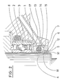
- the protective sleeve 1 which is in one piece consists of a first cylindrical part 9, an intermediate part 17 and a second cylindrical part 14. Its first cylindrical part 9 is adjusted to the outer ring 2 of a ball bearing.
- the protective sleeve 1 is extended, by its intermediate part 17, radially towards the axis 4 of the rotor so as to cover the radial face of the bearing facing the bore 6 of the nose 7 of the turbine and then, by its second part cylindrical 14, axially along the axis 4 as far as the radial space 5 existing between the latter and the wall of the bore 6 provided in the nose 7 of the turbine.
- a sufficient radial space 12 must be provided between the outer wall of the second cylindrical part 14 of the protective sleeve 1 and the bore 6 made in the nose 7 of the turbine.
- waste of all kinds can penetrate into it, either through the radial space 10 between the axis 4 and the inner wall of the second cylindrical part 14 of the protective sleeve 1, or through the radial space 12 between the outer wall of the second cylindrical part 14 of the protective sleeve 1 and the bore 6 made in the nose 7 of the turbine.
- the space 10 is infinitely small and hardly lends itself to the passage of waste.
- the rotary movement of axis 4 tends to eliminate the waste that could have infiltrated through said space 10.
- the waste which could penetrate inside the turbine through the space 12 will accumulate in the housing 18 comprised between the internal wall 15 of the head of the turbine and the outer wall of the second cylindrical part 14 of the protective sleeve 1 where they will be contained by a ring of flexible material 13 compressed in the housing 18.
Landscapes
- Health & Medical Sciences (AREA)
- Oral & Maxillofacial Surgery (AREA)
- Dentistry (AREA)
- Epidemiology (AREA)
- Life Sciences & Earth Sciences (AREA)
- Animal Behavior & Ethology (AREA)
- General Health & Medical Sciences (AREA)
- Public Health (AREA)
- Veterinary Medicine (AREA)
- Dental Tools And Instruments Or Auxiliary Dental Instruments (AREA)
Description
- L'invention concerne une turbine dentaire.
- Le rotor logé dans la tête d'une turbine à air pour fraises dentaires est constitué d'un axe qui peut être monté sur des roulements à billes ou des paliers à air. L'axe comporte un logement dans lequel est situé le mécanisme de fixation de la fraise. Il se prolonge vers l'extérieur en traversant un alésage prévu dans le nez de la turbine.
- Dans la tête de la turbine, le rotor est lui- même monté sur des anneaux en matière souple ou des bagues toriques qui en assurent la suspension radiale notamment. Cela signifie que le rotor est susceptible de subir des déplacements radiaux suivant la pression exercée sur la tête de la turbine. Il est dès lors nécessaire que le diamètre de l'alésage prévu dans le nez de la turbine soit suffisamment plus grand que le diamètre de l'axe afin d'éviter que celui-ci, lorsqu'il tourne, vienne buter et frotter contre la paroi de l'alésage. Un espace existe donc entre l'axe et l'alésage prévu dans le nez de la turbine par lequel de la dentine, de la poussière d'émail, du sang, des résidus de plombage et d'autres déchets peuvent s'infiltrer lorsque la turbine est en action. Ces déchets sont propulsés jusqu'à la hauteur du palier situé du côté du nez de la turbine et des conduits d'arrivée d'air qu'ils viennent encrasser et obstruer. La fiabilité des turbines dentaires répondant aux caractéristiques prédé- crites se trouve ainsi mise en péril. Leur palier situé du côté du nez de la turbine et les conduits d'arrivée d'air doivent être régulièrement nettoyés, voire remplacés.
- La présente invention vise la réalisation d'une turbine dentaire à roulements à billes ou à un ou plusieurs paliers à air, conçue de telle façon que les déchets de toutes sortes susceptibles de s'infiltrer en elle par la voie décrite ci-dessus soient empêchés d'atteindre les organes vitaux du rotor, c'est-à-dire le roulement ou le palier à air situé du côté du nez de la turbine ainsi que les conduits d'arrivée d'air.
- La turbine dentaire selon l'invention comporte une douille de protection en une seule pièce composée d'une première partie cylindrique ajustée sur la paroi extérieure du palier situé du côté du nez de la turbine, d'une seconde partie prolongeant la première radialement vers l'axe du rotor de manière à recouvrir la face radiale du palier tournée vers l'alésage du nez de turbine et d'une troisième partie cylindrique qui prolonge la seconde axialement le long du dit axe du rotor jusque dans l'espace radial prévu entre celui-ci et l'alésage. De plus, l'anneau de suspension du palier qui est enveloppé par la douille est monté autour de la première partie cylindrique de celle-ci.
- De préférence, un anneau en matière souple est comprimé entre la paroi extérieure de la troisième partie cylindrique de la douille de protection et la paroi intérieure de la tête de la turbine.
- Les dessins annexés représentent, à titre d'exemple, une forme d'exécution possible de -l'invention.
- La fig. 1 est une vue en coupe transversale de la tête de la turbine.
- La fig. 2 est une vue partielle de la fig. 1.
- La douille de protection 1 qui est d'une seule pièce se compose d'une première partie cylin- dique 9, d'une partie intermédiaire 17 et d'une seconde partie cylindrique 14. Sa première partie cylindrique 9 est ajustée sur la bague extérieure 2 d'un roulement à billes. La douille 1 de protection se prolonge, par sa partie intermédiaire 17, radialement vers l'axe 4 du rotor de 'manière à recouvrir la face radiale du roulement tournée vers l'alésage 6 du nez 7 de la turbine puis, par sa seconde partie cylindrique 14, axialement le long de l'axe 4 jusque dans l'espace radial 5 existant entre ce dernier et la paroi de l'alésage 6 prévu dans le nez 7 de la turbine. Elle enveloppe donc l'ensemble constitué par la bague extérieure 2 du roulement à billes, la face radiale de ce dernier située du côté du nez 7 de la turbine et la partie inférieure de l'axe 4. Elle est solidaire de la bague extérieure 2 du roulement à billes et, de ce fait, de l'ensemble du rotor dont elle suit les éventuels déplacements radiaux. L'anneau tonique de suspension 8 prend appui sur la paroi extérieure de la première partie cylindrique 9 de la douille 1 de protection. Un espace radial 10 doit être ménagé entre l'axe 4 et la paroi intérieure de la seconde partie cylindrique 14 de la douille 1 de protection visant à éviter tout frottement entre ces éléments lorsque l'axe 4 tourne. Toutefois, la douille 1 de protection étant solidaire de l'ensemble du rotor, cet espace 10 peut être infiniment petit.
- En outre, pour conserver au rotor sa qualité d'élément suspendu par l'effet des anneaux toriques de suspension 8 et 11, un espace radial 12 suffisant doit être ménagé entre la paroi extérieure de la seconde partie cylindrique 14 de la douille 1 de protection et l'alésage 6 pratiqué dans le nez 7 de la turbine.
- Lorsque la turbine est en action, des déchets de toutes sortes peuvent pénétrer en elle, soit par l'espace radial 10 entre l'axe 4 et la paroi intérieure de la seconde partie cylindrique 14 de la douille 1 de protection, soit par l'espace radial 12 entre la paroi extérieure de la seconde partie cylindrique 14 de la douille de protection 1 et l'alésage 6 pratiqué dans le nez 7 de la turbine.
- Cependant, l'espace 10 est infiniment petit et se prête difficilement au passage de déchets. De plus, le mouvement rotatif de l'axe 4 tend à éliminer les déchets qui auraient pu s'infiltrer par le dit espace 10.
- Les déchets qui pourraient pénétrer à l'intérieur de la turbine par l'espace 12 iront s'accumuler dans le logement 18 compris entre la paroi intérieure 15 de la tête de la turbine et la paroi extérieure de la seconde partie cylindrique 14 de la douille 1 de protection où ils seront contenus par un anneau en matière souple 13 comprimé dans le logement 18.
Claims (2)
Priority Applications (1)
| Application Number | Priority Date | Filing Date | Title |
|---|---|---|---|
| AT81902684T ATE10905T1 (de) | 1980-10-10 | 1981-10-08 | Turbinengetriebenes zahnaerztliches handstueck. |
Applications Claiming Priority (2)
| Application Number | Priority Date | Filing Date | Title |
|---|---|---|---|
| CH7576/80 | 1980-10-10 | ||
| CH757680A CH638673A5 (fr) | 1980-10-10 | 1980-10-10 | Turbine dentaire. |
Publications (2)
| Publication Number | Publication Date |
|---|---|
| EP0065522A1 EP0065522A1 (fr) | 1982-12-01 |
| EP0065522B1 true EP0065522B1 (fr) | 1984-12-27 |
Family
ID=4327317
Family Applications (1)
| Application Number | Title | Priority Date | Filing Date |
|---|---|---|---|
| EP81902684A Expired EP0065522B1 (fr) | 1980-10-10 | 1981-10-08 | Turbine dentaire |
Country Status (6)
| Country | Link |
|---|---|
| US (1) | US4435161A (fr) |
| EP (1) | EP0065522B1 (fr) |
| JP (1) | JPH0158984B2 (fr) |
| CH (1) | CH638673A5 (fr) |
| IT (1) | IT1142888B (fr) |
| WO (1) | WO1982001309A1 (fr) |
Families Citing this family (7)
| Publication number | Priority date | Publication date | Assignee | Title |
|---|---|---|---|---|
| CH649462A5 (fr) * | 1982-10-26 | 1985-05-31 | David Mosimann | Instrument dentaire dynamique a plusieurs sprays. |
| JPH01107573U (fr) * | 1988-01-09 | 1989-07-20 | ||
| JPH07121261B2 (ja) * | 1993-05-20 | 1995-12-25 | 株式会社中西歯科器械製作所 | 歯科用ハンドピース |
| US5507642A (en) * | 1993-06-21 | 1996-04-16 | Siemens Aktiengesellschaft | Dental turbine drive |
| DE9317549U1 (de) * | 1993-11-16 | 1994-04-07 | Field, Roger, 81549 München | System mit Zahnbohrhandstück mit Dichtelement |
| US7709556B2 (en) * | 2002-10-09 | 2010-05-04 | Poly-Med, Inc. | Radiation and radiochemically sterilized absorbable devices with dose-controlled functional strength retention |
| JP2008519662A (ja) * | 2004-11-12 | 2008-06-12 | デンツプライ インターナショナル インコーポレーテッド | エアフォイルベアリングを備える歯科用ハンドピース |
Family Cites Families (4)
| Publication number | Priority date | Publication date | Assignee | Title |
|---|---|---|---|---|
| DE581003C (de) * | 1933-07-20 | Erich Wellenbeck | Vorrichtung zum Schutz gegen das Eindringen von Speichel in zahnaerztliche Bohrhandstuecke | |
| DE417708C (de) * | 1925-08-24 | Gustav Sachse | Schutzhuelse fuer Hand- oder Winkelstuecke an zahnaerztlichen Werkzeugen | |
| US3955284A (en) | 1975-01-02 | 1976-05-11 | Balson John E | Disposable dental drill assembly |
| DE2821560A1 (de) | 1978-05-17 | 1979-11-22 | Kaltenbach & Voigt | Pneumatischer lamellenmotor, insbesondere fuer zahnaerztliche zwecke |
-
1980
- 1980-10-10 CH CH757680A patent/CH638673A5/fr not_active IP Right Cessation
-
1981
- 1981-10-08 US US06/395,084 patent/US4435161A/en not_active Expired - Lifetime
- 1981-10-08 EP EP81902684A patent/EP0065522B1/fr not_active Expired
- 1981-10-08 WO PCT/CH1981/000113 patent/WO1982001309A1/fr not_active Ceased
- 1981-10-08 JP JP56503183A patent/JPH0158984B2/ja not_active Expired
- 1981-10-09 IT IT49467/81A patent/IT1142888B/it active
Also Published As
| Publication number | Publication date |
|---|---|
| US4435161A (en) | 1984-03-06 |
| WO1982001309A1 (fr) | 1982-04-29 |
| JPS57501517A (fr) | 1982-08-26 |
| IT8149467A0 (it) | 1981-10-09 |
| CH638673A5 (fr) | 1983-10-14 |
| EP0065522A1 (fr) | 1982-12-01 |
| IT1142888B (it) | 1986-10-15 |
| JPH0158984B2 (fr) | 1989-12-14 |
Similar Documents
| Publication | Publication Date | Title |
|---|---|---|
| FR2580769A3 (fr) | Dispositif d'etancheite en deux parties | |
| FR2504980A1 (fr) | Montage de palier, en particulier pour turbomachines | |
| EP0631140A1 (fr) | Roulement à capteur d'informations intégré | |
| FR2483539A1 (fr) | ||
| EP1564455A1 (fr) | Dispositif d'étanchéité pour turbine haute-pression de turbomachine | |
| CA2646976A1 (fr) | Etancheite de fixation de support de palier dans une turbomachine | |
| FR2738775A1 (fr) | Moyeu de roue motrice pour vehicule automobile | |
| EP0214876A1 (fr) | Disque porte labyrinthe multifonction pour rotor de turbomachine | |
| EP0173607A1 (fr) | Roulement à aiguilles, notamment douille à aiguilles à étanchéité renforcée | |
| FR2634143A1 (fr) | Organe d'entrainement d'une centrifugeuse | |
| WO1982001309A1 (fr) | Turbine dentaire | |
| FR2467319A1 (fr) | Palier a rouleaux | |
| FR2644544A1 (fr) | Garniture d'etancheite entre deux pieces coaxiales | |
| CH341038A (fr) | Dispositif d'étanchéité | |
| FR2745235A1 (fr) | Accouplement en rotation d'une bride de roue a un organe de sortie d'un joint d'articulation d'une transmission | |
| FR2540213A1 (fr) | Dispositif d'etanchement d'un arbre rotatif, ensemble a arbre rotatif equipe de ce dispositif et turbocompresseur dont le rotor est muni dudit dispositif | |
| FR2475170A1 (fr) | Butee d'embrayage a auto-alignement elastique guide | |
| FR2634528A1 (fr) | Dispositif pour immobiliser en rotation des roulements | |
| FR2767568A1 (fr) | Convertisseur de couple hydrodynamique a montage axial a paliers lisses | |
| FR2598460A1 (fr) | Dispositif pour supporter un element de rotation dans une machine de forage | |
| FR2915032A1 (fr) | Machine tournante antideflagrante | |
| EP0109507B1 (fr) | Instrument dentaire à main à plusieurs sprays | |
| EP1806524B1 (fr) | Garniture d'étanchéité tournante et palier à roulement comportant une telle garniture | |
| FR2479374A1 (fr) | Dispositif d'etancheite de roulement | |
| FR2508563A1 (fr) | Motopompe a moteur electrique a rotor noye |
Legal Events
| Date | Code | Title | Description |
|---|---|---|---|
| PUAI | Public reference made under article 153(3) epc to a published international application that has entered the european phase |
Free format text: ORIGINAL CODE: 0009012 |
|
| 17P | Request for examination filed |
Effective date: 19820611 |
|
| AK | Designated contracting states |
Designated state(s): AT DE FR GB |
|
| GRAA | (expected) grant |
Free format text: ORIGINAL CODE: 0009210 |
|
| AK | Designated contracting states |
Designated state(s): AT DE FR GB |
|
| REF | Corresponds to: |
Ref document number: 10905 Country of ref document: AT Date of ref document: 19850115 Kind code of ref document: T |
|
| REF | Corresponds to: |
Ref document number: 3167971 Country of ref document: DE Date of ref document: 19850207 |
|
| PLBE | No opposition filed within time limit |
Free format text: ORIGINAL CODE: 0009261 |
|
| STAA | Information on the status of an ep patent application or granted ep patent |
Free format text: STATUS: NO OPPOSITION FILED WITHIN TIME LIMIT |
|
| 26N | No opposition filed | ||
| PGFP | Annual fee paid to national office [announced via postgrant information from national office to epo] |
Ref country code: GB Payment date: 19910924 Year of fee payment: 11 |
|
| PG25 | Lapsed in a contracting state [announced via postgrant information from national office to epo] |
Ref country code: GB Effective date: 19921008 |
|
| REG | Reference to a national code |
Ref country code: GB Ref legal event code: 732 |
|
| REG | Reference to a national code |
Ref country code: FR Ref legal event code: TP |
|
| GBPC | Gb: european patent ceased through non-payment of renewal fee |
Effective date: 19921008 |
|
| PGFP | Annual fee paid to national office [announced via postgrant information from national office to epo] |
Ref country code: AT Payment date: 19940831 Year of fee payment: 14 |
|
| PGFP | Annual fee paid to national office [announced via postgrant information from national office to epo] |
Ref country code: DE Payment date: 19941228 Year of fee payment: 14 |
|
| PG25 | Lapsed in a contracting state [announced via postgrant information from national office to epo] |
Ref country code: AT Effective date: 19951008 |
|
| PGFP | Annual fee paid to national office [announced via postgrant information from national office to epo] |
Ref country code: FR Payment date: 19951027 Year of fee payment: 15 |
|
| PG25 | Lapsed in a contracting state [announced via postgrant information from national office to epo] |
Ref country code: DE Effective date: 19960702 |
|
| PG25 | Lapsed in a contracting state [announced via postgrant information from national office to epo] |
Ref country code: FR Effective date: 19970630 |
|
| REG | Reference to a national code |
Ref country code: FR Ref legal event code: ST |