EP0065729A1 - Dispositif pour la production de tubes en matière plastique avec cannelures transverses - Google Patents
Dispositif pour la production de tubes en matière plastique avec cannelures transverses Download PDFInfo
- Publication number
- EP0065729A1 EP0065729A1 EP82104280A EP82104280A EP0065729A1 EP 0065729 A1 EP0065729 A1 EP 0065729A1 EP 82104280 A EP82104280 A EP 82104280A EP 82104280 A EP82104280 A EP 82104280A EP 0065729 A1 EP0065729 A1 EP 0065729A1
- Authority
- EP
- European Patent Office
- Prior art keywords
- vacuum
- channels
- mold
- machine table
- half molds
- Prior art date
- Legal status (The legal status is an assumption and is not a legal conclusion. Google has not performed a legal analysis and makes no representation as to the accuracy of the status listed.)
- Granted
Links
- 238000004519 manufacturing process Methods 0.000 title claims abstract description 17
- 229920003023 plastic Polymers 0.000 title claims abstract description 9
- 239000004033 plastic Substances 0.000 title claims abstract description 9
- 238000001816 cooling Methods 0.000 claims abstract description 28
- 239000000498 cooling water Substances 0.000 claims abstract description 23
- 238000000465 moulding Methods 0.000 claims abstract description 15
- 239000007921 spray Substances 0.000 claims abstract description 3
- 238000011144 upstream manufacturing Methods 0.000 claims 1
- 230000000295 complement effect Effects 0.000 abstract description 2
- 238000000034 method Methods 0.000 description 2
- -1 polyethylene Polymers 0.000 description 2
- 238000000926 separation method Methods 0.000 description 2
- 229910001369 Brass Inorganic materials 0.000 description 1
- 239000004698 Polyethylene Substances 0.000 description 1
- 239000004743 Polypropylene Substances 0.000 description 1
- 238000007664 blowing Methods 0.000 description 1
- 239000010951 brass Substances 0.000 description 1
- 239000002131 composite material Substances 0.000 description 1
- 230000005494 condensation Effects 0.000 description 1
- 238000009833 condensation Methods 0.000 description 1
- 238000010924 continuous production Methods 0.000 description 1
- 230000000694 effects Effects 0.000 description 1
- 238000003754 machining Methods 0.000 description 1
- 239000000463 material Substances 0.000 description 1
- 229920000573 polyethylene Polymers 0.000 description 1
- 229920001155 polypropylene Polymers 0.000 description 1
- 229920000915 polyvinyl chloride Polymers 0.000 description 1
- 239000004800 polyvinyl chloride Substances 0.000 description 1
- 230000001681 protective effect Effects 0.000 description 1
- 230000001105 regulatory effect Effects 0.000 description 1
- 230000000284 resting effect Effects 0.000 description 1
- 239000008400 supply water Substances 0.000 description 1
- XLYOFNOQVPJJNP-UHFFFAOYSA-N water Substances O XLYOFNOQVPJJNP-UHFFFAOYSA-N 0.000 description 1
Images


Classifications
-
- B—PERFORMING OPERATIONS; TRANSPORTING
- B29—WORKING OF PLASTICS; WORKING OF SUBSTANCES IN A PLASTIC STATE IN GENERAL
- B29C—SHAPING OR JOINING OF PLASTICS; SHAPING OF MATERIAL IN A PLASTIC STATE, NOT OTHERWISE PROVIDED FOR; AFTER-TREATMENT OF THE SHAPED PRODUCTS, e.g. REPAIRING
- B29C49/00—Blow-moulding, i.e. blowing a preform or parison to a desired shape within a mould; Apparatus therefor
- B29C49/0015—Making articles of indefinite length, e.g. corrugated tubes
- B29C49/003—Making articles of indefinite length, e.g. corrugated tubes wherein the process is characterised by temperature conditioning, e.g. using inside cooling by air
-
- B—PERFORMING OPERATIONS; TRANSPORTING
- B29—WORKING OF PLASTICS; WORKING OF SUBSTANCES IN A PLASTIC STATE IN GENERAL
- B29C—SHAPING OR JOINING OF PLASTICS; SHAPING OF MATERIAL IN A PLASTIC STATE, NOT OTHERWISE PROVIDED FOR; AFTER-TREATMENT OF THE SHAPED PRODUCTS, e.g. REPAIRING
- B29C49/00—Blow-moulding, i.e. blowing a preform or parison to a desired shape within a mould; Apparatus therefor
- B29C49/42—Component parts, details or accessories; Auxiliary operations
- B29C49/48—Moulds
- B29C49/4823—Moulds with incorporated heating or cooling means
-
- B—PERFORMING OPERATIONS; TRANSPORTING
- B29—WORKING OF PLASTICS; WORKING OF SUBSTANCES IN A PLASTIC STATE IN GENERAL
- B29C—SHAPING OR JOINING OF PLASTICS; SHAPING OF MATERIAL IN A PLASTIC STATE, NOT OTHERWISE PROVIDED FOR; AFTER-TREATMENT OF THE SHAPED PRODUCTS, e.g. REPAIRING
- B29C2791/00—Shaping characteristics in general
- B29C2791/004—Shaping under special conditions
- B29C2791/006—Using vacuum
-
- B—PERFORMING OPERATIONS; TRANSPORTING
- B29—WORKING OF PLASTICS; WORKING OF SUBSTANCES IN A PLASTIC STATE IN GENERAL
- B29C—SHAPING OR JOINING OF PLASTICS; SHAPING OF MATERIAL IN A PLASTIC STATE, NOT OTHERWISE PROVIDED FOR; AFTER-TREATMENT OF THE SHAPED PRODUCTS, e.g. REPAIRING
- B29C33/00—Moulds or cores; Details thereof or accessories therefor
- B29C33/02—Moulds or cores; Details thereof or accessories therefor with incorporated heating or cooling means
-
- B—PERFORMING OPERATIONS; TRANSPORTING
- B29—WORKING OF PLASTICS; WORKING OF SUBSTANCES IN A PLASTIC STATE IN GENERAL
- B29C—SHAPING OR JOINING OF PLASTICS; SHAPING OF MATERIAL IN A PLASTIC STATE, NOT OTHERWISE PROVIDED FOR; AFTER-TREATMENT OF THE SHAPED PRODUCTS, e.g. REPAIRING
- B29C35/00—Heating, cooling or curing, e.g. crosslinking or vulcanising; Apparatus therefor
- B29C35/16—Cooling
Definitions
- the invention relates to a device according to the preamble of patent claim 1.
- the invention has for its object to design a device of the generic type so that an accurate temperature setting of the half molds is ensured during operation.
- the separation of the vacuum channels from the cooling channels according to the invention has the result that an automatic temperature regulation or control can be provided according to claim 4, since the temperature of the half molds is only controlled via the amount of cooling water.
- Claim 5 represents an advantageous possibility for detecting the temperature of the half molds.
- the device for producing plastic pipes with transverse grooves has a machine table 1 on which half molds 2 and 2 'are arranged, each of which is connected to one another to form so-called chains 3 and 3'.
- a tab 5 is articulated on each half mold 2 or 2 'in its outer region 4, which is at the front in the direction of production 4, by means of a pivot pin 6, which is also attached to the corresponding point of the subsequent half mold 2 or 2' by means of such a pivot bolt 6.
- the chains 3, 3 'formed in this way are guided at their rearward end, viewed in the direction of production 4, via deflection wheels serving as so-called entry rollers 7.
- the individual half molds 2, 2 ' are pivoted into a mold section 9 in accordance with the direction of rotation arrows 8 and 8' during the rotation of the chains 3, 3 ', in which two half molds 2, 2' are combined to form a pair of molds, again in the production direction 4 successive pairs of molds lie close together.
- so-called closing rollers 1o are provided, which move in the direction of production 4th merge rear ends of the half molds 2, 2 'accelerated.
- return rollers 14 which also serve as deflection wheels, are rotatably mounted about axle journals 15, around which the chains 3 or 3 ′ are deflected and returned to the inlet rollers 7.
- the guide strips 12 with guide rollers 11 already end in front of the return rollers 14 by the length of several half molds 2 and 2 ', so that the half molds 2 and 2' again move parallel to one another and transversely to the direction of production 4 can be pivoted before the return rollers 14.
- a toothing 16 is formed, the two toothings 16 of the paired half molds 2, 2' being aligned with one another, so that from above a common drive pinion 17 can engage in this toothing 16, which the half molds 2, 2 'in the mold section 9 as a closed mold pushes through the mold section 9.
- This drive pinion 17 is driven in the usual manner by a motor (not shown) via a drive gear 18 which is fixed in a rotationally fixed manner on a shaft 19 which in turn carries the drive pinion 17.
- the shaft 19 is mounted in a bearing block 20, 5 which is located above the prisms via distance prisms 21 table supported and firmly connected to the latter by means of screws 22.
- plastic tubes 23 with a transverse profile, i. H. with circumferential grooves 24 produced such as are used for example as protective tubes for electrical cables.
- an extruder is provided, of which only the spray head 25 is indicated, from which an invisible hose is extruded, which, while still in a hot-plastic state, runs into the mold formed in the molding section 9, in which the transverse profile is formed.
- the device described so far is known, for example from DE-OS 2o 61 o27. With this device, so-called composite pipes can be produced in the same way, which are externally the same as the pipe 23 and, on the inside, are formed in one piece with a continuously smooth pipe.
- the half molds 2, 2 'assigned to one another in pairs are cooled in the molding section 9; in addition, the grooves 24 are formed by vacuum application to the mold space 26 formed in the molding section 9.
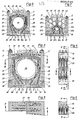
- the mold recesses 27, 27 'formed in the half molds 2, 2' to form a mold space 26 have a shape which is complementary to the outer shape of the tube 23. They are provided with vacuum channels 28, 28 'which run in the vicinity of the wall of the mold recess 27 or 27' and enclose them at a relatively small distance in the case of half molds 2, 2 'which are adjacent to one another. Numerous vacuum slots 29 open from the vacuum channels 28, 28 'into the mold recess 27 or 27'.
- the vacuum channels 28, 28 ' are in a half mold 2, 2' adjacent to each other connected, as shown in Fig. 2.
- the vacuum channels 28 and 28 ' open into the resting on the machine table 1 3o bottom or 3 0' of the half shells 2, 2 '.
- half molds 2, 2 'lying next to one another in pairs they overlap with vacuum connections 31, 31' which are attached to the machine table 1 and which are in turn connected to a vacuum pump, which will be discussed further below.
- cooling channels 33, 33 ' are provided in the half molds 2, 2', the cooling channels 33, 33 'having no connection to one another in the half molds 2, 2' assigned to one another in pairs. They also start on the respective underside 3 0 , 3 o 'of the corresponding half mold 2, 2', where, in the case of adjacent half molds 2, 2 ', they overlap with cooling water inflows 34, 34' formed in the machine table 1. From there, the cooling channels 33, 33 'lead around the respective mold recess 27, 27' at a distance. In the embodiment according to FIGS.
- cooling channels 33, 33 '- viewed in the direction of production 4 - are each arranged at a relatively small distance from one another.
- two cooling channels 33 and 33 ' which are adjacent to one another in the direction of production 4 are connected to one another in such a way that the corresponding additional cooling channels 35 and 35' are connected to one another by a corresponding inclination to one another.
- cooling channel 33 or 33 'to the cooling water inflow 34 or 34' is attached is closed, the cooling channel following in the production direction 4 can be connected in this way to a cooling water return flow 36, 36 'formed in the machine table 1, as can be seen in particular from the left half of FIG. 2.
- the direction of cooling water flow is indicated by the directional arrows 37.
- FIG. 5 shows half molds 2, 2 ', which - as is also apparent from the illustration in comparison to FIG. 2 - are designed for the production of pipes of smaller diameter.
- the vacuum channels 28, 28 'with the vacuum slots 29 are identical to the design according to FIGS. 2 to 6.
- the cooling channels 33a and 33'a are of a similar design to those in the embodiment according to FIGS. 2 to 5, ie they are on the underside 3o or 3 0 'of the corresponding half molds 2, 2' with cooling water inflows 34 and . 34 'connected if they lie in pairs in the molding section. However, they do not have any additional cooling channels, but are each provided at their upper end with an opening 38 or 38 ', by means of which two cooling channels 33a or 33'a, one behind the other in the production direction 4, are connected to one another.
- the cooling water flows according to the arrows 37 and is at the bottom or 3o 3o 'of the respective H albkokille 2 or 2' in a vacuum port 31a or 31'a derived in the accordingly, the respective K ühlkanal 33 'or 33' a flows out.
- vacuum channels 28 and 28' on the one hand and cooling channels 33 'and 33'a have no connection with one another.
- the respective half mold 2, 2 ' is cooled well in the region of the toothing 16.
- the half molds 2, 2 ' are formed with shaped recesses 27, 27' for the production of pipes of particularly small diameters, for example from 10 to 22 mm.
- vacuum channels 28b and 28'b are provided, which are each connected to the corresponding shaped recess 27 or 27 'only via a vacuum slot 29.
- cooling channels 33b, 33'b are provided, the inner at their upper ends JE w Eils again via apertures 38, 38 'are connected together.
- the mold recesses 27, 27 'forming the mold space 26 are arranged relatively deep in the half molds 2, 2'; Cavities 39, which are designed as bores extending in the direction of production 4, are provided above to save material and weight.
- the reason for this configuration is that tubes 23 with different diameters have to be produced on a given device with half molds 2, 2 'with a given height, so that there is sufficient space in the half molds 2, 2' in each case, shaped recesses 27, 27 'of different sizes.
- a temperature sensor 40 is provided according to FIG. 8, which is fitted with a slide shoe 41, for example made of brass, on the flat top 42 of a half mold 2, next to the toothing 16 of which rests, so that the temperature of the continuously running half molds 2 is continuously measured at this point.
- the temperature sensor 4o is carried by a mounting bracket 43, which in turn is attached to the bracket 2o.
- the temperature sensor 4o is connected to a temperature control device 45 by means of an electrical line 44.
- the target temperature can by means of a knob 46, which is made visible to a set point temperature display 47th
- a target / actual value comparison takes place between the actual temperature reported by the temperature sensor 4o and the set target temperature.
- a signal is sent via line 48 to a control valve 49 designed as a solenoid valve, which is arranged in a cooling water inflow line 5o, which is connected via a pipe branch 51 to the cooling water inflows 34 and 34 'in .Machine table 1 is connected.
- a control valve 49 designed as a solenoid valve
- the cooling water return flows 36, 36 'formed in the machine table 1 are connected to a common vacuum line 52, so that the slight excess pressure of the cooling water in the cooling channels does not lead to cooling water from the joint between the half mold 2, 2' and machine table 1 emerges.
- the two vacuum connections 31, 31 ' open into a common vacuum chamber 53, into which a connection 54 from a vacuum pump opens. 6 and 7, the cooling water also runs into the vacuum chamber 53; a separate vacuum line 52 is not required.
Landscapes
- Engineering & Computer Science (AREA)
- Manufacturing & Machinery (AREA)
- Mechanical Engineering (AREA)
- Moulds For Moulding Plastics Or The Like (AREA)
- Cookers (AREA)
- Shaping Of Tube Ends By Bending Or Straightening (AREA)
- Forging (AREA)
- Extrusion Moulding Of Plastics Or The Like (AREA)
- Processing And Handling Of Plastics And Other Materials For Molding In General (AREA)
- Blow-Moulding Or Thermoforming Of Plastics Or The Like (AREA)
- Compression Or Coding Systems Of Tv Signals (AREA)
- Transmission Systems Not Characterized By The Medium Used For Transmission (AREA)
Priority Applications (1)
| Application Number | Priority Date | Filing Date | Title |
|---|---|---|---|
| AT82104280T ATE6605T1 (de) | 1981-05-22 | 1982-05-15 | Vorrichtung zur herstellung von kunststoffrohren mit querrillen. |
Applications Claiming Priority (2)
| Application Number | Priority Date | Filing Date | Title |
|---|---|---|---|
| DE19813120480 DE3120480A1 (de) | 1981-05-22 | 1981-05-22 | Vorrichtung zur herstellung von kunststoffrohren mit querrillen |
| DE3120480 | 1981-05-22 |
Publications (2)
| Publication Number | Publication Date |
|---|---|
| EP0065729A1 true EP0065729A1 (fr) | 1982-12-01 |
| EP0065729B1 EP0065729B1 (fr) | 1984-03-14 |
Family
ID=6133024
Family Applications (1)
| Application Number | Title | Priority Date | Filing Date |
|---|---|---|---|
| EP82104280A Expired EP0065729B1 (fr) | 1981-05-22 | 1982-05-15 | Dispositif pour la production de tubes en matière plastique avec cannelures transverses |
Country Status (9)
| Country | Link |
|---|---|
| US (1) | US4492551A (fr) |
| EP (1) | EP0065729B1 (fr) |
| JP (1) | JPS57195626A (fr) |
| AT (1) | ATE6605T1 (fr) |
| CA (1) | CA1170808A (fr) |
| DE (2) | DE3120480A1 (fr) |
| DK (1) | DK152570C (fr) |
| FI (1) | FI75303C (fr) |
| NO (1) | NO165140C (fr) |
Cited By (11)
| Publication number | Priority date | Publication date | Assignee | Title |
|---|---|---|---|---|
| US4900503A (en) * | 1987-07-30 | 1990-02-13 | Wilhelm Hegler | Method and apparatus for producing a finned tube from synthetic plastics material |
| EP0281217A3 (fr) * | 1987-02-27 | 1990-11-28 | CULLOM MACHINE TOOL & DIE, INC. | Moule ondulé |
| DE4021564A1 (de) * | 1990-07-06 | 1992-01-09 | Wilhelm Hegler | Vorrichtung zur herstellung von kunststoff-rohren |
| DE19702638C1 (de) * | 1997-01-25 | 1998-02-26 | Unicor Rohrsysteme Gmbh | Vorrichtung zum Herstellen von Querrippen-Rohren |
| DE19702645C1 (de) * | 1997-01-25 | 1998-06-10 | Unicor Rohrsysteme Gmbh | Vorrichtung zum Herstellen von Querrippen-Rohren |
| WO1998032585A1 (fr) * | 1997-01-25 | 1998-07-30 | Unicor Gmbh Rahn Plastmaschinen | Dispositif pour produire des tubes a nervures transversales |
| US6457965B1 (en) | 1999-05-18 | 2002-10-01 | Ralph Peter Hegler | Apparatus for the manufacture of corrugated plastic pipes |
| DE102008021237A1 (de) * | 2008-04-28 | 2009-10-29 | Maintools Gmbh & Co.Kg | Formvorrichtung, insbesondere Corrugator, zum Herstellen von profilierten Kunststoffrohren |
| DE102008021234A1 (de) * | 2008-04-28 | 2009-11-05 | Maintools Gmbh & Co.Kg | Formvorrichtung, insbesondere Corrugator, zum Herstellen von profilierten Kunststoffrohren |
| CN102700037A (zh) * | 2012-05-31 | 2012-10-03 | 无锡市侨诺塑机有限公司 | 成型机成型模块用快速冷却机构 |
| CN106553322A (zh) * | 2016-11-08 | 2017-04-05 | 浙江双林机械股份有限公司 | 塑料波纹管成型机滑动座运行轨道 |
Families Citing this family (41)
| Publication number | Priority date | Publication date | Assignee | Title |
|---|---|---|---|---|
| US5059109A (en) * | 1989-12-26 | 1991-10-22 | Cullom Machine Tool & Die, Inc. | Corrugated mold block |
| DE4111229A1 (de) * | 1991-04-08 | 1992-10-15 | Wilhelm Hegler | Vorrichtung zur herstellung von kunststoff-rohren |
| DE4111228A1 (de) * | 1991-04-08 | 1992-10-15 | Wilhelm Hegler | Vorrichtung zur herstellung von kunststoff-rohren |
| DE4210482A1 (de) * | 1992-03-31 | 1993-10-07 | Wilhelm Hegler | Verfahren und Vorrichtung zur fortlaufenden Herstellung eines Verbundrohres mit Rohr-Muffe |
| US5257924A (en) * | 1992-06-19 | 1993-11-02 | Cullom Machine Tool & Die, Inc. | Plastic tile corrugator |
| US5531583A (en) * | 1993-04-15 | 1996-07-02 | Cullom Machine Tool & Die, Inc. | Vacuum mold blocks with cooling for corrugated tubing |
| US5545369A (en) * | 1993-09-08 | 1996-08-13 | Corma, Inc. | Clamshell corrugators and the like |
| DE19504501A1 (de) * | 1995-02-13 | 1996-08-14 | Wilhelm Hegler | Verfahren und Anlage zur Herstellung eines Mehrschicht-Rohres aus thermoplastischem Kunststoff, insbesondere Polyolefin |
| DE19535231A1 (de) * | 1995-09-22 | 1997-03-27 | Hegler Ralph Peter | Vorrichtung zur Herstellung von Rohren aus thermoplastischem Kunststoff mit Querprofilierung |
| US5573787A (en) * | 1995-09-28 | 1996-11-12 | Lupke; Manfred A. A. | Mold apparatus with cooling channels |
| DE19700028C2 (de) * | 1997-01-02 | 2002-08-08 | Unitec Gmbh Tech Entwicklungen | Vorrichtung zum kontinuierlichen Herstellen von flexiblen Kunststoff-Wellrohren in Wellrohrformmaschinen |
| DE19702647C1 (de) * | 1997-01-25 | 1998-02-26 | Unicor Rohrsysteme Gmbh | Vorrichtung zum Herstellen von Querrippen-Rohren |
| WO1998040198A1 (fr) * | 1997-03-12 | 1998-09-17 | Lupke Manfred Arno Alfred | Procede et dispositif de refroidissement de produit dans un moule |
| DE19724857C1 (de) * | 1997-06-12 | 1998-07-16 | Unicor Rohrsysteme Gmbh | Verfahren und Vorrichtung zur Herstellung von Kunststoff-Wellrohren |
| DE10006380A1 (de) | 2000-02-12 | 2001-08-16 | Ralph Peter Hegler | Vorrichtung zur Herstellung von profilierten Kunststoff-Rohren |
| DE20104922U1 (de) * | 2001-03-21 | 2002-07-25 | Drossbach GmbH & Co KG, 86641 Rain | Wellrohranlage |
| DE10148294C1 (de) * | 2001-09-29 | 2003-01-16 | Unicor Rohrsysteme Gmbh | Formbackenhälfte für einen Corrugator zum Herstellen von Querrippenrohren |
| DE10152638A1 (de) * | 2001-10-16 | 2003-04-24 | Ralph Peter Hegler | Vorrichtung zur Herstellung von gewellten Kunststoff-Rohren |
| CA2403223A1 (fr) * | 2002-09-11 | 2004-03-11 | Manfred A. A. Lupke | Dispositif de moulage a refroidissement externe du bloc de moulage |
| CA2411881C (fr) * | 2002-11-15 | 2009-09-15 | Manfred A. A. Lupke | Appareil de moulage comportant des blocs a faces reglables |
| DE10257363C1 (de) * | 2002-12-09 | 2003-10-23 | Unicor Rohrsysteme Gmbh | Formbackenhälfte für eine Vorrichtung zur Erstellung von Querrippenrohren |
| CA2444096C (fr) * | 2003-10-01 | 2007-05-08 | Manfred A. A. Lupke | Moule mobile refroidi de l'exterieur |
| US8733405B2 (en) | 2005-03-14 | 2014-05-27 | Advanced Drainage Systems, Inc. | Corrugated pipe with outer layer |
| US7484535B2 (en) * | 2005-03-14 | 2009-02-03 | Advanced Drainage Systems, Inc. | Corrugated pipe with outer layer |
| DE102006048512B4 (de) * | 2006-10-13 | 2014-03-06 | Ralph Peter Hegler | Vorrichtung zur Herstellung von Verbund-Rohren |
| CA2622695C (fr) * | 2007-02-26 | 2015-11-03 | Advanced Drainage Systems, Inc. | Appareil et methode de voie d'acheminement de filiere d'extrusion pour tubes |
| CA2622692C (fr) * | 2007-02-26 | 2015-10-06 | Advanced Drainage Systems, Inc. | Matrice de tuyau double paroi a rapport defini |
| WO2008153691A1 (fr) * | 2007-05-23 | 2008-12-18 | Advanced Drainage Systems, Inc. | Système et procédé de commande d'accélération d'une extrudeuse |
| US8820800B2 (en) * | 2007-11-16 | 2014-09-02 | Advanced Drainage Systems, Inc. | Multi-wall corrugated pipe couplings and methods |
| US8820801B2 (en) * | 2007-11-16 | 2014-09-02 | Advanced Drainage System, Inc. | Multi-wall corrugated pipe couplings and methods |
| US8114324B2 (en) | 2008-10-14 | 2012-02-14 | Advanced Drainage Systems, Inc. | Apparatus and method for pressing an outer wall of pipe |
| US7988438B2 (en) * | 2008-02-11 | 2011-08-02 | Advanced Drainage Systems, Inc. | Extrusion die vacuum seals |
| US8550807B2 (en) * | 2008-05-28 | 2013-10-08 | Advanced Drainage Systems, Inc. | In-mold punch apparatus and methods |
| US8808610B2 (en) * | 2009-04-01 | 2014-08-19 | Patrick E. Scharf | Systems and methods for cooling moving molds |
| DE102009035040B4 (de) | 2009-07-28 | 2011-12-15 | Ralph Peter Hegler | Verfahren zur fortlaufenden Herstellung eines Rohres und Vorrichtung zur Durchführung des Verfahrens |
| CN102189661A (zh) * | 2010-03-04 | 2011-09-21 | 上海金纬管道设备制造有限公司 | 塑料波纹管成型装置 |
| DE102016224761A1 (de) * | 2015-12-11 | 2017-06-14 | Sms Group Gmbh | Lagerbock zur Aufnahme eines Lagers für eine Rolle |
| DE102019127168B3 (de) | 2019-10-09 | 2021-02-18 | Unicor Gmbh | Vorrichtung zur Herstellung von Kunststoffrohr, Formbacke, Formbackenpaar und Verfahren zur Herstellung von Kunststoffrohr |
| DE102019127836A1 (de) | 2019-10-15 | 2021-04-15 | Unicor Gmbh | Vorrichtung zur Herstellung von Kunststoffrohren unter Einsatz eines Kühldorns mit Sensoreinrichtung |
| CN112277294A (zh) * | 2020-11-06 | 2021-01-29 | 石图里包装材料(扬州)有限公司 | 一种具有快速降温功能的全自动高压压空成型机 |
| WO2022204408A1 (fr) * | 2021-03-23 | 2022-09-29 | Koska Family Limited | Systèmes et procédés de vide par étapes de machine de soufflage-remplissage-scellage (bfs) rotative |
Citations (3)
| Publication number | Priority date | Publication date | Assignee | Title |
|---|---|---|---|---|
| DE2061027A1 (de) * | 1970-12-11 | 1972-06-22 | Wilhelm Hegler | Vorrichtung zur Herstellung von Kunststoffrohren mit Querprofilierung |
| DE2537184A1 (de) * | 1975-08-21 | 1977-03-10 | Oltmanns Ziegelwerk | Anlage zur herstellung von rohr- oder schlauchfoermigen gegenstaenden aus kunststoff |
| DE2732635A1 (de) * | 1977-07-19 | 1979-02-01 | Kirchner Fraenk Rohr | Vorrichtung zum kontinuierlichen herstellen von mit querprofilierungen versehenen kunststoffrohren |
Family Cites Families (9)
| Publication number | Priority date | Publication date | Assignee | Title |
|---|---|---|---|---|
| BE656716A (fr) * | 1964-12-07 | 1965-06-08 | ||
| DE2065048C3 (de) * | 1970-12-11 | 1974-08-15 | Wilhelm 8731 Oerlenbach Hegler | Vorrichtung zum Herstellen von Kunststoffrohren mit Querprofilierung. Ausscheidung aus: 2061027 |
| US3942929A (en) * | 1972-03-08 | 1976-03-09 | Bison-Werke Bahre & Greten Gmbh & Co. Kg | Continuously operating press |
| US3919367A (en) * | 1972-07-13 | 1975-11-11 | Ernest J Maroschak | Method for molding plastic pipe with enlarged portions formed therein |
| US3950118A (en) * | 1974-05-17 | 1976-04-13 | Phillips Petroleum Company | Control of temperature profile across a heat exchanger |
| US4107422A (en) * | 1977-02-02 | 1978-08-15 | Phillips Petroleum Company | Solvent removal from polymer solutions |
| DE2832350A1 (de) * | 1978-07-22 | 1980-01-31 | Wilhelm Hegler | Vorrichtung zur herstellung von rohren aus thermoplastischem kunststoff mit querprofilierung |
| JPS5523738A (en) * | 1978-08-02 | 1980-02-20 | Toko Inc | Switching regulator |
| JPS5831290B2 (ja) * | 1979-01-19 | 1983-07-05 | 鳥居化成有限会社 | 螺旋波付プラスチック管の製造装置 |
-
1981
- 1981-05-22 DE DE19813120480 patent/DE3120480A1/de not_active Withdrawn
-
1982
- 1982-04-27 CA CA000401720A patent/CA1170808A/fr not_active Expired
- 1982-05-10 US US06/376,737 patent/US4492551A/en not_active Expired - Lifetime
- 1982-05-15 DE DE8282104280T patent/DE3260066D1/de not_active Expired
- 1982-05-15 EP EP82104280A patent/EP0065729B1/fr not_active Expired
- 1982-05-15 AT AT82104280T patent/ATE6605T1/de not_active IP Right Cessation
- 1982-05-17 FI FI821731A patent/FI75303C/fi not_active IP Right Cessation
- 1982-05-19 JP JP57083358A patent/JPS57195626A/ja active Granted
- 1982-05-19 NO NO821663A patent/NO165140C/no unknown
- 1982-05-21 DK DK230182A patent/DK152570C/da not_active IP Right Cessation
Patent Citations (3)
| Publication number | Priority date | Publication date | Assignee | Title |
|---|---|---|---|---|
| DE2061027A1 (de) * | 1970-12-11 | 1972-06-22 | Wilhelm Hegler | Vorrichtung zur Herstellung von Kunststoffrohren mit Querprofilierung |
| DE2537184A1 (de) * | 1975-08-21 | 1977-03-10 | Oltmanns Ziegelwerk | Anlage zur herstellung von rohr- oder schlauchfoermigen gegenstaenden aus kunststoff |
| DE2732635A1 (de) * | 1977-07-19 | 1979-02-01 | Kirchner Fraenk Rohr | Vorrichtung zum kontinuierlichen herstellen von mit querprofilierungen versehenen kunststoffrohren |
Cited By (21)
| Publication number | Priority date | Publication date | Assignee | Title |
|---|---|---|---|---|
| EP0281217A3 (fr) * | 1987-02-27 | 1990-11-28 | CULLOM MACHINE TOOL & DIE, INC. | Moule ondulé |
| US4900503A (en) * | 1987-07-30 | 1990-02-13 | Wilhelm Hegler | Method and apparatus for producing a finned tube from synthetic plastics material |
| EP0301189A3 (en) * | 1987-07-30 | 1990-09-05 | Wilhelm Hegler | Method and apparatus for manufacturing a ribbed plastic pipe |
| DE4021564A1 (de) * | 1990-07-06 | 1992-01-09 | Wilhelm Hegler | Vorrichtung zur herstellung von kunststoff-rohren |
| US6149421A (en) * | 1997-01-25 | 2000-11-21 | Unicor Gmbh Rahn Plastmaschinen | Device for producing cross-finned pipes |
| CN1064888C (zh) * | 1997-01-25 | 2001-04-25 | 乌尼科拉恩塑料机械有限公司 | 用于制造横肋片管的装置 |
| WO1998032585A1 (fr) * | 1997-01-25 | 1998-07-30 | Unicor Gmbh Rahn Plastmaschinen | Dispositif pour produire des tubes a nervures transversales |
| WO1998032582A1 (fr) * | 1997-01-25 | 1998-07-30 | Unicor Gmbh Rahn Plastmaschinen | Dispositif pour produire des tubes a nervures transversales |
| WO1998032584A1 (fr) * | 1997-01-25 | 1998-07-30 | Unicor Gmbh Rahn Plastmaschinen | Dispositif pour produire des tubes a nervures transversales |
| DE19702637C1 (de) * | 1997-01-25 | 1998-08-13 | Unicor Rohrsysteme Gmbh | Vorrichtung zum Herstellen von Querrippen-Rohren |
| DE19702638C1 (de) * | 1997-01-25 | 1998-02-26 | Unicor Rohrsysteme Gmbh | Vorrichtung zum Herstellen von Querrippen-Rohren |
| US6206670B1 (en) | 1997-01-25 | 2001-03-27 | Unicor Gmbh Rahn Plastmaschinen | Process for the production if transversely ribbed tubes |
| CN1064889C (zh) * | 1997-01-25 | 2001-04-25 | 乌尼科拉恩塑料机械有限公司 | 用于制造横肋片管的装置 |
| DE19702645C1 (de) * | 1997-01-25 | 1998-06-10 | Unicor Rohrsysteme Gmbh | Vorrichtung zum Herstellen von Querrippen-Rohren |
| CN1064886C (zh) * | 1997-01-25 | 2001-04-25 | 乌尼科拉恩塑料机械有限公司 | 用于制造横肋片管的装置 |
| US6457965B1 (en) | 1999-05-18 | 2002-10-01 | Ralph Peter Hegler | Apparatus for the manufacture of corrugated plastic pipes |
| DE102008021237A1 (de) * | 2008-04-28 | 2009-10-29 | Maintools Gmbh & Co.Kg | Formvorrichtung, insbesondere Corrugator, zum Herstellen von profilierten Kunststoffrohren |
| DE102008021234A1 (de) * | 2008-04-28 | 2009-11-05 | Maintools Gmbh & Co.Kg | Formvorrichtung, insbesondere Corrugator, zum Herstellen von profilierten Kunststoffrohren |
| CN102700037A (zh) * | 2012-05-31 | 2012-10-03 | 无锡市侨诺塑机有限公司 | 成型机成型模块用快速冷却机构 |
| CN106553322A (zh) * | 2016-11-08 | 2017-04-05 | 浙江双林机械股份有限公司 | 塑料波纹管成型机滑动座运行轨道 |
| CN106553322B (zh) * | 2016-11-08 | 2018-12-14 | 浙江双林机械股份有限公司 | 塑料波纹管成型机滑动座运行轨道 |
Also Published As
| Publication number | Publication date |
|---|---|
| NO165140C (no) | 1991-01-09 |
| NO165140B (no) | 1990-09-24 |
| EP0065729B1 (fr) | 1984-03-14 |
| JPH0253221B2 (fr) | 1990-11-16 |
| DK152570B (da) | 1988-03-21 |
| FI75303C (fi) | 1988-06-09 |
| FI821731A0 (fi) | 1982-05-17 |
| DK152570C (da) | 1988-09-19 |
| CA1170808A (fr) | 1984-07-17 |
| US4492551A (en) | 1985-01-08 |
| FI75303B (fi) | 1988-02-29 |
| DE3260066D1 (en) | 1984-04-19 |
| JPS57195626A (en) | 1982-12-01 |
| NO821663L (no) | 1982-11-23 |
| ATE6605T1 (de) | 1984-03-15 |
| DK230182A (da) | 1982-11-23 |
| DE3120480A1 (de) | 1982-12-09 |
Similar Documents
| Publication | Publication Date | Title |
|---|---|---|
| EP0065729B1 (fr) | Dispositif pour la production de tubes en matière plastique avec cannelures transverses | |
| EP0301189B1 (fr) | Procédé et dispositif de fabrication d'un tube nervuré en matière plastique | |
| DE69420995T2 (de) | Wellvorrichtung für Kunststoffrohre und Formblöcke | |
| DE2947729C2 (fr) | ||
| EP0033158A1 (fr) | Dispositif pour le traitement en continu de caoutchouc, d'élastomères ou de matières plastiques vulcanisables ou réticulables | |
| DE2545133C3 (de) | Vorrichtung zum Blasformen von Behältern aus Vorf ormlingen | |
| EP1254014B1 (fr) | Dispositif de fabrication de tubes en plastique profiles | |
| CH632429A5 (de) | Kollabierender kern fuer giessformen, insbesondere spritzgiessformen. | |
| EP0542935B1 (fr) | Dispositif pour le refroidissement des moules de sortie d'une machine a mouler le verre | |
| DE10224461B4 (de) | Formgebungseinrichtung für eine Extrusionsanlage | |
| EP0464411B1 (fr) | Dispositif pour la production de tuyaux en matière plastique | |
| DE69707314T2 (de) | Extruder | |
| DE3243184C2 (de) | Düsenwechseleinrichtung für Kunststoffextruder | |
| DE10152638A1 (de) | Vorrichtung zur Herstellung von gewellten Kunststoff-Rohren | |
| DE19815276B4 (de) | Nachbehandlungsverfahren für einen extrudierten Gegenstand | |
| DE102009027437A1 (de) | Vorrichtung und Verfahren zum Kühlen von Kunststoffprofilen | |
| DE2639484A1 (de) | Verfahren und vorrichtung zur herstellung von formteilen aus kunststoffgranulat | |
| DE2924269C3 (de) | Vorrichtung zur Steuerung des Strömungsquerschnittes in einem Schneckenextruder | |
| EP1206341A1 (fr) | Cylindre pour une extrudeuse a double vis | |
| DE2500185C2 (de) | Blasformmaschine | |
| DE2009914B2 (de) | Folienblaskopf zur herstellung von kunststoff-schlauchfolien | |
| DE2354134A1 (de) | Verteiler zum spritzgiessen thermoempfindlicher kunststoffe in mehrfachformwerkzeuge | |
| EP0595198B1 (fr) | Appareil et méthode pour la fabrication de profilés allongés en matières plastiques | |
| DE3043306A1 (de) | Doppelschneckenextruder mit verschleissfestem bimetall-einsatz | |
| DE1704769C3 (de) | Strangpresskopf zum kontinuierlichen Ausspritzen einer Kunststoffolie,die mit zwei in Spritzrichtung verlaufenden Verschlussleisten versehen ist |
Legal Events
| Date | Code | Title | Description |
|---|---|---|---|
| PUAI | Public reference made under article 153(3) epc to a published international application that has entered the european phase |
Free format text: ORIGINAL CODE: 0009012 |
|
| 17P | Request for examination filed |
Effective date: 19820916 |
|
| AK | Designated contracting states |
Designated state(s): AT DE FR GB NL SE |
|
| GRAA | (expected) grant |
Free format text: ORIGINAL CODE: 0009210 |
|
| AK | Designated contracting states |
Designated state(s): AT DE FR GB NL SE |
|
| REF | Corresponds to: |
Ref document number: 6605 Country of ref document: AT Date of ref document: 19840315 Kind code of ref document: T |
|
| REF | Corresponds to: |
Ref document number: 3260066 Country of ref document: DE Date of ref document: 19840419 |
|
| ET | Fr: translation filed | ||
| PLBE | No opposition filed within time limit |
Free format text: ORIGINAL CODE: 0009261 |
|
| STAA | Information on the status of an ep patent application or granted ep patent |
Free format text: STATUS: NO OPPOSITION FILED WITHIN TIME LIMIT |
|
| 26N | No opposition filed | ||
| REG | Reference to a national code |
Ref country code: FR Ref legal event code: CL |
|
| EAL | Se: european patent in force in sweden |
Ref document number: 82104280.1 |
|
| PGFP | Annual fee paid to national office [announced via postgrant information from national office to epo] |
Ref country code: AT Payment date: 19950410 Year of fee payment: 14 |
|
| PG25 | Lapsed in a contracting state [announced via postgrant information from national office to epo] |
Ref country code: AT Effective date: 19960515 |
|
| PGFP | Annual fee paid to national office [announced via postgrant information from national office to epo] |
Ref country code: NL Payment date: 19960529 Year of fee payment: 15 |
|
| PGFP | Annual fee paid to national office [announced via postgrant information from national office to epo] |
Ref country code: FR Payment date: 19970417 Year of fee payment: 16 |
|
| PGFP | Annual fee paid to national office [announced via postgrant information from national office to epo] |
Ref country code: SE Payment date: 19970522 Year of fee payment: 16 |
|
| PGFP | Annual fee paid to national office [announced via postgrant information from national office to epo] |
Ref country code: DE Payment date: 19970724 Year of fee payment: 16 |
|
| PG25 | Lapsed in a contracting state [announced via postgrant information from national office to epo] |
Ref country code: NL Effective date: 19971201 |
|
| NLV4 | Nl: lapsed or anulled due to non-payment of the annual fee |
Effective date: 19971201 |
|
| PGFP | Annual fee paid to national office [announced via postgrant information from national office to epo] |
Ref country code: GB Payment date: 19980429 Year of fee payment: 17 |
|
| PG25 | Lapsed in a contracting state [announced via postgrant information from national office to epo] |
Ref country code: SE Free format text: LAPSE BECAUSE OF NON-PAYMENT OF DUE FEES Effective date: 19980516 |
|
| PG25 | Lapsed in a contracting state [announced via postgrant information from national office to epo] |
Ref country code: FR Free format text: LAPSE BECAUSE OF NON-PAYMENT OF DUE FEES Effective date: 19980531 |
|
| EUG | Se: european patent has lapsed |
Ref document number: 82104280.1 |
|
| PG25 | Lapsed in a contracting state [announced via postgrant information from national office to epo] |
Ref country code: DE Free format text: LAPSE BECAUSE OF NON-PAYMENT OF DUE FEES Effective date: 19990302 |
|
| REG | Reference to a national code |
Ref country code: FR Ref legal event code: ST |
|
| PG25 | Lapsed in a contracting state [announced via postgrant information from national office to epo] |
Ref country code: GB Free format text: LAPSE BECAUSE OF NON-PAYMENT OF DUE FEES Effective date: 19990515 |
|
| GBPC | Gb: european patent ceased through non-payment of renewal fee |
Effective date: 19990515 |