EP0065737A1 - Magnetische Spreizvorrichtung für einen Blechstapel aus magnetisierbaren Einzelblechen mit Mittenbohrung - Google Patents
Magnetische Spreizvorrichtung für einen Blechstapel aus magnetisierbaren Einzelblechen mit Mittenbohrung Download PDFInfo
- Publication number
- EP0065737A1 EP0065737A1 EP82104322A EP82104322A EP0065737A1 EP 0065737 A1 EP0065737 A1 EP 0065737A1 EP 82104322 A EP82104322 A EP 82104322A EP 82104322 A EP82104322 A EP 82104322A EP 0065737 A1 EP0065737 A1 EP 0065737A1
- Authority
- EP
- European Patent Office
- Prior art keywords
- spreading
- magnetic
- stack
- switchable
- mandrel
- Prior art date
- Legal status (The legal status is an assumption and is not a legal conclusion. Google has not performed a legal analysis and makes no representation as to the accuracy of the status listed.)
- Granted
Links
Images
Classifications
-
- B—PERFORMING OPERATIONS; TRANSPORTING
- B21—MECHANICAL METAL-WORKING WITHOUT ESSENTIALLY REMOVING MATERIAL; PUNCHING METAL
- B21D—WORKING OR PROCESSING OF SHEET METAL OR METAL TUBES, RODS OR PROFILES WITHOUT ESSENTIALLY REMOVING MATERIAL; PUNCHING METAL
- B21D43/00—Feeding, positioning or storing devices combined with, or arranged in, or specially adapted for use in connection with, apparatus for working or processing sheet metal, metal tubes or metal profiles; Associations therewith of cutting devices
- B21D43/20—Storage arrangements; Piling or unpiling
- B21D43/24—Devices for removing sheets from a stack
-
- B—PERFORMING OPERATIONS; TRANSPORTING
- B65—CONVEYING; PACKING; STORING; HANDLING THIN OR FILAMENTARY MATERIAL
- B65G—TRANSPORT OR STORAGE DEVICES, e.g. CONVEYORS FOR LOADING OR TIPPING, SHOP CONVEYOR SYSTEMS OR PNEUMATIC TUBE CONVEYORS
- B65G59/00—De-stacking of articles
- B65G59/02—De-stacking from the top of the stack
- B65G59/04—De-stacking from the top of the stack by suction or magnetic devices
- B65G59/045—De-stacking from the top of the stack by suction or magnetic devices with a stepwise upward movement of the stack
Definitions
- the invention relates to a magnetic expansion device according to the preamble of patent claim 1.
- a standing centering mandrel for guiding the spread individual sheets is necessary for each sheet stack, which defines the maximum height of the sheet stack and whose outer diameter must be adapted to the center hole of the individual sheets.
- the upright magnetic spreading device must be adapted to the outside diameter of the stack of sheets so that it surrounds the sheet stack at a certain uniform distance. Since this spreading device surrounds the sheet stack in the upper area, access to the topmost individual that is spread out is possible sheet metal difficult and because of the arrangement, an increased space requirement in the vicinity of each sheet stack is required for the installation of the spreading device.
- the invention has for its object to provide a magnetic spreading device in which the centering mandrels for the individual sheet stacks are unnecessary and the space required around each sheet stack can be kept smaller and the height of the sheet stack can be freely selected according to the respective needs, where appropriate the spreading device as Means of transport can be used at least for partial stacks.
- a stack of sheet metal made of magnetizable single sheets with a central bore is freely supported, the central bores of the individual sheets being aligned precisely enough to counter the sinking of a suspended and lifted in the direction of arrow A. and lowerable centering mandrel 1 or 1 'from above into the sheet stack.
- a short centering mandrel 1 with only one electro-spreading magnet 8 inside can be unmagnetized.
- pipe body are used.
- the tubular body is closed at the bottom with a non-magnetic base plate 2 and contains only the cast-in electro-spreading magnet 8.
- the upper side of the tubular body is closed by a non-magnetic end plate 3 protruding beyond the mandrel circumference, which is on the upper side via a carrying device 4 with a lifting device or slide unit, not shown connected is.
- the carrying device 4 receives the connection connections to the electro-spreading magnet.
- switchable adhesive devices 5, 6 On the underside of the end plate 3 there are two diametrically arranged switchable adhesive devices 5, 6 for the spread-out uppermost single sheet and a contactless electrical scanner 7 which ends in the axial direction of the mandrel in front of the undersides of the adhesive devices.
- the adhesive devices 5, 6 can be actuated independently of the electro-spreading magnet 8.
- vacuum suction devices with a switchable vent can be provided as adhesive devices, otherwise switchable electromagnets can be used for this purpose.
- the single sheet can be removed by hand or with a transport device after switching off the holding devices 5, 6 .
- the electro-spreading magnet 8 and the holding devices 5, 6 on again, the upper area of the sheet stack is spread again and the single sheet now lying on top is lifted off.
- control device 7 can be controlled by the contactless scanner 7 Lifting device 16 are given, which in turn raises the stack remainder over the pallet 15 to the initial distance. It is assumed that the base plate 2 is at a sufficient distance from the upper edge of the remainder of the stack after the spread-out partial stack has fallen off, in order to be able to remove the uppermost single sheet between the two.
- the centering mandrel with the individual sheet held must be raised in the direction of arrow A in response to a control signal and / or the pallet 15 must be lowered in the direction of arrow C.
- the spreading device can also be used, the spreading device with the electro-spreading magnet 8 switched on by a locally changeable, not shown hoist is adjusted in the direction of arrows A and B.
- both the electro-spreading magnet 8 and the electro-spreading magnet 9 are switched on, so that the associated partial stacks 12 and 13 are lifted from the rest of the stack 14 and spread apart.
- the stack remainder 14 is divided into two further partial stacks and these are spread out, so that a total of four spread partial stacks are transported through the centering mandrel 1 'and the individual partial stacks can be stored at one or different locations by switching off the individual electro-spreading magnets 8 to 11.
Landscapes
- Engineering & Computer Science (AREA)
- Mechanical Engineering (AREA)
- Sheets, Magazines, And Separation Thereof (AREA)
- Pile Receivers (AREA)
- De-Stacking Of Articles (AREA)
Abstract
Description
- Die Erfindung betrifft eine magnetische Spreizvorrichtung nach dem Oberbegriff des Patentanspruches 1.
- Bei den bekannten magnetischen Spreizvorrichtungen für solche Blechstapel, die auf Paletten mit stehend angeordneten Zentrierdornen gelagert sind, werden zum Aufspreizen der an den Zentrierdornen geführten oberen Endbereiche der Blechstapel zwecks Einzelentnahme der jeweils obersten Einzelbleche um den äußeren Umfang der besagten Endbereiche stehend gelagerte Permanentspreizmagnete angebracht, die in ihrem axial erstreckten Wirkungsbereich die Einzelbleche fächerförmig aufspreizen, so daß das jeweils oberste Einzelblech zur Zuführung an anderorts befindliche Weiterverarbeitungsstellen abgenommen und dorthin gebracht werden kann. Dies ist z.B. bei gelagerten Blechronden für elektrische Maschinen oder Apparate zur Zuführung der Einzelbleche an Stanzmaschinen notwendig.
- Bei dieser Art ist für jeden Blechstapel ein stehender Zentrierdorn zur Führung der aufgespreizten Einzelbleche notwendig, der die maximale Höhe des Blechstapels festlegt und dessen Außendurchmesser an die Mittenbohrung der Einzelbleche angepaßt sein muß. Weiterhin muß die stehend angeordnete magnetische Spreizvorrichtung an den Außendurchmesser der Blechstapel angepaßt sein, so daß sie den Blechstapel in einem bestimmten gleichmäßigen Abstand umgibt. Da diese Spreizvorrichtung den Blechstapel im oberen Bereich umgibt, ist der Zugriff zum jeweils aufgespreizten obersten Einzelblech erschwert und wegen der besagten Anordnung ein erhöhter Platzbedarf in der Umgebung jedes Blechstapels für die Aufstellung der Spreizvorrichtung erforderlich.
- Der Erfindung liegt die Aufgabe zugrunde, eine magnetische Spreizvorrichtung zu schaffen, bei der die Zentrierdorne für die einzelnen Blechstapel entbehrlich sind und der Platzbedarf um jeden Blechstapel herum kleiner gehalten sowie die Höhe der Blechstapel den jeweiligen Bedürfnissen entsprechend freigewählt werden können, wobei gegebenenfalls die Spreizvorrichtung als Transportmittel wenigstens für Teilstapel mitverwendet werden kann.
- Die Lösung der gestellten Aufgabe gelingt durch die Maßnahmen nach dem Kennzeichen des Patentanspruches 1.
- Vorteilhafte Ausgestaltung der Erfindung sind Gegenstand von Unteransprüchen.
- Ein Ausführungsbeispiel der Erfindung ist schematisch in der Zeichnung dargestellt und nachfolgend näher erläutert.
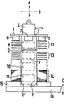
- Auf einer Palette 15, die mittels einer nur angedeuteten Hubeinrichtung 16 in Pfeilrichtung C höhenverstellbar ist, ist ein Blechstapel aus magnetisierbaren Einzelblechen mit Mittenbohrung frei gelagert, wobei die Mittenbohrungen der Einzelbleche ausreichend genau fluchten, um das Einsenken eines hängend angeordneten und in Pfeilrichtung A heb- und senkbaren Zentrierdornes 1 bzw. 1' von oben her in den Blechstapel zu ermöglichen.
- Wenn es in der Hauptsache darum geht, von einem Blechstapel jeweils das oberste Einzelblech für sich abzunehmen, dann kann ein kurzer Zentrierdorn 1 mit nur einem Elektrospreizmagneten 8 im Innern seires unmagneti-schen Rohrkörpers Verwendung finden. Der Rohrkörper ist mit einer unmagnetischen Bodenplatte 2 nach unten abgeschlossen und enthält nur den eingegossenen Elektrospreizmagneten 8. Der Rohrkörper ist an seiner Oberseite von einer unmagnetischen, über den Dornumfang vorragenden Abschlußplatte 3 abgeschlossen, die oberseitig über eine Tragvorrichtung 4 mit einem nicht dargestellten Hebezeug oder Schlitteneinheit verbunden ist. Die Tragvorrichtung 4 nimmt die Anschlußverbindungen zu dem Elektrospreizmagneten auf.
- An der Unterseite der Abschlußplatte 3 sind zwei diametral angeordnete schaltbare Haftvorrichtungen 5, 6 für das aufgespreizte oberste Einzelblech sowie ein berührungsloser elektrischer Abtaster 7 vorgesehen, der in axialer Dornrichtung vor den Unterseiten der Haftvorrichtungen endet. Die Haftvorrichtungen 5, 6 können unabhängig von dem Elektrospreizmagneten 8 betätigt werden. Für den Fall, daß ungelochte Einzelbleche abgenommen werden sollen, können Vakuumsauger mit schaltbarer Entlüftung als Haftvorrichtungen vorgesehen sein, ansonsten können hierfür schaltbare Elektromagneten dienen. Sobald das oberste Einzelblech von__den Haftvorrichtungen 5, 6 gehalten ist, kann nach Abschalten des Elektrospreizmagneten 8 und dadurch bedingten Abfall des Teilstapels 12 auf den Stapelrest 14 unter dem Zentrierdorn 1 von Hand oder mit einer Transportvorrichtung das Einzelblech nach Abschalten der Haftvorrichtungen 5, 6 entfernt werden. Durch Wiedereinschalten der Elektrospreizmagneten 8 und der Haftvorrichtungen 5, 6 wird der obere Bereich des Blechstapels wiederum aufgespreizt und das jetzt oben liegende Einzelblech abgehoben.
- Damit der Abstand des Stapelrestes zum Elektrospreizmagneten und den Haftvorrichtungen nicht zu groß wird, um die notwendge Funktion in Frage zu stellen, kann durch den berührungslosen Abtaster 7 ein Steuersignal für die Hubeinrichtung 16 gegeben werden, der den Stapelrest über die Palette 15 wiederum auf die Anfangsentfernung anhebt. Dabei ist unterstellt, daß die Bodenplatte 2 ausreichenden Abstand von der Oberkante des Stapelrestes nach Abfall des aufgespreizten Teilstapels hat, um das oberste Einzelblech zwischen beiden entfernen zu können.
- Andererseits muß der Zentrierdorn mit dem gehaltenen Einzelblech in Abhängigkeit von einem Steuersignal in Pfeilrichtung A gehoben und/oder die Palette 15 in Pfeilrichtung C gesenkt werden.
- Wenn nicht die Abnahme des obersten Einzelbleches, sondern die Verteilung des Blechstapels in Teilstapel an verschiedenen Orten gefordert ist und von diesen jeweils die Einzelbleche zur Weiterverarbeitung abgenommen werden sollen, kann ebenfalls die Spreizvorrichtung verwendet werden, wobei die Spreizvorrichtung mit eingeschalteten Elektrospreizmagneten 8 durch ein ortsver- änderliches, nicht dargestelltes Hebezeug in Pfeilrichtung A und B verstellt wird.
- Zum Transport eines ganzen Blechstapels oder zumindest eines größeren Teiles davon, kann, wie strichpunktiert angedeutet ist, der Zentrierdorn 11 zur Aufnahme mehrerer, untereinander beabstandet angeordneter und gesondert schaltbarer Elektrospreizmagneten 8 bis 11 verlängert und mit einer Bodenplatte 2' abgeschlossen sein.
- Im dargestellten Fall ist bei voll in den Blechstapel eingesenkten Zentrierdorn 1' sowohl der Elektrospreizmagnet 8 als auch der Elektrospreizmagnet 9 eingeschaltet, so daß die zugeordneten Teilstapel 12 und 13 vom Stapelrest 14 abgehoben und aufgespreizt sind. Bei Erregung auch der übrigen Elektrospreizmagneten 10 und 11 ist der Stapelrest 14 in zwei weitere Teilstapel aufgeteilt und diese sind aufgespreizt, so daß insgesamt vier gespreizte Teilstapel durch den Zentrierdorn 1' transportiert und die einzelnen Teilstapel durch Abschalten der einzelnen Elektrospreizmagneten 8 bis 11 an einem oder verschiedenen Orten abgelegt werden können.
Claims (7)
Applications Claiming Priority (2)
| Application Number | Priority Date | Filing Date | Title |
|---|---|---|---|
| DE3121203 | 1981-05-27 | ||
| DE3121203A DE3121203C2 (de) | 1981-05-27 | 1981-05-27 | Magnetische Spreizvorrichtung für einen Blechstapel aus magnetisierbaren Einzelblechen mit Mittenbohrung |
Publications (2)
| Publication Number | Publication Date |
|---|---|
| EP0065737A1 true EP0065737A1 (de) | 1982-12-01 |
| EP0065737B1 EP0065737B1 (de) | 1984-10-24 |
Family
ID=6133399
Family Applications (1)
| Application Number | Title | Priority Date | Filing Date |
|---|---|---|---|
| EP82104322A Expired EP0065737B1 (de) | 1981-05-27 | 1982-05-17 | Magnetische Spreizvorrichtung für einen Blechstapel aus magnetisierbaren Einzelblechen mit Mittenbohrung |
Country Status (4)
| Country | Link |
|---|---|
| US (1) | US4465415A (de) |
| EP (1) | EP0065737B1 (de) |
| JP (1) | JPS57199729A (de) |
| DE (1) | DE3121203C2 (de) |
Cited By (3)
| Publication number | Priority date | Publication date | Assignee | Title |
|---|---|---|---|---|
| EP0399125A1 (de) * | 1989-05-23 | 1990-11-28 | Nippon Sanso Kabushiki Kaisha | Apparat zur Handhabung von gestapelten Werkstücken in Form Blechplatten |
| US5018939A (en) * | 1987-11-13 | 1991-05-28 | Toyota Jidosha Kabushiki Kaisha | Apparatus for separating iron sheets |
| CN107708886A (zh) * | 2015-04-08 | 2018-02-16 | 迈格斯维奇磁性开关技术欧洲有限公司 | 铁磁板散开和抓持装置 |
Families Citing this family (12)
| Publication number | Priority date | Publication date | Assignee | Title |
|---|---|---|---|---|
| JPS6097147A (ja) * | 1983-10-31 | 1985-05-30 | Toyoda Mach Works Ltd | 積層された磁性部品の分離装置 |
| US6638002B1 (en) | 2000-08-17 | 2003-10-28 | Claire T. Martin | Pallet pin sheet fanner |
| US6405857B1 (en) * | 2000-10-18 | 2002-06-18 | Ritek Corporation | Transportation mechanism of magnetic handling for accessing compact disks |
| US6509588B1 (en) | 2000-11-03 | 2003-01-21 | Cardiac Pacemakers, Inc. | Method for interconnecting anodes and cathodes in a flat capacitor |
| DE20115017U1 (de) * | 2001-09-11 | 2003-02-06 | Wagner Magnete GmbH & Co. KG, 87751 Heimertingen | Elektrospreizmagnet |
| US7951479B2 (en) | 2005-05-11 | 2011-05-31 | Cardiac Pacemakers, Inc. | Method and apparatus for porous insulative film for insulating energy source layers |
| US7479349B2 (en) | 2002-12-31 | 2009-01-20 | Cardiac Pacemakers, Inc. | Batteries including a flat plate design |
| US7611549B2 (en) * | 2003-12-22 | 2009-11-03 | Cardiac Pacemakers, Inc. | Magnetic stacking fixture for stacking electrodes |
| DE102005052391B4 (de) * | 2005-10-31 | 2016-12-01 | Evertz Magnetbau Gmbh & Co. Kg | Lasthebemagnet |
| SE530466C2 (sv) * | 2006-09-27 | 2008-06-17 | Brodde Bengtsson | Förfarande och anordning för separering av i en stapel placerade magnetiska och icke magnetiska i huvudsak plana ämnen |
| ITUD20080049A1 (it) * | 2008-03-07 | 2009-09-08 | Piegatrici Macch Elettr | Dispositivo alimentatore per barre e relativo procedimento di alimentazione |
| CN105752670B (zh) * | 2016-05-09 | 2017-12-19 | 河北工业大学 | 一种铁磁性材料薄片连续输送及磁性分离装置 |
Citations (2)
| Publication number | Priority date | Publication date | Assignee | Title |
|---|---|---|---|---|
| DD112918A1 (de) * | 1974-07-09 | 1975-05-12 | ||
| DD145011A3 (de) * | 1978-10-06 | 1980-11-19 | Dieter Braeuer | Einrichtung zum entstapeln magneti ierbarer bleche |
Family Cites Families (7)
| Publication number | Priority date | Publication date | Assignee | Title |
|---|---|---|---|---|
| US2875909A (en) * | 1957-09-12 | 1959-03-03 | Inland Steel Co | Method and apparatus for handling and storing plates |
| US3230425A (en) * | 1962-09-28 | 1966-01-18 | Armco Steel Corp | Coil handling magnet |
| DE1266687B (de) * | 1965-01-05 | 1968-04-18 | Schuler Ges Mit Beschraenkter | Transportvorrichtung fuer Platinen aus ferromagnetischem Werkstoff, insbesondere bei Werkzeugmaschinen |
| US3687303A (en) * | 1970-04-24 | 1972-08-29 | Willi Kramer | Apparatus for removal of a certain number of plates from a stack of plates |
| DE2043968A1 (de) * | 1970-09-04 | 1972-03-09 | Schuler Gmbh L | .Dorn zum Stapeln mittig gelochter, aus magnetisierbarem Werkstoff bestehender Werkstücke |
| US4079512A (en) * | 1976-06-03 | 1978-03-21 | Lakes Lee J | Core lamination selecting apparatus |
| SU779247A1 (ru) * | 1978-08-10 | 1980-11-15 | За витель С. И. Сладков | Автоматический захват дл металлических листов |
-
1981
- 1981-05-27 DE DE3121203A patent/DE3121203C2/de not_active Expired
-
1982
- 1982-05-17 EP EP82104322A patent/EP0065737B1/de not_active Expired
- 1982-05-18 US US06/379,555 patent/US4465415A/en not_active Expired - Fee Related
- 1982-05-26 JP JP57089591A patent/JPS57199729A/ja active Pending
Patent Citations (2)
| Publication number | Priority date | Publication date | Assignee | Title |
|---|---|---|---|---|
| DD112918A1 (de) * | 1974-07-09 | 1975-05-12 | ||
| DD145011A3 (de) * | 1978-10-06 | 1980-11-19 | Dieter Braeuer | Einrichtung zum entstapeln magneti ierbarer bleche |
Cited By (4)
| Publication number | Priority date | Publication date | Assignee | Title |
|---|---|---|---|---|
| US5018939A (en) * | 1987-11-13 | 1991-05-28 | Toyota Jidosha Kabushiki Kaisha | Apparatus for separating iron sheets |
| EP0399125A1 (de) * | 1989-05-23 | 1990-11-28 | Nippon Sanso Kabushiki Kaisha | Apparat zur Handhabung von gestapelten Werkstücken in Form Blechplatten |
| CN107708886A (zh) * | 2015-04-08 | 2018-02-16 | 迈格斯维奇磁性开关技术欧洲有限公司 | 铁磁板散开和抓持装置 |
| CN107708886B (zh) * | 2015-04-08 | 2019-10-11 | 迈格斯维奇磁性开关技术欧洲有限公司 | 铁磁板散开和抓持装置 |
Also Published As
| Publication number | Publication date |
|---|---|
| EP0065737B1 (de) | 1984-10-24 |
| DE3121203A1 (de) | 1982-12-16 |
| DE3121203C2 (de) | 1983-02-24 |
| JPS57199729A (en) | 1982-12-07 |
| US4465415A (en) | 1984-08-14 |
Similar Documents
| Publication | Publication Date | Title |
|---|---|---|
| EP0065737B1 (de) | Magnetische Spreizvorrichtung für einen Blechstapel aus magnetisierbaren Einzelblechen mit Mittenbohrung | |
| EP0095030A1 (de) | Hebevorrichtung | |
| EP0097773A1 (de) | Hebemagnet mit Sensoreinrichtung | |
| WO2021174274A1 (de) | Vorrichtung und verfahren zum wenden von blechen | |
| DE3524922A1 (de) | Vorrichtung zum austauschen leerer kannen gegen gefuellte kannen an einer kannenstellplaetze aufweisenden spinnmaschine | |
| DE19911897A1 (de) | Lasthebemagnet | |
| DE102015119568B3 (de) | Zuführvorrichtung für Rondenringe | |
| DE2554046C2 (de) | Transportvorrichtung | |
| DE4202379A1 (de) | Verfahren und einrichtung zum entstapeln von blechstapeln, insbesondere zur beschickung von pressen | |
| DE69016631T2 (de) | Vorrichtung zum Laden und Entladen einer Speicherkassette mit flachen Gegenständen. | |
| DE4435921A1 (de) | Vorrichtung und Verfahren zur Vereinzelung von in einem Kartenstapel vorliegenden Karten | |
| EP0319466B1 (de) | Handlingfahrzeug für das Manipulieren von schweren, sperrigen Lasten | |
| DE2009138C3 (de) | Einrichtung zum kontinuierlichen Abtransport von Werkstücken | |
| DE68914098T2 (de) | Magnetbalken für einen Rollrakel in einer Rotationssiebdruckmaschine. | |
| DE19961648A1 (de) | Verfahren und Einrichtung zum Entstapeln von Teilen aus elektrisch leitendem Werkstoff | |
| DE2525465B2 (de) | Verfahren und vorrichtung zum gleichzeitigen abnehmen mehrerer kernbleche von einem stapel | |
| DE3411902A1 (de) | Verfahren zum abstapeln von ferromagnetischen blechplatinen sowie vorrichtung zur durchfuehrung des verfahrens | |
| EP0356630B1 (de) | Magnetischer Halter | |
| DE19526138A1 (de) | Auflagersystem für plattenförmige Werkstücke | |
| DE180109C (de) | ||
| DE102018101945B4 (de) | Vorrichtung, System und Verfahren zum selektiven magnetischen Abheben mindestens einer Metallplatte von einem Stapel | |
| EP0992796A2 (de) | Verfahren und Vorrichtung zur selektiven Pipettierung mit Multikanalpipetten | |
| DE19953023B4 (de) | Non-Stop-Einrichtung | |
| DE3348361C2 (en) | Container transport system with travelling gantry | |
| DE202016104018U1 (de) | Teileträger für die automatisierte Handhabung von Teilen |
Legal Events
| Date | Code | Title | Description |
|---|---|---|---|
| PUAI | Public reference made under article 153(3) epc to a published international application that has entered the european phase |
Free format text: ORIGINAL CODE: 0009012 |
|
| AK | Designated contracting states |
Designated state(s): CH SE |
|
| 17P | Request for examination filed |
Effective date: 19830221 |
|
| GRAA | (expected) grant |
Free format text: ORIGINAL CODE: 0009210 |
|
| AK | Designated contracting states |
Designated state(s): CH LI SE |
|
| PLBE | No opposition filed within time limit |
Free format text: ORIGINAL CODE: 0009261 |
|
| STAA | Information on the status of an ep patent application or granted ep patent |
Free format text: STATUS: NO OPPOSITION FILED WITHIN TIME LIMIT |
|
| 26N | No opposition filed | ||
| PGFP | Annual fee paid to national office [announced via postgrant information from national office to epo] |
Ref country code: SE Payment date: 19900518 Year of fee payment: 9 |
|
| PGFP | Annual fee paid to national office [announced via postgrant information from national office to epo] |
Ref country code: CH Payment date: 19900824 Year of fee payment: 9 |
|
| PG25 | Lapsed in a contracting state [announced via postgrant information from national office to epo] |
Ref country code: SE Effective date: 19910518 |
|
| PG25 | Lapsed in a contracting state [announced via postgrant information from national office to epo] |
Ref country code: LI Effective date: 19910531 Ref country code: CH Effective date: 19910531 |
|
| REG | Reference to a national code |
Ref country code: CH Ref legal event code: PL |
|
| EUG | Se: european patent has lapsed |
Ref document number: 82104322.1 Effective date: 19911209 |