EP0065769A2 - Dispositif de meulage pour l'usinage de pièces en forme de plaques avec des arêtes profilées et incurvées - Google Patents
Dispositif de meulage pour l'usinage de pièces en forme de plaques avec des arêtes profilées et incurvées Download PDFInfo
- Publication number
- EP0065769A2 EP0065769A2 EP82104456A EP82104456A EP0065769A2 EP 0065769 A2 EP0065769 A2 EP 0065769A2 EP 82104456 A EP82104456 A EP 82104456A EP 82104456 A EP82104456 A EP 82104456A EP 0065769 A2 EP0065769 A2 EP 0065769A2
- Authority
- EP
- European Patent Office
- Prior art keywords
- grinding
- grinding device
- support
- belt
- control
- Prior art date
- Legal status (The legal status is an assumption and is not a legal conclusion. Google has not performed a legal analysis and makes no representation as to the accuracy of the status listed.)
- Withdrawn
Links
Images


Classifications
-
- B—PERFORMING OPERATIONS; TRANSPORTING
- B24—GRINDING; POLISHING
- B24B—MACHINES, DEVICES, OR PROCESSES FOR GRINDING OR POLISHING; DRESSING OR CONDITIONING OF ABRADING SURFACES; FEEDING OF GRINDING, POLISHING, OR LAPPING AGENTS
- B24B21/00—Machines or devices using grinding or polishing belts; Accessories therefor
- B24B21/16—Machines or devices using grinding or polishing belts; Accessories therefor for grinding other surfaces of particular shape
Definitions
- the above invention relates to a belt grinding device for processing plate-shaped workpieces, with profiled and curved edges.
- plate-shaped workpieces with profiled edges are used. They often have not only a profiled edge on the upper side, which delimits the plate-shaped workpiece, but this edge also has a curved shape.
- Panel-like workpieces of this type are usually made of solid wood, or using chipboard, which is coated with a veneer, the grain of which mostly runs in the longitudinal direction of the furniture door.
- the object of the above invention is to propose a belt grinding device with which the disadvantages of the prior art can be remedied by proposing a device with which it becomes possible for the first time, automatically and in the course, as well as in the direction of the wood grain, profiled and curved or crooked Sanding edges of plate-like workpieces, which are used, for example, in the furniture industry, and to achieve such high processing accuracy that even shaped and curved edges of plate-like workpieces, which are coated with an extremely thin veneer, can be sanded without any manual work to be painted in the immediately after the grinding process.
- the device according to the invention which is characterized in that a belt grinding direction is movably arranged in a horizontal plane, controlled in accordance with the shape of the profile, and that the belt grinding device furthermore, according to the course of the profile curve, by one, perpendicular to Horizontal plane axis (2) is pivotally controlled.
- the grinding device is guided according to the curvature or curvature of the profile and that due to the execution of a swiveling movement about a vertical axis, a follow-up of the belt grinding unit and tangential alignment with respect to the silence of the profile is ensured, whereby the sanding belt always works in the direction of the wood grain the best possible grinding effect is achieved.
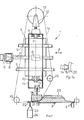
- the grinding device 1 essentially consists of a support 4, which is slidably supported by horizontally arranged parallel guides 5.
- the guides 5 are firmly connected to the machine frame (not shown).
- a precision threaded nut 6 is attached to the support 4.
- the nut 6 is operatively connected to a highly precise threaded spindle 7, advantageously with a recirculating ball screw.
- the threaded spindle 7 is arranged parallel to the horizontally arranged guides 5 and connected to the drive shaft of a spreadable motor 8.
- a known controllable DC motor is advantageously used, to which, for example, a control device 9 known from the prior art is assigned.
- the support 4 can be given a translational movement in the direction of the arrow f.
- From the support 4 there are horizontally arranged arms 10 which carry a further support 11 which can be pivoted about one Vertical axis z is mounted.
- the support 11 receives a bearing block 12, which receives a deflection roller 13, around which a grinding belt 14 rotates.
- the sanding belt 14 is also steered around a guide roller 15 which is arranged to be adjustable in the vertical direction, and also, the sanding belt 14 runs around a guide roller 16 which is adjustable in the horizontal direction.
- the support 11 On its underside, the support 11 receives a small control cylinder 17, advantageously a controllable pneumatic cylinder, which is operatively connected to a grinding shoe 19 via its piston rod 18.
- the grinding shoe 19 has the shape of the profile to be ground (seen in section) of the plate-shaped workpiece 20. From Fig. 1a it can be seen that the grinding shoe 19 has a trapezoidal shape, i.e. that it tapers wedge-shaped towards workpiece 20. This measure ensures that the grinding belt 14 is properly guided, and at the same time it is possible to use the narrow front of the grinding shoe to also drive relatively tight curves of the profile profile.
- the workpiece 20 is moved forward by the conveyor belt 2 perpendicular to the plane of the drawing (FIG. 1).
- the workpiece is held in a precisely defined reference position with respect to the workpiece 20 by the guide rollers 3.
- the biaxial copying device is of type CPE and is in all its technical details, together with the electronic data processing unit and signal control device, as well as the corresponding electronic connection or connection plates (interfaces), which are absolutely necessary for the connection of the electronic button, from the catalog of Fadis SpA - Divisione Automatismi, based in 21048 Solbiate Arno (Italy).
- This company offers the described scanning and control device and sells these devices on the Italian and international market.
- the exact description of the button and the associated control device is therefore omitted, since these components are known from the prior art.
- Fig. 2 From Fig. 2 it can be seen that the entire. Grinding device 1 is received by the machine frame 25 in a height-adjustable manner.
- a dovetail guide 26 common in mechanical engineering is advantageously provided, which allows the belt grinding device 1 to be displaced and adjusted relative to the reference plane of the conveyor belt 2 or of the workpiece 20.
- the holding arm 10 which is operatively connected to the support 4 and receives the support 11 rotatable about the vertical axis Z, also carries a controllable motor, advantageously a direct current motor 27.
- This motor 27 is located above a reduction gear 28, the output shaft of which receives a chain wheel 29 , with another sprocket 31 via a chain 30 in operative connection.
- the sprocket 31 is operatively connected to the inside of the support 11 so that the support 11 can be pivoted in the direction of the arrow g (FIG. 2) about the Z axis.
- the deflection roller 13, which receives the grinding belt 14, is driven by a motor 32 (FIG. 2). 2, the adjustable front guide roller 15 can also be seen.
- the plate-shaped workpieces 20 are moved in the direction of arrow h by the conveyor belt 2.
- Fig. 3 the control circuit for the motor 8 is shown schematically.
- the motor 8 is provided for the displacement of the grinding device 4 in a horizontal plane.
- the feeler wheel 22 is in contact with the edge 21 of the plate-shaped workpiece 20 and is fastened to the feeler rod 23 of the electronic, biaxial copying device or feeler device 24.
- the signal outputs of the scanning device 24 are connected via one or more lines 33 to an electronic evaluation and control unit 34 (NC unit).
- the output of the control unit 34 is via a Line 35 with the input of the control device 9 in operative connection, and this control device 9 is assigned to the controllable DC motor 8, which drives the threaded spindle 7, which is operatively connected to the threaded nut 6, which in turn is attached to the support 4.
- a recording device 36 can also be provided, with which, for example, the signals emitted by the electronic, biaxial button 24 when a workpiece 20 is moved are stored. These signals are recorded, for example, by means of a magnetic tape cassette or a similar recording device, and are used for the purposes explained later.
- the threaded nut 6 is also operatively connected to the electronic, biaxial button 24 via a line 36, so that, with the aid of known transmission means, the scanning device is informed of the exact, actual position of the threaded nut 6.
- a further output of the electronic, biaxial button 24 is connected via a line 37 to a further input of the electronic control and processing unit 34.
- the corresponding output signal of the unit 34 is fed via a line 38 to the controllable motor 27, the drive shaft of which, with the interposition of a reduction gear 28, is operatively connected to the chain wheel 29.
- the sprocket 29 takes the chain 30, which is operatively connected to the sprocket 31, which is attached to the support 11, which is pivotally mounted about the vertical axis Z.
- a rotary potentiometer 39 is also provided, for example, which, in accordance with its angular position, emits a signal which is forwarded to the electronic control unit 34 via a line 40 as an effective angular position value.
- the control unit 34 uses this signal as a reference signal for the position of the shaft 27 of the motor 27, which receives the chain wheel 29, and thus represents a reference value for the angular position of the grinding unit 11, which can be pivoted about the vertical axis Z via the drive of the chain wheel 31 .
- FIG. 5 again shows schematically the possibility of pivoting the grinding device 11 about the axis Z; furthermore, the sprocket 29 can be seen from this illustration is provided for driving the chain 30, which is operatively connected to the chain wheel 31, and for pivoting the grinding device 11 (represented by the grinding belt 14) about the vertical axis Z.
- the grinding roller 50 has a counter profile 52 which corresponds to the profile piece 53 to be ground.
- the grinding roller 50 is advantageously made of elastic, abrasive material and is rotated by means of a vertically arranged shaft 51 and is also adjustable relative to the profile piece 53.
- a grinding roller or disc rotating about a horizontally arranged shaft can of course also be used.
- the position of the roller 50 relative to the workpiece 20 can also be adjusted with the aid of the button 23, 24, which acts on the controllable motors 8, 27.
- the workpiece 20 to be ground which is fed through the conveyor belt 2 to the grinding device, with the aid of the guide rollers 54 (Fig. 7-8), which are arranged on the opposite side of the button 24 of the conveyor belt 2, set.
- the guide rollers 54 are adjustable according to the dimensions of the workpiece 20.
- the push buttons 22, 23, 24 are in a "zero position", ie no control signals are emitted by the push button unit 24, since the push button is exactly at the intersection of the axes X, Y (FIG. 4 a) located.
- the pushbutton 23 is deflected in the direction of the axes X and Y, and control signals are emitted via the pushbutton unit 24, corresponding to the deflection of the pushbutton, and 3 and 4, these signals are fed to the control circuits, as a result of which a controlled drive of the motor 8 (displacement of the support 4 on the horizontal guides 5) and, with the aid of the controllable motor 27, a pivoting of the grinding device 11 about the vertical axis Z of the Unit 11 takes place.
- the plate-shaped feed path is particularly advantageous Workpieces 20, an actuatable switch 55 or a similar control means are arranged, which notifies the electronic control unit 34 of the supply of a plate-shaped workpiece 20, as a result of which the control unit 34 can emit corresponding delay signals or control pulses in order, for example, to lift or lift the piston unit 17, 18 to control the lowering of the grinding shoe 19 in order to start grinding or lifting the grinding belt exactly at the desired location without damaging the workpiece or not grinding completely.
- the button 22, 23, which is connected to the profile edge 21, is deflected.
- the deflection takes place in the direction of the axes X, Y, corresponding to the curved course of the profiled edge 21, and thus there is a constant displacement of the grinding shoe 19 with respect to the curved and profiled edge 21 and at the same time there is a superimposition of a pivoting movement of the grinding shoe 19 about the vertical axis Z, thereby always ewaehrologicalt g, d ass grinding belt 14 and sanding shoe are always aligned tangentially to the 19 course of the curving of the profiled edge 21st In other words, the grinding belt 14 always works in the longitudinal direction of the wood fiber.
- the button 22, 23 is moved back to its "zero position" after completion of the grinding process either with the aid of a spring means or other suitable devices, as a result of which both the device 4 and the device 11 are moved back to their original position and thus are ready to be controlled again in order to subject the subsequent plate-shaped workpiece 20 to the grinding process.
- the grinding device With the grinding device according to the invention, it has become possible to propose a device which for the first time can carry out automatic grinding, using a grinding belt, of continuously fed and moving workpieces with profiled and curved edges. It will be possible for the first time on the so far to dispense with the necessary finishing by hand of these profiled and curved edges.
- the sanding process always takes place in the ideal way in the direction of the wood grain, and it is not necessary to adjust the sanding device to the workpiece, taking into account the profile profile. This is done automatically.
- the device according to the invention can also be installed as an additional unit in already existing machines which are used for machining plate-shaped workpieces.
- machines which are used for machining plate-shaped workpieces.
- Double end profiles and especially edge banding machines are considered.
- control signals for certain types of profiles can be recorded and stored, and in this case the grinding device can also be controlled directly via the recorded control signals without a button.
Landscapes
- Engineering & Computer Science (AREA)
- Mechanical Engineering (AREA)
- Finish Polishing, Edge Sharpening, And Grinding By Specific Grinding Devices (AREA)
- Grinding And Polishing Of Tertiary Curved Surfaces And Surfaces With Complex Shapes (AREA)
Applications Claiming Priority (2)
| Application Number | Priority Date | Filing Date | Title |
|---|---|---|---|
| IT21972/81A IT1137230B (it) | 1981-05-26 | 1981-05-26 | Gruppo di levigatura a nastro,per pannelli con bordi profilati e sagomati |
| IT2197281 | 1981-05-26 |
Publications (2)
| Publication Number | Publication Date |
|---|---|
| EP0065769A2 true EP0065769A2 (fr) | 1982-12-01 |
| EP0065769A3 EP0065769A3 (fr) | 1983-04-06 |
Family
ID=11189595
Family Applications (1)
| Application Number | Title | Priority Date | Filing Date |
|---|---|---|---|
| EP82104456A Withdrawn EP0065769A3 (fr) | 1981-05-26 | 1982-05-21 | Dispositif de meulage pour l'usinage de pièces en forme de plaques avec des arêtes profilées et incurvées |
Country Status (4)
| Country | Link |
|---|---|
| EP (1) | EP0065769A3 (fr) |
| JP (1) | JPS584348A (fr) |
| ES (1) | ES8306627A1 (fr) |
| IT (1) | IT1137230B (fr) |
Cited By (8)
| Publication number | Priority date | Publication date | Assignee | Title |
|---|---|---|---|---|
| EP0455142A3 (en) * | 1990-04-25 | 1992-04-29 | Reko Maschinenbau Gmbh | Profil grinding machine |
| DE4241293A1 (de) * | 1992-12-08 | 1994-06-09 | Stahl Sm Maschf | Oberflächenbearbeitungsmaschine |
| CN107627180A (zh) * | 2017-09-19 | 2018-01-26 | 东莞艾法精密机械有限公司 | 一种边角打磨机 |
| CN110405578A (zh) * | 2019-08-01 | 2019-11-05 | 常熟市益诚精密机械有限公司 | 一种电脑横机配件加工用打磨装置 |
| CN112296804A (zh) * | 2020-10-14 | 2021-02-02 | 李宁 | 一种装饰用木柜边角磨平装置 |
| CN113458929A (zh) * | 2021-07-13 | 2021-10-01 | 京东方科技集团股份有限公司 | 应用于盖板内表面的加工设备、盖板及显示设备 |
| CN116967907A (zh) * | 2023-09-21 | 2023-10-31 | 山西一建集团有限公司 | 一种铝镁锰墙板施工用表面杂质处理装置 |
| CN118322306A (zh) * | 2024-05-15 | 2024-07-12 | 佛山市顺德区红力机械设备有限公司 | 一种板材边缘油漆涂边填充方法 |
Families Citing this family (4)
| Publication number | Priority date | Publication date | Assignee | Title |
|---|---|---|---|---|
| JPS60167756A (ja) * | 1984-02-08 | 1985-08-31 | Shigeru Hasegawa | 木工用サンダ− |
| JPS60157158U (ja) * | 1984-03-30 | 1985-10-19 | 長谷川 茂 | 木工用サンダ− |
| JPS60157157U (ja) * | 1984-03-30 | 1985-10-19 | 長谷川 茂 | 木工用サンダ− |
| CN111941228B (zh) * | 2020-07-07 | 2022-02-08 | 湖南工程学院 | 一种手持式家具板材边端毛刺处理装置 |
Family Cites Families (8)
| Publication number | Priority date | Publication date | Assignee | Title |
|---|---|---|---|---|
| DE499283C (de) * | 1927-07-19 | 1930-06-10 | Herzogenrather Glaswerke Biche | Vorrichtung zum Schleifen von Fassettenflaechen mit gerader Erzeugenden und ungerader Leitlinie |
| AT269455B (de) * | 1964-08-18 | 1969-03-25 | Zuckermann Kg Maschf | Kopiermaschine für Formteile aus Holz |
| AT266423B (de) * | 1966-02-25 | 1968-11-11 | Zuckermann Komm Ges Wien Masch | Kopiermaschine zum Längsbearbeiten von Werkstücken aus Holz |
| SE314496B (fr) * | 1967-12-18 | 1969-09-08 | Wst Patenter Ab | |
| DE6905417U (de) * | 1969-02-10 | 1969-08-07 | Richard Staehle Kg Maschb Fa | Schleifschuh mit keramischer druckplatte, insbesondere fuer bandschleifmaschinen. |
| US3673737A (en) * | 1970-05-04 | 1972-07-04 | Libbey Owens Ford Co | Sheet edging apparatus |
| US3779294A (en) * | 1972-03-27 | 1973-12-18 | Mill And Timber Products Ltd | Board edging machine |
| AT313096B (de) * | 1972-06-27 | 1974-01-25 | Zuckermann Komm Ges Wien Masch | Maschine zum Schleifen der profilierten Sitzfläche von Sitzplatten u.dgl. hölzernen Möbelteilen |
-
1981
- 1981-05-26 IT IT21972/81A patent/IT1137230B/it active
-
1982
- 1982-05-21 EP EP82104456A patent/EP0065769A3/fr not_active Withdrawn
- 1982-05-25 ES ES513329A patent/ES8306627A1/es not_active Expired
- 1982-05-26 JP JP57089586A patent/JPS584348A/ja active Pending
Cited By (11)
| Publication number | Priority date | Publication date | Assignee | Title |
|---|---|---|---|---|
| EP0455142A3 (en) * | 1990-04-25 | 1992-04-29 | Reko Maschinenbau Gmbh | Profil grinding machine |
| DE4241293A1 (de) * | 1992-12-08 | 1994-06-09 | Stahl Sm Maschf | Oberflächenbearbeitungsmaschine |
| DE4241293C3 (de) * | 1992-12-08 | 1999-12-16 | Stahl Sm Maschf | Maschine zur Oberflächenbearbeitung von Werkstücken, insbesondere Bandschleifmaschine |
| CN107627180A (zh) * | 2017-09-19 | 2018-01-26 | 东莞艾法精密机械有限公司 | 一种边角打磨机 |
| CN110405578A (zh) * | 2019-08-01 | 2019-11-05 | 常熟市益诚精密机械有限公司 | 一种电脑横机配件加工用打磨装置 |
| CN112296804A (zh) * | 2020-10-14 | 2021-02-02 | 李宁 | 一种装饰用木柜边角磨平装置 |
| CN113458929A (zh) * | 2021-07-13 | 2021-10-01 | 京东方科技集团股份有限公司 | 应用于盖板内表面的加工设备、盖板及显示设备 |
| CN113458929B (zh) * | 2021-07-13 | 2022-12-27 | 京东方科技集团股份有限公司 | 应用于盖板内表面的加工设备、盖板及显示设备 |
| CN116967907A (zh) * | 2023-09-21 | 2023-10-31 | 山西一建集团有限公司 | 一种铝镁锰墙板施工用表面杂质处理装置 |
| CN116967907B (zh) * | 2023-09-21 | 2023-12-19 | 山西一建集团有限公司 | 一种铝镁锰墙板施工用表面杂质处理装置 |
| CN118322306A (zh) * | 2024-05-15 | 2024-07-12 | 佛山市顺德区红力机械设备有限公司 | 一种板材边缘油漆涂边填充方法 |
Also Published As
| Publication number | Publication date |
|---|---|
| ES513329A0 (es) | 1983-06-01 |
| EP0065769A3 (fr) | 1983-04-06 |
| IT8121972A0 (it) | 1981-05-26 |
| JPS584348A (ja) | 1983-01-11 |
| IT1137230B (it) | 1986-09-03 |
| ES8306627A1 (es) | 1983-06-01 |
Similar Documents
| Publication | Publication Date | Title |
|---|---|---|
| DE69905305T2 (de) | Kantenleimgerät | |
| EP0065769A2 (fr) | Dispositif de meulage pour l'usinage de pièces en forme de plaques avec des arêtes profilées et incurvées | |
| DE3420080C1 (de) | Abbundmaschine zum Bearbeiten von Brettern,Kanthoelzern und dergleichen | |
| DE2756443C3 (de) | Anlage zum automatischen Schleifen der Kanten von Glasscheiben | |
| DE3424258C2 (de) | Maschine zum Kantenschleifen von Glasscheiben | |
| EP0654333A1 (fr) | Machine à travailler des pièces à usiner en bois, plastique ou similaires | |
| EP0596083B1 (fr) | Dispositif a meuleuse fonctionnant transversalement au sens de passage des pieces et son utilisation dans le meulage de cadres | |
| DE2723231B2 (de) | Maschine zum Abrunden mit einem vorbestimmten Radius der Ecken von Glasplatten | |
| DE2614843C2 (de) | Kopierschleifmaschine | |
| DE3533185A1 (de) | Glasplatten-schleifmaschine | |
| DE3876857T2 (de) | Vorrichtung zum automatischen schleifen der abgerundeten ecken von platten. | |
| DE2635473A1 (de) | Schleifbandumlenkung fuer querbandschleifmaschinen | |
| DE2523110A1 (de) | Furnierzusammensetzmaschine | |
| EP1105266A1 (fr) | Machine servant a placer un bord de chant comportant un profile de fixation | |
| DE2947039C2 (fr) | ||
| DE2846238C2 (de) | Zusatzeinrichtung zum Bürsten ebener Werkstücke mit Naturholzoberfläche | |
| DE2204216B2 (de) | Vorrichtung fuer das fraesen eines laengsprofils in laengsbewegte werkstuecke | |
| DE3546491A1 (de) | Glasplatten-schleifmaschine | |
| DE1652386A1 (de) | Kopiermaschine zum Laengsbearbeiten von Werkstuecken aus Holz | |
| DE2151154A1 (de) | Vorrichtung zum verbinden von furnierblaettern | |
| DE2017440C3 (de) | Fräsmaschine zum Bearbeiten von Profilflächen | |
| DE3716832A1 (de) | Verfahren zum betrieb einer bandschleifmaschine sowie bandschleifmaschine | |
| DE191756C (fr) | ||
| DE2952012A1 (de) | Andrueckvorrichtung fuer kantenumleimer | |
| DE4319276A1 (de) | Verfahren zum automatischen Polieren von Flachkanten an Platten aus Marmor, Naturstein, Granit und desgleichen und Poliermaschine zur Durchführung dieses Verfahrens |
Legal Events
| Date | Code | Title | Description |
|---|---|---|---|
| PUAI | Public reference made under article 153(3) epc to a published international application that has entered the european phase |
Free format text: ORIGINAL CODE: 0009012 |
|
| AK | Designated contracting states |
Designated state(s): AT CH DE FR GB LI SE |
|
| PUAL | Search report despatched |
Free format text: ORIGINAL CODE: 0009013 |
|
| AK | Designated contracting states |
Designated state(s): AT CH DE FR GB LI SE |
|
| 17P | Request for examination filed |
Effective date: 19831006 |
|
| STAA | Information on the status of an ep patent application or granted ep patent |
Free format text: STATUS: THE APPLICATION IS DEEMED TO BE WITHDRAWN |
|
| 18D | Application deemed to be withdrawn |
Effective date: 19850104 |
|
| RIN1 | Information on inventor provided before grant (corrected) |
Inventor name: STEFANI, GIORGIO |