EP0596083B1 - Dispositif a meuleuse fonctionnant transversalement au sens de passage des pieces et son utilisation dans le meulage de cadres - Google Patents
Dispositif a meuleuse fonctionnant transversalement au sens de passage des pieces et son utilisation dans le meulage de cadres Download PDFInfo
- Publication number
- EP0596083B1 EP0596083B1 EP93911716A EP93911716A EP0596083B1 EP 0596083 B1 EP0596083 B1 EP 0596083B1 EP 93911716 A EP93911716 A EP 93911716A EP 93911716 A EP93911716 A EP 93911716A EP 0596083 B1 EP0596083 B1 EP 0596083B1
- Authority
- EP
- European Patent Office
- Prior art keywords
- sanding
- longitudinal
- slat
- transverse
- grinding
- Prior art date
- Legal status (The legal status is an assumption and is not a legal conclusion. Google has not performed a legal analysis and makes no representation as to the accuracy of the status listed.)
- Expired - Lifetime
Links
- 238000000034 method Methods 0.000 claims description 8
- 239000000463 material Substances 0.000 abstract description 2
- 230000001680 brushing effect Effects 0.000 abstract 1
- 238000005259 measurement Methods 0.000 abstract 1
- 230000000694 effects Effects 0.000 description 3
- 239000000523 sample Substances 0.000 description 2
- 230000007704 transition Effects 0.000 description 2
- 239000002023 wood Substances 0.000 description 2
- 229920002522 Wood fibre Polymers 0.000 description 1
- 238000010276 construction Methods 0.000 description 1
- 230000011218 segmentation Effects 0.000 description 1
- 230000001960 triggered effect Effects 0.000 description 1
- 239000002025 wood fiber Substances 0.000 description 1
Images


Classifications
-
- B—PERFORMING OPERATIONS; TRANSPORTING
- B24—GRINDING; POLISHING
- B24B—MACHINES, DEVICES, OR PROCESSES FOR GRINDING OR POLISHING; DRESSING OR CONDITIONING OF ABRADING SURFACES; FEEDING OF GRINDING, POLISHING, OR LAPPING AGENTS
- B24B21/00—Machines or devices using grinding or polishing belts; Accessories therefor
- B24B21/04—Machines or devices using grinding or polishing belts; Accessories therefor for grinding plane surfaces
- B24B21/06—Machines or devices using grinding or polishing belts; Accessories therefor for grinding plane surfaces involving members with limited contact area pressing the belt against the work, e.g. shoes sweeping across the whole area to be ground
-
- B—PERFORMING OPERATIONS; TRANSPORTING
- B24—GRINDING; POLISHING
- B24B—MACHINES, DEVICES, OR PROCESSES FOR GRINDING OR POLISHING; DRESSING OR CONDITIONING OF ABRADING SURFACES; FEEDING OF GRINDING, POLISHING, OR LAPPING AGENTS
- B24B7/00—Machines or devices designed for grinding plane surfaces on work, including polishing plane glass surfaces; Accessories therefor
- B24B7/20—Machines or devices designed for grinding plane surfaces on work, including polishing plane glass surfaces; Accessories therefor characterised by a special design with respect to properties of the material of non-metallic articles to be ground
- B24B7/28—Machines or devices designed for grinding plane surfaces on work, including polishing plane glass surfaces; Accessories therefor characterised by a special design with respect to properties of the material of non-metallic articles to be ground for grinding wood
Definitions
- the present invention relates to a working transverse to its direction of travel Device and its use such that when combined with conventional Grinding machines transverse to each other, connected parts of frames and frame-like Workpieces are ground in a single pass in their own longitudinal direction.
- Such a device is known from JP-A-59-115 155.
- Cross-sanding unit 37 Although they are pre-built Cross-sanding unit 37 provided, but since with the usual construction of frames (for example windows) the transverse friezes 32, 24 are inserted between the longitudinal friezes 27, 35 the cross friezes, even with perfect pre-grinding, would be replaced by the following Broadband smoothed again across their orientation. If you gave the frame across, i.e. with the width 27 ahead, into the machine, this problem would be eliminated (because with the Cross sanding unit would grind the longitudinal friezes, the cross friezes would follow sanded with insert-controlled broad belts), but usually allows the working width the machine does not cross the frame. Another one that is not familiar in practice The method of operation would be to close the cross-grinding unit at the outlet of the grinding machine assemble.
- the whole frame would be sanded with the broad bands the cross frieze finally (with the same grain size) regrind at the outlet with the cross sanding belt. Because of the one pass (because of the previously mentioned restrictions regarding working width) the cross friezes lie in the longitudinal direction of the frame again between the friezes. The latter would therefore have to be mission-controlled (from one Transition transverse to longitudinal frieze to the other transition). Suitable for this however, the previously used operational control of the cross-section unit does not exist in that individual segments 40 of a continuous sanding pad 39 the cross sanding belt press on the area to be sanded.
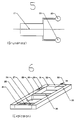
- the present invention now describes a device in which the frames are initially guided on a transport carpet 13 through an automatic thickness adjustment 11 measuring over the entire working width.
- this defines the height of the transport table (depending on the workpiece thickness determined) compared to a subsequent, longitudinally movable, driven carriage 14 guided on both sides, which is equipped with a belt grinding unit 15 mounted transversely to the direction of travel.
- the automatic setting triggers a pulse control when the workpiece leading edge passes. This controls the use of the slide by calculating the feed speed. If the cross frieze 32 is at the level of the latter, the slide starts to move and accompanies the workpiece.
- the abrasive pad 17 on the carriage and belonging to the belt sanding unit starts to move transversely to the direction of travel. If the sensor 22 connected to the sanding pad (in front of the sanding pad in the side axis, set back in the longitudinal axis) detects the lateral outer edge 30 of the frame, it brakes (and with it the entire sanding pad) and scans the width of the longitudinal frieze at a slow speed.
- the sanding pad When the inner edge 31 is reached, the sanding pad is set down, this accelerates, driven by a motor to a linear working speed, and presses the sanding belt 18 on the device pneumatically to the actual sanding process on the transverse frieze 32 , he brakes the cushion, stops the grinding process and the cushion returns at high speed to a position between the starting position and the front longitudinal frieze 27. At the same time, the carriage 14 also moves back to its starting position with the belt grinding unit 15.
- the cushion in turn moves to the frieze outer edge 30, which is detected by a second sensor 23 (placed in front of the grinding cushion in the lateral and longitudinal axes); the cushion probes with the help of the sensor to the inner edge 31, where it settles on the belt 18 and grinds the second cross frieze 24.
- the second sensor 23 detects the rear inner edge 33 of the longitudinal frieze, the cushion slows down, stops and moves back to the starting position at accelerated speed.
- the carriage 14 also moves back to its starting position with the belt grinding unit 15. If the frame contains one or more middle friezes 36, this is ascertained with the button 12 at the inlet and an additional, similar transverse movement is triggered.
- this device is combined with a broadband grinding machine 41 or integrated into this (the measuring device 11 can be built in front of the broadband grinding machine and serves to control both systems), the latter will initially grind the entire frame in the longitudinal direction. The device described will then regrind the cross friezes in their own direction 25 (in the case of wood: in the wood fiber direction) and achieve the desired sanding pattern.
- the device described instead of the belt sanding unit and the sanding pad is equipped with another device for sanding (e.g. with a surface or profile sanding unit 21 that carries the sanding belt), with brushes 20, fleece or tools with a similar function, the corresponding surface-effective effects can be achieved in this way achieve that they follow the Frisians in their own longitudinal direction.
- the device according to claim 7 also serves internal profiles 28 (such as rebates etc.) of frames.
- the implement for example a brush with Sanding bristles, with fleece or materials with a similar effect
- the device instead of reaching the inner edge of the rear frieze to expose (like this with surface grinding in combination with the conventional grinding machine is the case), the device remains in its end position and processed during this operation the frame advancing on the transport carpet on the inner profile of the longitudinal frieze. It only stops when the inside edge of the second cross frieze is reached.
- two such devices a first first the cross frieze profile 32 and then the longitudinal frieze profile 35 and a second processed the other longitudinal frieze profile 27 and then the rear cross frieze profile 24
- the entire inner profile of a frame can be processed in a single pass.
Landscapes
- Engineering & Computer Science (AREA)
- Mechanical Engineering (AREA)
- Life Sciences & Earth Sciences (AREA)
- Wood Science & Technology (AREA)
- Finish Polishing, Edge Sharpening, And Grinding By Specific Grinding Devices (AREA)
- Grinding Of Cylindrical And Plane Surfaces (AREA)
- Polishing Bodies And Polishing Tools (AREA)
Claims (2)
- Dispositif destiné à meuler des pièces semblables à des cadres, munies de frises longitudinales (27, 35) et transversales (24, 32), intégrant un système de ponçage à bande abrasive fonctionnant transversalement par rapport au sens continu de la pièce, lequel dispositif constitue une unité fermée composée d'une table porte-pièce avec bande transporteuse (13), d'un chariot (14) se déplaçant dans le sens continu de la pièce ainsi que d'un système de ponçage à bande abrasive (15) entraíné par le chariot (14) et équipé d'un coussin à meuler à déplacement transversal (17),
se caractérisant par le fait que,
ledit dispositif comprend un équipement de mesure (11), un palpeur (12) destiné à bloquer les frises transversales (24, 32) et un capteur (22) relié au coussin à meuler (17) pour identification des arêtes latérales (27, 35) ; lors de l'identification de l'arête latérale extérieure d'une frise longitudinale, le coussin à meuler (17) fixé en mouvement rapide à partir d'une position initiale se trouve freiné et la largeur de la frise longitudinale (27, 35) est balayée à vitesse plus lente, le processus de meulage d'une frise transversale étant déclenché lorsque l'arête intérieure (31) de la frise longitudinale est atteinte et ledit processus de meulage étant stoppé lorsqu'une arête intérieure opposée (33) d'une frise longitudinale est identifiée, le coussin à meuler (17) étant par ailleurs remis à grande vitesse en position, entre la position initiale et la frise longitudinale avant. - Dispositif destiné à meuler des pièces semblables à des cadres, munies de frises longitudinales (27, 35) et transversales (24, 32), intégrant un système de ponçage fonctionnant transversalement par rapport au sens continu de la pièce, lequel dispositif constitue une unité fermée composée d'une table porte-pièce avec bande transporteuse (13), d'un chariot (14) se déplaçant dans le sens continu de la pièce ainsi que d'un système de ponçage à déplacement transversal entraíné par le chariot (14),
se caractérisant par le fait que,
ledit dispositif comprend un équipement de mesure (11), un palpeur (12) destiné à bloquer les frises transversales (24, 32) et un capteur (22) relié au système de ponçage pour identification des arêtes latérales des frises longitudinales (27, 35) ; lors de l'identification de l'arête latérale extérieure d'une frise longitudinale, le système de ponçage fixé en mouvement rapide à partir d'une position initiale se trouve freiné et la largeur de la frise longitudinale (27, 35) est balayée à vitesse plus lente, le processus de meulage d'une frise transversale étant déclenché lorsque l'arête intérieure (31) de la frise longitudinale est atteinte et ledit processus de meulage étant stoppé lorsqu'une arête intérieure opposée (33) d'une frise longitudinale est identifiée, le système de ponçage étant par ailleurs remis à grande vitesse en position, entre la position initiale et la frise longitudinale avant.
Applications Claiming Priority (3)
| Application Number | Priority Date | Filing Date | Title |
|---|---|---|---|
| CH159292 | 1992-05-19 | ||
| CH1592/92 | 1992-05-19 | ||
| PCT/CH1993/000117 WO1993023203A1 (fr) | 1992-05-19 | 1993-05-10 | Dispositif a meuleuse fonctionnant transversalement au sens de passage des pieces et son utilisation dans le meulage de cadres |
Publications (2)
| Publication Number | Publication Date |
|---|---|
| EP0596083A1 EP0596083A1 (fr) | 1994-05-11 |
| EP0596083B1 true EP0596083B1 (fr) | 1998-01-21 |
Family
ID=4214024
Family Applications (1)
| Application Number | Title | Priority Date | Filing Date |
|---|---|---|---|
| EP93911716A Expired - Lifetime EP0596083B1 (fr) | 1992-05-19 | 1993-05-10 | Dispositif a meuleuse fonctionnant transversalement au sens de passage des pieces et son utilisation dans le meulage de cadres |
Country Status (6)
| Country | Link |
|---|---|
| EP (1) | EP0596083B1 (fr) |
| JP (1) | JPH06508073A (fr) |
| AT (1) | ATE162448T1 (fr) |
| CA (1) | CA2113427A1 (fr) |
| DE (1) | DE59308034D1 (fr) |
| WO (1) | WO1993023203A1 (fr) |
Families Citing this family (9)
| Publication number | Priority date | Publication date | Assignee | Title |
|---|---|---|---|---|
| ITMI20020033A1 (it) * | 2002-01-10 | 2002-12-03 | Marino Angeloni | Macchina per carteggiare manufatti iano sagomati |
| US7052380B2 (en) * | 2003-12-19 | 2006-05-30 | Georg Weber | Sanding station for a belt sanding machine |
| DE202005014430U1 (de) * | 2005-09-12 | 2005-11-24 | Lissmac Maschinenbau Und Diamantwerkzeuge Gmbh | Vorrichtung zum Bearbeiten eines Werkstücks |
| AT516183B1 (de) * | 2014-10-06 | 2016-03-15 | Berndorf Band Gmbh | Verfahren zum Schleifen einer Schweißnaht eines Metallbands |
| EP3508305A1 (fr) * | 2018-01-09 | 2019-07-10 | SRL Volpato | Triangle ponceuse à bande avec engrenage angulaire |
| CH716746A2 (de) * | 2019-10-16 | 2021-04-30 | Kuendig Ag | Vorrichtung und Verfahren für den seitlich präzis definierten Einsatz von Schleifbändern bei Bandschleifmaschinen im Durchlauf. |
| CN112476180B (zh) * | 2020-11-25 | 2023-06-02 | 浙江荣涛家具有限公司 | 一种加工用家具砂布床 |
| CN114643502B (zh) * | 2022-04-27 | 2023-04-14 | 东莞市鹏宇电子设备有限公司 | 一种全自动磨板机设备 |
| CN115351657A (zh) * | 2022-08-31 | 2022-11-18 | 桂林航天工业学院 | 一种智能拉丝机 |
Family Cites Families (1)
| Publication number | Priority date | Publication date | Assignee | Title |
|---|---|---|---|---|
| DE3426595A1 (de) * | 1984-07-19 | 1986-01-30 | Paul Ing.(grad.) 6925 Eschelbronn Ernst | Vorrichtung zum schleifen von rahmenartigen werkstuecken |
-
1993
- 1993-05-10 WO PCT/CH1993/000117 patent/WO1993023203A1/fr not_active Ceased
- 1993-05-10 DE DE59308034T patent/DE59308034D1/de not_active Expired - Fee Related
- 1993-05-10 JP JP5519743A patent/JPH06508073A/ja active Pending
- 1993-05-10 AT AT93911716T patent/ATE162448T1/de not_active IP Right Cessation
- 1993-05-10 EP EP93911716A patent/EP0596083B1/fr not_active Expired - Lifetime
- 1993-05-10 CA CA002113427A patent/CA2113427A1/fr not_active Abandoned
Also Published As
| Publication number | Publication date |
|---|---|
| EP0596083A1 (fr) | 1994-05-11 |
| ATE162448T1 (de) | 1998-02-15 |
| JPH06508073A (ja) | 1994-09-14 |
| WO1993023203A1 (fr) | 1993-11-25 |
| CA2113427A1 (fr) | 1993-11-20 |
| DE59308034D1 (de) | 1998-02-26 |
Similar Documents
| Publication | Publication Date | Title |
|---|---|---|
| DE60005749T2 (de) | Doppelseitige Kantenschleifmaschine für glas- oder steinartiges Flachmaterial und desgleichen | |
| EP2384853A1 (fr) | Meuleuse à double face | |
| DE3736706C2 (de) | Schleifmaschine zum Feinschleifen von Schneidwerkzeugen mit geradliniger Schneidkante | |
| WO1993023203A1 (fr) | Dispositif a meuleuse fonctionnant transversalement au sens de passage des pieces et son utilisation dans le meulage de cadres | |
| EP0065769A2 (fr) | Dispositif de meulage pour l'usinage de pièces en forme de plaques avec des arêtes profilées et incurvées | |
| DE60305461T2 (de) | Automatisierte verarbeitungseinheit für eine arbeitsstation | |
| DE19821982C2 (de) | Profil-Bandschleifmaschine | |
| DE1258309B (de) | Doppelseitige Laengskopiermaschine fuer die Herstellung von Formteilen, insbesondere von Massivholzteilen | |
| DE2948719A1 (de) | Messerwalzen-maschine zur bearbeitung von haeuten und fellen | |
| DE20108243U1 (de) | Vorrichtung zum Versäubern von plattenförmigen, beschichteten Werkstücken | |
| DE2635473A1 (de) | Schleifbandumlenkung fuer querbandschleifmaschinen | |
| DE2614843B1 (de) | Kopierschleifmaschine | |
| DE19602934C2 (de) | Lackzwischenschleifanlage | |
| EP0625407B1 (fr) | Pongeuse | |
| DE2846238C2 (de) | Zusatzeinrichtung zum Bürsten ebener Werkstücke mit Naturholzoberfläche | |
| EP1629941B1 (fr) | Procédé pour ébavurer et/ou améliorer la surface de pièces usinées | |
| DE4017991C2 (fr) | ||
| EP1743737A1 (fr) | Ponceuse au défilé pour traiter une pièce en surface plane | |
| DE3716832C2 (de) | Druckbalken für eine Bandschleifmaschine | |
| DE933782C (de) | Bandschleifmaschine, insbesondere Profil- und Kantenschleifmaschine | |
| DE1281302B (de) | Knueppelschleifmaschine | |
| DE102004041134A1 (de) | Vorrichtung zum Entgraten und/oder Oberflächenverbessern von spanend bearbeiteten Werkstücken | |
| DE20120999U1 (de) | Schleifmaschine | |
| DE3639598C1 (en) | Device for processing the cut surfaces of split tiles | |
| CH716746A2 (de) | Vorrichtung und Verfahren für den seitlich präzis definierten Einsatz von Schleifbändern bei Bandschleifmaschinen im Durchlauf. |
Legal Events
| Date | Code | Title | Description |
|---|---|---|---|
| PUAI | Public reference made under article 153(3) epc to a published international application that has entered the european phase |
Free format text: ORIGINAL CODE: 0009012 |
|
| 17P | Request for examination filed |
Effective date: 19940104 |
|
| AK | Designated contracting states |
Kind code of ref document: A1 Designated state(s): AT CH DE FR GB IT LI |
|
| 17Q | First examination report despatched |
Effective date: 19950714 |
|
| GRAG | Despatch of communication of intention to grant |
Free format text: ORIGINAL CODE: EPIDOS AGRA |
|
| GRAG | Despatch of communication of intention to grant |
Free format text: ORIGINAL CODE: EPIDOS AGRA |
|
| GRAH | Despatch of communication of intention to grant a patent |
Free format text: ORIGINAL CODE: EPIDOS IGRA |
|
| GRAH | Despatch of communication of intention to grant a patent |
Free format text: ORIGINAL CODE: EPIDOS IGRA |
|
| GRAA | (expected) grant |
Free format text: ORIGINAL CODE: 0009210 |
|
| AK | Designated contracting states |
Kind code of ref document: B1 Designated state(s): AT CH DE FR GB IT LI |
|
| REF | Corresponds to: |
Ref document number: 162448 Country of ref document: AT Date of ref document: 19980215 Kind code of ref document: T |
|
| REG | Reference to a national code |
Ref country code: CH Ref legal event code: EP |
|
| REF | Corresponds to: |
Ref document number: 59308034 Country of ref document: DE Date of ref document: 19980226 |
|
| ITF | It: translation for a ep patent filed | ||
| GBT | Gb: translation of ep patent filed (gb section 77(6)(a)/1977) |
Effective date: 19980415 |
|
| ET | Fr: translation filed | ||
| PLBE | No opposition filed within time limit |
Free format text: ORIGINAL CODE: 0009261 |
|
| STAA | Information on the status of an ep patent application or granted ep patent |
Free format text: STATUS: NO OPPOSITION FILED WITHIN TIME LIMIT |
|
| 26N | No opposition filed | ||
| REG | Reference to a national code |
Ref country code: GB Ref legal event code: IF02 |
|
| PGFP | Annual fee paid to national office [announced via postgrant information from national office to epo] |
Ref country code: AT Payment date: 20030417 Year of fee payment: 11 |
|
| PGFP | Annual fee paid to national office [announced via postgrant information from national office to epo] |
Ref country code: DE Payment date: 20030505 Year of fee payment: 11 |
|
| PGFP | Annual fee paid to national office [announced via postgrant information from national office to epo] |
Ref country code: FR Payment date: 20030509 Year of fee payment: 11 |
|
| PGFP | Annual fee paid to national office [announced via postgrant information from national office to epo] |
Ref country code: CH Payment date: 20030811 Year of fee payment: 11 |
|
| PGFP | Annual fee paid to national office [announced via postgrant information from national office to epo] |
Ref country code: GB Payment date: 20040423 Year of fee payment: 12 |
|
| PG25 | Lapsed in a contracting state [announced via postgrant information from national office to epo] |
Ref country code: AT Free format text: LAPSE BECAUSE OF NON-PAYMENT OF DUE FEES Effective date: 20040510 |
|
| PG25 | Lapsed in a contracting state [announced via postgrant information from national office to epo] |
Ref country code: LI Free format text: LAPSE BECAUSE OF NON-PAYMENT OF DUE FEES Effective date: 20040531 Ref country code: CH Free format text: LAPSE BECAUSE OF NON-PAYMENT OF DUE FEES Effective date: 20040531 |
|
| PG25 | Lapsed in a contracting state [announced via postgrant information from national office to epo] |
Ref country code: DE Free format text: LAPSE BECAUSE OF NON-PAYMENT OF DUE FEES Effective date: 20041201 |
|
| REG | Reference to a national code |
Ref country code: CH Ref legal event code: PL |
|
| PG25 | Lapsed in a contracting state [announced via postgrant information from national office to epo] |
Ref country code: FR Free format text: LAPSE BECAUSE OF NON-PAYMENT OF DUE FEES Effective date: 20050131 |
|
| REG | Reference to a national code |
Ref country code: FR Ref legal event code: ST |
|
| PG25 | Lapsed in a contracting state [announced via postgrant information from national office to epo] |
Ref country code: IT Free format text: LAPSE BECAUSE OF NON-PAYMENT OF DUE FEES;WARNING: LAPSES OF ITALIAN PATENTS WITH EFFECTIVE DATE BEFORE 2007 MAY HAVE OCCURRED AT ANY TIME BEFORE 2007. THE CORRECT EFFECTIVE DATE MAY BE DIFFERENT FROM THE ONE RECORDED. Effective date: 20050510 Ref country code: GB Free format text: LAPSE BECAUSE OF NON-PAYMENT OF DUE FEES Effective date: 20050510 |
|
| GBPC | Gb: european patent ceased through non-payment of renewal fee |
Effective date: 20050510 |