EP0066030B1 - Dispositif et procédé pour la mesure interférométrique de planéité - Google Patents
Dispositif et procédé pour la mesure interférométrique de planéité Download PDFInfo
- Publication number
- EP0066030B1 EP0066030B1 EP81710020A EP81710020A EP0066030B1 EP 0066030 B1 EP0066030 B1 EP 0066030B1 EP 81710020 A EP81710020 A EP 81710020A EP 81710020 A EP81710020 A EP 81710020A EP 0066030 B1 EP0066030 B1 EP 0066030B1
- Authority
- EP
- European Patent Office
- Prior art keywords
- grating
- interference
- beams
- fringes
- lines
- Prior art date
- Legal status (The legal status is an assumption and is not a legal conclusion. Google has not performed a legal analysis and makes no representation as to the accuracy of the status listed.)
- Expired
Links
- 238000000034 method Methods 0.000 title claims description 41
- 238000005259 measurement Methods 0.000 title description 32
- 230000008569 process Effects 0.000 title description 2
- 230000003287 optical effect Effects 0.000 claims description 13
- 230000001427 coherent effect Effects 0.000 claims description 7
- 238000001514 detection method Methods 0.000 claims 2
- 230000000007 visual effect Effects 0.000 claims 1
- 238000011156 evaluation Methods 0.000 description 25
- 238000012360 testing method Methods 0.000 description 8
- 230000005855 radiation Effects 0.000 description 5
- 230000008859 change Effects 0.000 description 4
- 230000006870 function Effects 0.000 description 4
- 238000003384 imaging method Methods 0.000 description 4
- 230000004304 visual acuity Effects 0.000 description 4
- 230000001133 acceleration Effects 0.000 description 3
- 230000008901 benefit Effects 0.000 description 2
- 238000005286 illumination Methods 0.000 description 2
- 238000000691 measurement method Methods 0.000 description 2
- 238000012545 processing Methods 0.000 description 2
- 238000011511 automated evaluation Methods 0.000 description 1
- 238000005452 bending Methods 0.000 description 1
- 230000005540 biological transmission Effects 0.000 description 1
- 238000009795 derivation Methods 0.000 description 1
- 238000013461 design Methods 0.000 description 1
- 238000010586 diagram Methods 0.000 description 1
- 238000006073 displacement reaction Methods 0.000 description 1
- 230000000694 effects Effects 0.000 description 1
- 238000005516 engineering process Methods 0.000 description 1
- 230000012447 hatching Effects 0.000 description 1
- 230000006872 improvement Effects 0.000 description 1
- 238000005305 interferometry Methods 0.000 description 1
- 241000238565 lobster Species 0.000 description 1
- 239000000463 material Substances 0.000 description 1
- 239000011159 matrix material Substances 0.000 description 1
- QSHDDOUJBYECFT-UHFFFAOYSA-N mercury Chemical compound [Hg] QSHDDOUJBYECFT-UHFFFAOYSA-N 0.000 description 1
- 229910052753 mercury Inorganic materials 0.000 description 1
- 238000002310 reflectometry Methods 0.000 description 1
- 238000011160 research Methods 0.000 description 1
- 230000035945 sensitivity Effects 0.000 description 1
- 239000000126 substance Substances 0.000 description 1
- 238000004441 surface measurement Methods 0.000 description 1
- 230000007704 transition Effects 0.000 description 1
- 238000011144 upstream manufacturing Methods 0.000 description 1
Images


Classifications
-
- G—PHYSICS
- G01—MEASURING; TESTING
- G01B—MEASURING LENGTH, THICKNESS OR SIMILAR LINEAR DIMENSIONS; MEASURING ANGLES; MEASURING AREAS; MEASURING IRREGULARITIES OF SURFACES OR CONTOURS
- G01B11/00—Measuring arrangements characterised by the use of optical techniques
- G01B11/30—Measuring arrangements characterised by the use of optical techniques for measuring roughness or irregularity of surfaces
- G01B11/306—Measuring arrangements characterised by the use of optical techniques for measuring roughness or irregularity of surfaces for measuring evenness
Definitions
- the invention relates to a method for determining the first and second derivation of an essentially flat measurement object surface as a function of the location on this surface and a device for carrying out the method.
- DE-OS 2100304 DE-AS 2139836, DE-AS 2 622 787, DE-OS 2 500 798, DE-AS 2 636 498, DE- AS 2 636 211 and DE-AS 2 537 162 are described, occurring lines are isohypses, ie Lines that connect all points of the same height. Statements about the amounts of the slopes in the individual surface areas can only be obtained by measuring the line spacing.
- DE-OS 2 100 304 describes a method in which a statement about the integrated roughness of the object area in the object field can be obtained with the aid of two gratings, three imaging optical systems, a beam splitter designed as a lobster cube and two photocells.
- DE-AS 2 622 787 describes a method for the simultaneous interferometric measurement of thicknesses or distances in a large number of closely adjacent points, but not for determining the inclinations of the object surface in the area of these points.
- DE-OS 2500798 describes a device for measuring lengths, angles or optical constants according to the moire stripe or the interference fringe principle, with which either the displacement of an object or the refractive index of substances can be measured. Statements about the profile profile of a surface located in the object field cannot be made with this device either.
- DE-AS 2 636 498 describes a method for interferometric surface measurement, which differs from the usual interferometric methods essentially in that the measuring radiation strikes the measurement object so that non-reflecting surfaces can also be examined.
- the resulting interference line field consists, as in all known interference methods, of isohypses.
- the same also applies to the method described in DE-AS 2 636 211, which differs from the known interference methods primarily in that the resolving power is increased from ⁇ / 12 to ⁇ / 14.
- information about the inclination of the surface in the individual object points must be calculated by evaluating the interference lines.
- DE-AS 2 139 836 and DE-AS 2 537 162 describe methods for the contactless measurement of the unevenness of surfaces according to the Moire principle, with which isohypsen fields are generated with the aid of lattice structures.
- US Pat. No. 3,943,278 also describes a typical Moire method which supplies isohypses and for this purpose projects the image of a grid onto the measurement surface; this grating is then imaged by an optical system on an evaluation grating.
- an interference field can be generated from two coherent, plane waves that overlap at a small angle in the area of the surface and create a visible grid pattern by scattering, which is then mapped onto the evaluation grid.
- the resolution limit for slopes in the known interference and moiré methods is generally in arc minutes or somewhat less. Even when using the particularly refined interferometric method described in DE-AS 2636211 mentioned above, with which the limit of the depth resolution is reduced to ⁇ / 4, the resolution limit for slopes can only be reduced to half the value, a value that still on the order of magnitude of arches minutes.
- the measuring accuracy of all interferometric methods can indeed be increased further by special, in some cases very elaborate tricks, for example by using multicolor interferometry or comparator methods.
- the invention is therefore based on the object of providing a method and a device with which the first and the second derivative of an essentially flat measurement object surface can be read directly and measured with extremely high accuracy and speed.
- relatively large areas should be detectable at the same time.
- the method according to the invention not only is the resolving power considerably increased compared to the previously known methods of the type mentioned at the outset, but also the evaluation of the measurement results is considerably facilitated and accelerated, since instead of the isohypses generated in known methods, isoclins are generated, the distances of which are directly the second derivative the examined area. Furthermore, a simple and unambiguous assignment of the measurement results to the individual measurement points, even of large measurement areas, is ensured. The evaluation of the measurement results is further made considerably easier by the fact that the measurement of the slopes and the changes in the slope can be restricted to a certain predetermined direction. Another important advantage of the invention is that the technical effort required is significantly less than with all comparable methods.
- the method according to the invention is particularly well suited for the automatic or semi-automatic evaluation of the measurement results, despite the minimal space requirement of the required technical devices.
- angles of inclination can be measured which are powers of ten below the angles of inclination which have been measurable to date. Since in the present invention a structured image, rather than a known image, but only two parallel beams or a grating are to be transmitted over the surface to be tested, the requirements for the reflectivity of the surface to be examined are significantly lower, so that it is also relative poorly or diffusely reflecting surfaces, for example coated plates, can be checked.
- Another advantage of the present invention is that with a given resolution and apparatus, the bumps do not have to have a minimum diameter in order to be detected.
- the grating constant defined by equation (1) With a suitable choice of the grating constant defined by equation (1), at least some of the diffraction orders run through the Radiations A and A 2 produced diffraction orders in the same directions, these diffraction orders interfere with one another, so that identical line patterns arise in each diffraction order, and these patterns coincide in the immediate vicinity of the grating plane or in the grating plane itself, so that a uniform line system is observed there At a somewhat greater distance from the grid, an overlay figure of the individual line patterns is created and the individual can only move at a sufficiently large distance Diffraction figures can be observed again undisturbed and separately.
- phase difference arises due to the reflection on the object surface:
- Equation (7) represents the differential quotients or the slope of the function z (x) for small values of s o . Intensity minima arise for:
- the measurement method described provides an interference line pattern of the object area in which the transition from an interference line to an adjacent interference line corresponds to the change in slope at the corresponding location of the object area, which is defined by equation (10).
- the areal illumination of the object area leads to an areal representation of the slopes of the object area in the grid plane. Since there are very small surface curvatures in practice, there is a clear 1: 1 ratio between the line pattern in the grid plane and the corresponding locations on the object surface.
- the line pattern can be observed, for example, on a focusing screen, which is arranged directly behind the diffraction grating.
- the interference fringe pattern is shifted by a distance equal to an entire grating constant g, so that the bright interference fringes behind the grating become fully visible again.
- a line pattern occurs behind the grid 4, a line of this pattern connecting all points of the object surface 3 that the slope ⁇ o or an integer multiple thereof. It is easy to see that these lines are isoclinic, that is, they correspond to the first derivative of the object surface 3, and that the line density (distances between these lines) is equal to the second derivative of the object surface.
- the lateral resolution s. and the angular resolution a o are independent of the lattice constant g and the distance I.
- the distance As between two successive interference lines behind the grating 4 is proportional to the inclination ⁇ o of the area in question where the proportionality constant R corresponds to the definition of the radius of curvature R:
- the method according to the invention can be used in a particularly advantageous manner when testing magnetic storage disks.
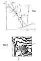
- the measurement of the profile profile can be restricted to a certain direction by suitable alignment of the test surface with respect to the grating arranged in front of the evaluation plane and the interference lines generated by the beams 21 and 22 (FIG. 2), thereby evaluating the generated ones Line fields, for example when checking the unevenness of magnetic storage disks, is greatly facilitated.
- the lattice constant so small that the lattice structure is not visible during observation or evaluation. In this way, the line patterns can be evaluated particularly well without interference from the grid lines.
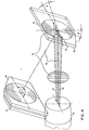
- a coherent light beam 11 is generated by a light source 10 designed as a laser and is expanded in a lens system consisting of lenses 12 and 13.
- the coherent and collimated light beam leaving the lens 13 is split on a prism 16, which has a partially reflecting front surface 14 and a completely reflecting rear surface 15, into two beams 21 and 22, which form an angle 0 with one another.
- These bundles of rays are reflected on an object surface 23 to be tested, for example representing the coated area of a magnetic storage disk, and overlap in the area of an evaluation plane 25.
- a line pattern is formed behind the grating 24, the lines of which represent isoclinics, due to the phase differences occurring during reflection on the unevenness of the object surface 23. These lines thus represent the first derivatives and the distances between them the second derivatives of the object surface 23.
- the evaluation can be carried out either visually or via a television monitor.
- a two-dimensional photodiode array 26 is arranged in the evaluation plane.
- the electrical signals occurring at the outputs of this device contain precise information about the course of the individual lines of the light pattern occurring behind the grating 24 and can be fed to a computer (not shown) for further processing, for example.
- FIG. 3 shows a light pattern consisting of a plurality of lines 6, as occurs, for example, behind the grating 24 of the exemplary embodiment of the invention shown in FIG. 2.
- the distance between adjacent isoclins is small, corresponding to a large local slope of the surface.
- the optical arrangement with the lowest possible sensitivity to small tilting of the measuring surface and evaluation grid is present when the measuring surface is illuminated vertically.
- a partially mirrored beam splitter plate must be introduced into this beam path, which in turn leads to disturbances in the wave field and to an undesired loss of light.
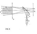
- FIG. 4 shows a parallel arrangement of the measuring surface 45 to the evaluation grid 46, which is insensitive to tilting about axes perpendicular to the interference lines 43.
- the two beam bundles with axes 41 and 42 (lying in a horizontal plane) emerging from the beam expansion optics 40 generate perpendicular interference lines 43 which, with the likewise vertically arranged lines of the grating 46, generate the desired isoclinics on an observation screen 47.
- the common optical axis of the two beams 41 and 42 is identified by reference numeral 44.
- a further prerequisite for realizing the high measurement accuracy of the method described here is an interference-free interference field (43 in FIG. 4), the individual interference lines of which show as few deviations from straight lines as possible. Since such interference fields only arise from beams with plane wave fronts (deviations: 29 2, / 10), the optical components for beam expansion (12 in FIG. 2), for collimation of the beam (13) and for splitting into two beams must be used (prismatic plate 15) the highest demands are made.
- FIG. 5 shows a simple and yet very precise optical system for generating almost interference-free interference line fields in an overlap region 57 (shown by hatching).
- a pinhole 51 is arranged in the focal point of a beam expansion lens 52, the optical axis of which lies at the intersection point C of a double mirror 53a, 53b .
- the mirrors 53a, 53b span an angle of almost 180 ° and can be rotated about their intersection C.
- a collimator 55 is arranged in front of the double mirror in such a way that its optical axis runs through the intersection C and its focal point coincides with pinhole 51.
- the light cone emanating from pinhole 51 is reflected on the mirrors 53a, 53b and thus generates two virtual light sources 54a, 54b, which lie in a common plane E with a very small mutual distance.
- the parallel beams A, B generated by the collimator 55, which emanate from these light sources, form an angle 9 which corresponds to the formula is given, where g represents the lattice constant of the interference field in the overlap region 57.
- the lattice constant of the interference field can be set in a simple manner by changing the angle enclosed by the mirrors 53a, 53b; the direction of the interference line field can be adjusted by rotating the double mirror 53a, 53b about its axis c.
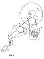
- FIG. 6 shows the structure of a complete arrangement for interferometric flatness measurement with a double mirror according to FIG. 5.
- the output beam of a laser 60 is focused via a deflecting mirror 61 and a converging lens 62 in the opening of a pinhole 63 and split into two beams by double mirrors 64, which enclose a small angle with one another and, for example in region 65, in which a collimator lens is arranged, generate an interference field consisting of horizontally oriented straight lines.
- the surface to be tested here a magnetic disk 66
- the resulting isoclinics are shown schematically at the location of the grid 68.
- the surface of the magnetic plate 66 is checked in the radial direction (the test direction is always perpendicular to the orientation of the interference lines projected onto the measuring surface).
- the flatness test in the tangential direction can be carried out with the same structure if the magnetic plate 66 is shifted downward at an angle of 45 ° (according to arrow 600) until the illumination in area 69 takes place. In this area 69, the interference lines run in the radial direction, so that the flatness test takes place in the tangential direction.
- the entire surface is measured in sections.
- the test in two directions running perpendicular to one another can also be carried out in such a way that the same plate section is illuminated a second time after the double mirror 64 and evaluation grid 68 have been rotated through 90 °.
- Fig. 7 shows schematically the components of a complete system for interferometric flatness measurement of magnetic disks with digital image processing.
- the test specimen 70 is illuminated in the manner shown in FIG. 6 with two beams 71 inclined towards one another and the resulting isoclinics are scanned with a television camera 72.
- a Fresnel lens is used instead of the matt screen arranged behind the grating 68, which causes the isoclines to be imaged on the photosensitive surface of the television camera.
- the output signal of the television camera 72 is fed to a video mixer 74, to which a television monitor 75 is connected, and to an analog-to-digital converter 73, which transfers the digitized image to a digital memory 77 via an interface 76 operating at high speed.
- An image processor connected to the memory 77 processes the digital image and also supplies it to the television monitor 75 via the memory 77, the interface 76 and the video mixer 74. The original and the processed image can thus be displayed on the television monitor 75 at the same time.
- a terminal 79 is connected to the image processor 78; the step-by-step advancement of the individual sections of plate 70 to be checked takes place with a stepper motor 700 with an associated control unit 701.
- the isoclinic pattern can also be scanned with a photodiode matrix.
- the evaluation grid (for example 24; FIG. 2) can be produced with the aid of the measuring device described here in such a way that a perfect flat mirror (for example mercury surface) is used as the measuring surface 23 so that it can be illuminated by the measuring beams 21, 22 to register holographic-photographic interference patterns as a grid.
- a perfect flat mirror for example mercury surface
- the evaluation grating can be registered with suitable photosensitive materials either as an amplitude grating (e.g. black and white modulated) or as a phase grating (change in refractive index). Errors in the measuring device therefore already influence the structure of the evaluation grid and are thus partially compensated for during the later measurement of test objects.
- the flat mirror that was used to record the grating can be attached to the 45 ° ramp (arrow 600 in FIG. 6) so firmly that control measurements can be carried out at any time between the individual measurements. However, as experience shows, no errors can be identified even over months of measurement.
Landscapes
- Physics & Mathematics (AREA)
- General Physics & Mathematics (AREA)
- Length Measuring Devices By Optical Means (AREA)
Claims (8)
Priority Applications (3)
| Application Number | Priority Date | Filing Date | Title |
|---|---|---|---|
| DE8181710020T DE3175207D1 (en) | 1981-05-29 | 1981-05-29 | Process and device for interferometric evenness measurement |
| EP81710020A EP0066030B1 (fr) | 1981-05-29 | 1981-05-29 | Dispositif et procédé pour la mesure interférométrique de planéité |
| JP3825982A JPS57200808A (en) | 1981-05-29 | 1982-03-12 | Method of measuring interfering flatness |
Applications Claiming Priority (1)
| Application Number | Priority Date | Filing Date | Title |
|---|---|---|---|
| EP81710020A EP0066030B1 (fr) | 1981-05-29 | 1981-05-29 | Dispositif et procédé pour la mesure interférométrique de planéité |
Publications (2)
| Publication Number | Publication Date |
|---|---|
| EP0066030A1 EP0066030A1 (fr) | 1982-12-08 |
| EP0066030B1 true EP0066030B1 (fr) | 1986-08-27 |
Family
ID=8188615
Family Applications (1)
| Application Number | Title | Priority Date | Filing Date |
|---|---|---|---|
| EP81710020A Expired EP0066030B1 (fr) | 1981-05-29 | 1981-05-29 | Dispositif et procédé pour la mesure interférométrique de planéité |
Country Status (3)
| Country | Link |
|---|---|
| EP (1) | EP0066030B1 (fr) |
| JP (1) | JPS57200808A (fr) |
| DE (1) | DE3175207D1 (fr) |
Families Citing this family (3)
| Publication number | Priority date | Publication date | Assignee | Title |
|---|---|---|---|---|
| CH693968A5 (de) * | 1993-04-21 | 2004-05-14 | Fraunhofer Ges Forschung | Verfahren und Vorrichtung fuer die Topographiepruefung von Oberflaechen. |
| EP2846129A1 (fr) * | 2013-09-10 | 2015-03-11 | BAE Systems PLC | Mesure optique de rugosité de surface |
| WO2015036732A1 (fr) * | 2013-09-10 | 2015-03-19 | Bae Systems Plc | Mesure d'une rugosité de surface optique |
Citations (8)
| Publication number | Priority date | Publication date | Assignee | Title |
|---|---|---|---|---|
| US3439988A (en) * | 1964-04-27 | 1969-04-22 | Data Products Corp | Apparatus for inspecting a reflective surface which includes a projector of a pattern of lines having different thicknesses |
| DE2100304A1 (de) * | 1970-01-06 | 1971-07-15 | Commissariat Energie Atomique | Verfahren und Vorrichtung zum zer störungsfreien Messen von Oberflachen zuständen |
| DE2139836B2 (de) * | 1971-08-09 | 1975-10-30 | Ibm Deutschland Gmbh, 7000 Stuttgart | Verfahren zum berührungslosen Messen der Unebenheilen von Oberflächen |
| DE2500798A1 (de) * | 1975-01-10 | 1976-07-15 | Leitz Ernst Gmbh | Optisches messystem |
| DE2537162B1 (de) * | 1975-08-21 | 1976-09-23 | Ibm Deutschland Gmbh, 7000 Stuttgart | Verfahren zum beruehrungslosen messen der unebenheiten von oberflaechen |
| DE2636498B1 (de) * | 1976-08-13 | 1977-05-12 | Ibm Deutschland | Verfahren zur interferometrischen oberflaechenmessung |
| DE2636211B1 (de) * | 1976-08-12 | 1977-06-02 | Ibm Deutschland | Interferometrisches verfahren zur abstands- oder ebenheitsmessung |
| DE2622787B1 (de) * | 1976-05-21 | 1977-09-22 | Ibm Deutschland | Verfahren zur interferometrischen abstands-, dicken- oder ebenheitsmessung |
Family Cites Families (4)
| Publication number | Priority date | Publication date | Assignee | Title |
|---|---|---|---|---|
| US3907438A (en) * | 1973-06-22 | 1975-09-23 | Gen Electric | Contour measuring system for cylinders |
| US3943278A (en) * | 1974-08-22 | 1976-03-09 | Stanford Research Institute | Surface deformation gauging system by moire interferometry |
| US4070683A (en) * | 1976-03-04 | 1978-01-24 | Altschuler Bruce R | Optical surface topography mapping system |
| JPS6138401A (ja) * | 1984-07-30 | 1986-02-24 | Shisaka Kenkyusho:Kk | 伸縮あるいは変位の拡大機構 |
-
1981
- 1981-05-29 EP EP81710020A patent/EP0066030B1/fr not_active Expired
- 1981-05-29 DE DE8181710020T patent/DE3175207D1/de not_active Expired
-
1982
- 1982-03-12 JP JP3825982A patent/JPS57200808A/ja active Pending
Patent Citations (8)
| Publication number | Priority date | Publication date | Assignee | Title |
|---|---|---|---|---|
| US3439988A (en) * | 1964-04-27 | 1969-04-22 | Data Products Corp | Apparatus for inspecting a reflective surface which includes a projector of a pattern of lines having different thicknesses |
| DE2100304A1 (de) * | 1970-01-06 | 1971-07-15 | Commissariat Energie Atomique | Verfahren und Vorrichtung zum zer störungsfreien Messen von Oberflachen zuständen |
| DE2139836B2 (de) * | 1971-08-09 | 1975-10-30 | Ibm Deutschland Gmbh, 7000 Stuttgart | Verfahren zum berührungslosen Messen der Unebenheilen von Oberflächen |
| DE2500798A1 (de) * | 1975-01-10 | 1976-07-15 | Leitz Ernst Gmbh | Optisches messystem |
| DE2537162B1 (de) * | 1975-08-21 | 1976-09-23 | Ibm Deutschland Gmbh, 7000 Stuttgart | Verfahren zum beruehrungslosen messen der unebenheiten von oberflaechen |
| DE2622787B1 (de) * | 1976-05-21 | 1977-09-22 | Ibm Deutschland | Verfahren zur interferometrischen abstands-, dicken- oder ebenheitsmessung |
| DE2636211B1 (de) * | 1976-08-12 | 1977-06-02 | Ibm Deutschland | Interferometrisches verfahren zur abstands- oder ebenheitsmessung |
| DE2636498B1 (de) * | 1976-08-13 | 1977-05-12 | Ibm Deutschland | Verfahren zur interferometrischen oberflaechenmessung |
Also Published As
| Publication number | Publication date |
|---|---|
| EP0066030A1 (fr) | 1982-12-08 |
| DE3175207D1 (en) | 1986-10-02 |
| JPS57200808A (en) | 1982-12-09 |
Similar Documents
| Publication | Publication Date | Title |
|---|---|---|
| DE19624421B4 (de) | Vorrichtung und Verfahren zur ortsaufgelösten Vermessung von Wellenfrontdeformationen | |
| EP0419936B1 (fr) | Procédé et dispositif pour la détection de phase de rayonnement notamment de rayonnement lumineux | |
| DE69722876T2 (de) | Vorrichtung und Verfahren zur optischen Profilmessung | |
| DE69225858T2 (de) | Verfahren und Vorrichtung zur Messung von Lageabweichungen von mehreren auf einem Objekt aufgebrachten Beugungsgittern | |
| DE1548707A1 (de) | Fotoelektrischer Schrittgeber | |
| DE2620091A1 (de) | Messystem zum bestimmen der kontur der oberflaeche eines gegenstands | |
| DE4235832B4 (de) | Vorrichtung und Verfahren zum Überprüfen eines Dachwinkels eines optischen Elements | |
| DE69705927T2 (de) | Teilchenmessgerät und Methode zu seiner Kalibrierung | |
| EP0210263B1 (fr) | Dispositifs pour la determination optique d'erreurs de forme de faible importance | |
| DE102009012508B3 (de) | Autokollimationsfernrohr mit Kamera | |
| DE69526321T2 (de) | Verfahren zum Bestimmen der Position einer optischen Faser | |
| DE69314829T2 (de) | Krümmungsmessung einer Oberfläche | |
| EP0066030B1 (fr) | Dispositif et procédé pour la mesure interférométrique de planéité | |
| EP0040700B1 (fr) | Procédé et arrangement pour tester des systèmes optiques | |
| DE4036120A1 (de) | Verfahren und vorrichtung zur bestimmung der wegaenderung von strahlen, vorzugsweise lichtstrahlen | |
| DE3789901T2 (de) | Entfernungsmessung mit hilfe von diffraktion. | |
| DE1797240B2 (de) | Vorrichtung zum holographischen speichern | |
| EP3571465B1 (fr) | Dispositif et procédé d'étalonnage d'un appareil de mesure au moyen de motifs projetés | |
| DE19856400B4 (de) | Verfahren und Vorrichtung zur direkten Phasenmessung von Strahlung | |
| DE2622787C2 (de) | Verfahren zur interferometrischen Abstands-, Dicken- oder Ebenheitsmessung | |
| DE69319542T2 (de) | Apparat zum Messen der Verteilung eines elektromagnetischen Feldes mit einem fokussierten Elektronenstrahl | |
| DE19545367C2 (de) | Vorrichtung und Verfahren zur optischen Profilmessung, insbesondere an gekrümmten Objektoberflächen | |
| DD224401A1 (de) | Einrichtung zur bestimmung geometrischer abmessungen an messobjekten | |
| DD249759A1 (de) | Verfahren zur strahlendichtemessung lichtemittierender quellen in echtzeit | |
| DE4329626A1 (de) | Längen- oder Winkelmeßeinrichtung |
Legal Events
| Date | Code | Title | Description |
|---|---|---|---|
| PUAI | Public reference made under article 153(3) epc to a published international application that has entered the european phase |
Free format text: ORIGINAL CODE: 0009012 |
|
| 17P | Request for examination filed |
Effective date: 19820713 |
|
| AK | Designated contracting states |
Designated state(s): DE FR GB |
|
| GRAA | (expected) grant |
Free format text: ORIGINAL CODE: 0009210 |
|
| AK | Designated contracting states |
Kind code of ref document: B1 Designated state(s): DE FR GB |
|
| REF | Corresponds to: |
Ref document number: 3175207 Country of ref document: DE Date of ref document: 19861002 |
|
| ET | Fr: translation filed | ||
| R20 | Corrections of a patent specification |
Effective date: 19860925 |
|
| PLBE | No opposition filed within time limit |
Free format text: ORIGINAL CODE: 0009261 |
|
| STAA | Information on the status of an ep patent application or granted ep patent |
Free format text: STATUS: NO OPPOSITION FILED WITHIN TIME LIMIT |
|
| 26N | No opposition filed | ||
| GBPC | Gb: european patent ceased through non-payment of renewal fee | ||
| PG25 | Lapsed in a contracting state [announced via postgrant information from national office to epo] |
Ref country code: GB Free format text: LAPSE BECAUSE OF NON-PAYMENT OF DUE FEES Effective date: 19881121 |
|
| PGFP | Annual fee paid to national office [announced via postgrant information from national office to epo] |
Ref country code: FR Payment date: 19890426 Year of fee payment: 9 |
|
| PG25 | Lapsed in a contracting state [announced via postgrant information from national office to epo] |
Ref country code: FR Effective date: 19910131 |
|
| REG | Reference to a national code |
Ref country code: FR Ref legal event code: ST |
|
| PGFP | Annual fee paid to national office [announced via postgrant information from national office to epo] |
Ref country code: DE Payment date: 19910525 Year of fee payment: 11 |
|
| PG25 | Lapsed in a contracting state [announced via postgrant information from national office to epo] |
Ref country code: DE Effective date: 19930202 |