EP0066638A1 - Interrupteur pour l'achèvement du déplacement d'un vilebrequin en centrage d'équilibrage - Google Patents
Interrupteur pour l'achèvement du déplacement d'un vilebrequin en centrage d'équilibrage Download PDFInfo
- Publication number
- EP0066638A1 EP0066638A1 EP81104386A EP81104386A EP0066638A1 EP 0066638 A1 EP0066638 A1 EP 0066638A1 EP 81104386 A EP81104386 A EP 81104386A EP 81104386 A EP81104386 A EP 81104386A EP 0066638 A1 EP0066638 A1 EP 0066638A1
- Authority
- EP
- European Patent Office
- Prior art keywords
- crankshaft
- axis
- balance
- light
- centering
- Prior art date
- Legal status (The legal status is an assumption and is not a legal conclusion. Google has not performed a legal analysis and makes no representation as to the accuracy of the status listed.)
- Granted
Links
- 238000006073 displacement reaction Methods 0.000 abstract 2
- 238000005259 measurement Methods 0.000 abstract 1
- 238000000034 method Methods 0.000 description 4
- 238000012544 monitoring process Methods 0.000 description 2
- 230000008030 elimination Effects 0.000 description 1
- 238000003379 elimination reaction Methods 0.000 description 1
- 238000003754 machining Methods 0.000 description 1
- 230000003068 static effect Effects 0.000 description 1
Images

Classifications
-
- G—PHYSICS
- G01—MEASURING; TESTING
- G01M—TESTING STATIC OR DYNAMIC BALANCE OF MACHINES OR STRUCTURES; TESTING OF STRUCTURES OR APPARATUS, NOT OTHERWISE PROVIDED FOR
- G01M1/00—Testing static or dynamic balance of machines or structures
- G01M1/02—Details of balancing machines or devices
-
- G—PHYSICS
- G01—MEASURING; TESTING
- G01M—TESTING STATIC OR DYNAMIC BALANCE OF MACHINES OR STRUCTURES; TESTING OF STRUCTURES OR APPARATUS, NOT OTHERWISE PROVIDED FOR
- G01M1/00—Testing static or dynamic balance of machines or structures
- G01M1/14—Determining imbalance
- G01M1/16—Determining imbalance by oscillating or rotating the body to be tested
- G01M1/24—Performing balancing on elastic shafts, e.g. for crankshafts
Definitions
- the invention relates to a switch for ending an adjustment of a crankshaft when balancing in a balancing centering machine, the balancing centering machine having a bearing bed and a spring bridge supported on it by springs, in which the crankshaft to be balanced is rotated about the balancing centering machine axis, and the crankshaft axis to the balancing centering machine axis up to one minimal rotation radius of a point on the surface of two selected crankshaft sections rotating without system-related eccentricities about the balancing machine axis.
- the other devices and methods for centering the elongation of elongated bodies, such as crankshafts, mentioned in the said publication do not contain any device for measuring and monitoring the minimum rotation radius.
- the present invention is based on the object of clearly avoiding large geometric eccentricities which occur during centering and which cause rejects in the finishing of a crankshaft around the center of the shaft shaft.
- This object is achieved in that two transmitters for sharply focused light are arranged on the oscillating bridge, send the light beams opposite receivers, which are also arranged on the oscillating bridge, and that the light beams cross the balancing machine axis at a distance of the minimum radius, and in that the adjustment is interrupted when a receiver receives light for the first time via a crankshaft section.
- the switch according to the invention thus enables the instantaneous position of the crankshaft to be balanced to be used as a switch-off pulse, and also when the monitored distance of the crankshaft is shaded by additional units during rotation. A reject in the subsequent mechanical machining of the crankshaft, caused by a large geometric eccentricity, is thus avoided.
- One embodiment of the invention consists in that at least one further transmitting and receiving arrangement for sharply focused light is provided for detecting the curvature of the crankshaft.
- This inventive configuration makes it possible that even "crooked" crankshafts can be centered on the weight, and thus can be further processed, since by monitoring the already crooked crankshaft and when setting large geometric eccentricities, the curvature is also monitored by this additional light switch, and this also immediately shuts off the adjustment process if, with sufficient material quantity at the other points on the crankshaft, a light beam reaches the corresponding receiver due to the curvature of the crankshaft.
- the light beams cross the balancing machine axis at an oblique angle. This configuration allows flexibility in the cultivation and at the same time achieves the elimination of any shading agents.
- a transmitter 3 and a receiver 4 are arranged on a swing frame 1, 2.
- the sharply focused light can be a laser beam, which is received in a photo element designed as a receiver, and which is imbalanced when a light pulse is received via a threshold switch 5
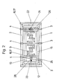
- Measuring device 6 of the balancing machine engages in such a way that the switches 7, 8 which cause the adjustment of a crankshaft 9, the stepping motors 10, 1.1 are stopped immediately, and the crank shaft 9 is locked in this position, on its shaft end faces by drills 23, 24 acting in the balancing machine axis 22 , is centered (see Figure 2).
- the crankshaft is stored in a so-called cage 12 (see FIG. 2).
- the cage 12 is provided with longitudinal spars 13, 14 and 15, which extend over the entire length of the crankshaft 9 to be examined.
- the motors 10 and 11 and counterholders 16, 17 are arranged on this cage.
- a pair of motors 10 and 11 and a pair of counterholders 16, 17 are provided for each of the adjustment planes 25, 26 in order to be able to spatially adjust the entire length of the crankshaft as it rotates in accordance with the measured static and dynamic imbalances until it is observed of the switch according to the invention, the unbalance is switched off in the prescribed manner.
- the end journal 28 of the crankshaft 9 is scanned by an obliquely running transceiver system.
Landscapes
- Physics & Mathematics (AREA)
- General Physics & Mathematics (AREA)
- Testing Of Balance (AREA)
Priority Applications (8)
| Application Number | Priority Date | Filing Date | Title |
|---|---|---|---|
| AT81104386T ATE14795T1 (de) | 1981-06-06 | 1981-06-06 | Schalter zur beendigung der verstellung einer kurbelwelle beim wuchtzentrieren. |
| EP81104386A EP0066638B1 (fr) | 1981-06-06 | 1981-06-06 | Interrupteur pour l'achèvement du déplacement d'un vilebrequin en centrage d'équilibrage |
| DE8181104386T DE3171691D1 (en) | 1981-06-06 | 1981-06-06 | Switch for ending the adjustment of a crankshaft at balance centering |
| AR289182A AR231334A1 (es) | 1981-06-06 | 1982-04-22 | Dispositivo para terminar el desplazamiento de un ciguenal en el centrado por equilibrio de una maquina de centrado por equilibrio |
| BR8202636A BR8202636A (pt) | 1981-06-06 | 1982-05-07 | Chave destinada a terminar com os deslocamentos de um virabrequim durante a centragem de suas massas centrifugas |
| ES512648A ES8305130A1 (es) | 1981-06-06 | 1982-05-28 | "perfeccionamientos en interruptores para terminar el ajuste de un ciguenal al centrar en cuanto a masas de inercia". |
| US06/384,191 US4446732A (en) | 1981-06-06 | 1982-06-03 | Crankshaft balance centering |
| MX193011A MX152317A (es) | 1981-06-06 | 1982-06-04 | Mejoras en interruptor para determinar el ajuste de un ciguenal durante el centrado del equilibrio en una maquina centradora |
Applications Claiming Priority (1)
| Application Number | Priority Date | Filing Date | Title |
|---|---|---|---|
| EP81104386A EP0066638B1 (fr) | 1981-06-06 | 1981-06-06 | Interrupteur pour l'achèvement du déplacement d'un vilebrequin en centrage d'équilibrage |
Publications (2)
| Publication Number | Publication Date |
|---|---|
| EP0066638A1 true EP0066638A1 (fr) | 1982-12-15 |
| EP0066638B1 EP0066638B1 (fr) | 1985-08-07 |
Family
ID=8187758
Family Applications (1)
| Application Number | Title | Priority Date | Filing Date |
|---|---|---|---|
| EP81104386A Expired EP0066638B1 (fr) | 1981-06-06 | 1981-06-06 | Interrupteur pour l'achèvement du déplacement d'un vilebrequin en centrage d'équilibrage |
Country Status (8)
| Country | Link |
|---|---|
| US (1) | US4446732A (fr) |
| EP (1) | EP0066638B1 (fr) |
| AR (1) | AR231334A1 (fr) |
| AT (1) | ATE14795T1 (fr) |
| BR (1) | BR8202636A (fr) |
| DE (1) | DE3171691D1 (fr) |
| ES (1) | ES8305130A1 (fr) |
| MX (1) | MX152317A (fr) |
Cited By (2)
| Publication number | Priority date | Publication date | Assignee | Title |
|---|---|---|---|---|
| DE3843318A1 (de) * | 1988-12-22 | 1990-06-28 | Hofmann Gmbh & Co Kg Maschinen | Verfahren und vorrichtung zur messung von lageungenauigkeiten von an einem auszuwuchtenden rotor in verschiedenen winkellagen vorhandenen kreiszylindrischen lagerstellen |
| EP0514726A1 (fr) * | 1991-05-24 | 1992-11-25 | Carl Schenck Ag | Méthode pour considérer, pendant l'équilibrage, la déviation de position des manetons de la bielle d'un vilebrequin et dispositif pour cela |
Families Citing this family (9)
| Publication number | Priority date | Publication date | Assignee | Title |
|---|---|---|---|---|
| EP0268724B1 (fr) * | 1986-11-26 | 1989-03-15 | GFM Gesellschaft für Fertigungstechnik und Maschinenbau Gesellschaft m.b.H. | Méthode et machine à centrer équilibrée pour des pièces partiellement usinées, spécialement des vilebrequins |
| US4974449A (en) * | 1988-08-23 | 1990-12-04 | Steve Core | Method for balancing the crankshaft in an uneven degree firing engine |
| US6303896B1 (en) * | 1999-08-02 | 2001-10-16 | Visteon Global Technologies, Inc. | Dynamic laser balancing |
| WO2004058931A1 (fr) | 2002-12-20 | 2004-07-15 | Henkel Kommanditgesellschaft Auf Aktien | Produits de lavage et de nettoyage contenant un agent de blanchiment |
| US7197837B1 (en) | 2005-03-15 | 2007-04-03 | Honda Motor Co., Ltd. | Gauge assembly for measuring diameter and total indicated runout |
| DE102012102499B4 (de) * | 2012-03-23 | 2018-10-11 | Mag Ias Gmbh | Verfahren zur Endenbearbeitung sowie hierfür geeignete Maschine |
| US10047824B2 (en) * | 2014-07-29 | 2018-08-14 | Deere & Company | Method for pre-balancing and machining a crankshaft based on a mass distribution method |
| US10302520B2 (en) * | 2016-11-01 | 2019-05-28 | Dominion Technologies Group, Inc. | Crankshaft balancer suspension assembly |
| US10821527B2 (en) | 2018-10-03 | 2020-11-03 | GM Global Technology Operations LLC | Method of manufacturing a crankshaft |
Citations (2)
| Publication number | Priority date | Publication date | Assignee | Title |
|---|---|---|---|---|
| US4141130A (en) * | 1977-12-05 | 1979-02-27 | H. C. Price Co. | Method and apparatus for centering two concentric cylinders |
| DE2823219A1 (de) * | 1978-05-27 | 1979-11-29 | Schenck Ag Carl | Verfahren und vorrichtung zum zentrieren von mit ungleicher massenverteilung laengs ihrer schaftachse versehenen rotationskoerpern |
Family Cites Families (3)
| Publication number | Priority date | Publication date | Assignee | Title |
|---|---|---|---|---|
| US2746299A (en) * | 1951-06-11 | 1956-05-22 | Carll Schenck Maschinenfabrik | Apparatus for the balance centering of revolvable bodies |
| FR1209840A (fr) * | 1956-08-23 | 1960-03-03 | Schenck Gmbh Carl | Procédé et dispositif d'usinage des pièces tournantes, en particulier pour le centrage dynamique |
| US3952602A (en) * | 1971-03-03 | 1976-04-27 | Cambridge Thermionic Corporation | Rotor balancing apparatus and system |
-
1981
- 1981-06-06 EP EP81104386A patent/EP0066638B1/fr not_active Expired
- 1981-06-06 AT AT81104386T patent/ATE14795T1/de active
- 1981-06-06 DE DE8181104386T patent/DE3171691D1/de not_active Expired
-
1982
- 1982-04-22 AR AR289182A patent/AR231334A1/es active
- 1982-05-07 BR BR8202636A patent/BR8202636A/pt not_active IP Right Cessation
- 1982-05-28 ES ES512648A patent/ES8305130A1/es not_active Expired
- 1982-06-03 US US06/384,191 patent/US4446732A/en not_active Expired - Lifetime
- 1982-06-04 MX MX193011A patent/MX152317A/es unknown
Patent Citations (2)
| Publication number | Priority date | Publication date | Assignee | Title |
|---|---|---|---|---|
| US4141130A (en) * | 1977-12-05 | 1979-02-27 | H. C. Price Co. | Method and apparatus for centering two concentric cylinders |
| DE2823219A1 (de) * | 1978-05-27 | 1979-11-29 | Schenck Ag Carl | Verfahren und vorrichtung zum zentrieren von mit ungleicher massenverteilung laengs ihrer schaftachse versehenen rotationskoerpern |
Cited By (3)
| Publication number | Priority date | Publication date | Assignee | Title |
|---|---|---|---|---|
| DE3843318A1 (de) * | 1988-12-22 | 1990-06-28 | Hofmann Gmbh & Co Kg Maschinen | Verfahren und vorrichtung zur messung von lageungenauigkeiten von an einem auszuwuchtenden rotor in verschiedenen winkellagen vorhandenen kreiszylindrischen lagerstellen |
| EP0514726A1 (fr) * | 1991-05-24 | 1992-11-25 | Carl Schenck Ag | Méthode pour considérer, pendant l'équilibrage, la déviation de position des manetons de la bielle d'un vilebrequin et dispositif pour cela |
| DE4117051A1 (de) * | 1991-05-24 | 1992-11-26 | Schenck Ag Carl | Verfahren zur beruecksichtigung von lageabweichungen der kurbelzapfen einer kurbelwelle beim auswuchten und vorrichtung hierzu |
Also Published As
| Publication number | Publication date |
|---|---|
| ES512648A0 (es) | 1983-04-16 |
| DE3171691D1 (en) | 1985-09-12 |
| MX152317A (es) | 1985-06-26 |
| ATE14795T1 (de) | 1985-08-15 |
| EP0066638B1 (fr) | 1985-08-07 |
| AR231334A1 (es) | 1984-10-31 |
| ES8305130A1 (es) | 1983-04-16 |
| US4446732A (en) | 1984-05-08 |
| BR8202636A (pt) | 1983-04-19 |
Similar Documents
| Publication | Publication Date | Title |
|---|---|---|
| EP0066638B1 (fr) | Interrupteur pour l'achèvement du déplacement d'un vilebrequin en centrage d'équilibrage | |
| DE2823219C2 (de) | Verfahren und Vorrichtung zum Zentrieren von mit ungleicher Massenverteilung längs ihrer Schaftachse versehenen Rotationskörpern | |
| DE4038121C2 (fr) | ||
| DE4444992A1 (de) | Vorrichtung zum Unwuchtausgleich von Rotationskörpern, insbesondere von Schleifscheiben | |
| DE2238310A1 (de) | Maschine zum polieren und klaeren | |
| DE4024258C2 (de) | Verfahren und Vorrichtung zum Herstellen des dynamischen Gleichgewichtes eines Rotationskörpers | |
| DE3727487C2 (fr) | ||
| DE69518619T2 (de) | Auswuchtungsvorrichtung für einen Abtastmotor | |
| EP0136716B1 (fr) | Machine-outil pour le traitement des surfaces | |
| DE3002682A1 (de) | Verfahren und vorrichtung zur massenungleichfoermigkeitsmessung an einem rotor, insbesondere kreisel | |
| DE10054689C1 (de) | Verfahren zur Beseitigung einer Unwucht eines rotierenden Werkstückes | |
| DE1785232A1 (de) | Lagervorrichtung fuer Spinn- oder Zwirnspindel | |
| CH415335A (de) | Kurbelwellenschleifmaschine | |
| DE4117051C2 (fr) | ||
| EP1195457B1 (fr) | Aiguisage des éléments de travail d'une machine de cardage | |
| DE590759C (de) | Verfahren und Einrichtung zur Zentrierung von umlaufenden Teilen, insbesondere von Kurbelwellen o. dgl. | |
| DE913364C (de) | Verfahren und Einrichtung zum Auswuchten von vorbearbeiteten Rotationskoerpern durch Verlagern ihrer Haupttraegheitsachse | |
| DE2822342B2 (de) | Maschine zum Bearbeiten von Werkstücken mit sphärischer Oberfläche mit magnetisierbarem, zwischen zwei Magneten gehaltenem Schleifpulver | |
| DE19743577A1 (de) | Verfahren und Einrichtung zum Vorbereiten eines Wuchtapparates auf einen Wuchtvorgang | |
| DE2644475A1 (de) | Verfahren und vorrichtung zum massenausgleich an rotierenden maschinen | |
| DE3715479C2 (de) | Verfahren und Einrichtung zur Aufrechterhaltung einer konstanten Haltekraft auf eine Scheibe in einer Rotationsstation | |
| DE1202533B (de) | Einrichtung zum Wuchtzentrieren von Umlaufkoerpern | |
| EP0618318A1 (fr) | Appareil pour attacher des éléments de travail | |
| DE2927467A1 (de) | Hilfsvorrichtung fuer die bearbeitung zweipoliger laeufer auf einer drehbank | |
| DE19912921B4 (de) | Meßvorrichtung zur Qualitätsprüfung von Zahnrädern und Zahnwellen |
Legal Events
| Date | Code | Title | Description |
|---|---|---|---|
| PUAI | Public reference made under article 153(3) epc to a published international application that has entered the european phase |
Free format text: ORIGINAL CODE: 0009012 |
|
| 17P | Request for examination filed |
Effective date: 19820503 |
|
| AK | Designated contracting states |
Designated state(s): AT DE FR GB IT SE |
|
| RBV | Designated contracting states (corrected) |
Designated state(s): AT DE FR GB IT SE |
|
| ITF | It: translation for a ep patent filed | ||
| GRAA | (expected) grant |
Free format text: ORIGINAL CODE: 0009210 |
|
| AK | Designated contracting states |
Designated state(s): AT DE FR GB IT SE |
|
| REF | Corresponds to: |
Ref document number: 14795 Country of ref document: AT Date of ref document: 19850815 Kind code of ref document: T |
|
| REF | Corresponds to: |
Ref document number: 3171691 Country of ref document: DE Date of ref document: 19850912 |
|
| ET | Fr: translation filed | ||
| PLBE | No opposition filed within time limit |
Free format text: ORIGINAL CODE: 0009261 |
|
| STAA | Information on the status of an ep patent application or granted ep patent |
Free format text: STATUS: NO OPPOSITION FILED WITHIN TIME LIMIT |
|
| 26N | No opposition filed | ||
| PGFP | Annual fee paid to national office [announced via postgrant information from national office to epo] |
Ref country code: AT Payment date: 19930513 Year of fee payment: 13 |
|
| ITTA | It: last paid annual fee | ||
| PGFP | Annual fee paid to national office [announced via postgrant information from national office to epo] |
Ref country code: FR Payment date: 19940511 Year of fee payment: 14 |
|
| PGFP | Annual fee paid to national office [announced via postgrant information from national office to epo] |
Ref country code: SE Payment date: 19940517 Year of fee payment: 14 |
|
| PG25 | Lapsed in a contracting state [announced via postgrant information from national office to epo] |
Ref country code: AT Effective date: 19940606 |
|
| EAL | Se: european patent in force in sweden |
Ref document number: 81104386.8 |
|
| PG25 | Lapsed in a contracting state [announced via postgrant information from national office to epo] |
Ref country code: SE Effective date: 19950607 |
|
| PG25 | Lapsed in a contracting state [announced via postgrant information from national office to epo] |
Ref country code: FR Effective date: 19960229 |
|
| EUG | Se: european patent has lapsed |
Ref document number: 81104386.8 |
|
| REG | Reference to a national code |
Ref country code: FR Ref legal event code: ST |
|
| PGFP | Annual fee paid to national office [announced via postgrant information from national office to epo] |
Ref country code: GB Payment date: 19990517 Year of fee payment: 19 |
|
| PGFP | Annual fee paid to national office [announced via postgrant information from national office to epo] |
Ref country code: DE Payment date: 19990611 Year of fee payment: 19 |
|
| PG25 | Lapsed in a contracting state [announced via postgrant information from national office to epo] |
Ref country code: GB Free format text: LAPSE BECAUSE OF NON-PAYMENT OF DUE FEES Effective date: 20000606 |
|
| GBPC | Gb: european patent ceased through non-payment of renewal fee |
Effective date: 20000606 |
|
| PG25 | Lapsed in a contracting state [announced via postgrant information from national office to epo] |
Ref country code: DE Free format text: LAPSE BECAUSE OF NON-PAYMENT OF DUE FEES Effective date: 20010403 |