EP0066732A2 - Dispositif à élargir et à border des tubes - Google Patents
Dispositif à élargir et à border des tubes Download PDFInfo
- Publication number
- EP0066732A2 EP0066732A2 EP82104272A EP82104272A EP0066732A2 EP 0066732 A2 EP0066732 A2 EP 0066732A2 EP 82104272 A EP82104272 A EP 82104272A EP 82104272 A EP82104272 A EP 82104272A EP 0066732 A2 EP0066732 A2 EP 0066732A2
- Authority
- EP
- European Patent Office
- Prior art keywords
- tool
- flanging
- expansion
- tube
- halves
- Prior art date
- Legal status (The legal status is an assumption and is not a legal conclusion. Google has not performed a legal analysis and makes no representation as to the accuracy of the status listed.)
- Withdrawn
Links
Images

Classifications
-
- B—PERFORMING OPERATIONS; TRANSPORTING
- B21—MECHANICAL METAL-WORKING WITHOUT ESSENTIALLY REMOVING MATERIAL; PUNCHING METAL
- B21D—WORKING OR PROCESSING OF SHEET METAL OR METAL TUBES, RODS OR PROFILES WITHOUT ESSENTIALLY REMOVING MATERIAL; PUNCHING METAL
- B21D39/00—Application of procedures in order to connect objects or parts, e.g. coating with sheet metal otherwise than by plating; Tube expanders
- B21D39/08—Tube expanders
- B21D39/12—Tube expanders with rollers for expanding and flanging
-
- B—PERFORMING OPERATIONS; TRANSPORTING
- B21—MECHANICAL METAL-WORKING WITHOUT ESSENTIALLY REMOVING MATERIAL; PUNCHING METAL
- B21D—WORKING OR PROCESSING OF SHEET METAL OR METAL TUBES, RODS OR PROFILES WITHOUT ESSENTIALLY REMOVING MATERIAL; PUNCHING METAL
- B21D19/00—Flanging or other edge treatment, e.g. of tubes
- B21D19/02—Flanging or other edge treatment, e.g. of tubes by continuously-acting tools moving along the edge
- B21D19/04—Flanging or other edge treatment, e.g. of tubes by continuously-acting tools moving along the edge shaped as rollers
- B21D19/046—Flanging or other edge treatment, e.g. of tubes by continuously-acting tools moving along the edge shaped as rollers for flanging edges of tubular products
Definitions
- the invention relates to an expansion and flanging device according to the preamble of claim 1.
- the expansion and flaring of pipes is e.g. to install pipes in condensers.
- a device or method is e.g. in the article "Process for pulling pipes” in Industrie-excellentr Essen No. 12, pages 160-162, from February 8, 1957.
- a pipe end is clamped into a borehole in a plate by pressing a mandrel into the pipe opening, which widens the pipe and flanges it.
- the mandrel causes cold deformation of the pipe in the borehole.
- the mandrel can either have a smooth surface or be provided with rollers or rollers on the circumference.
- Pipes shaped in this way and fastened to walls remain firmly in the wall and cannot be removed without force.
- the expansion takes place by means of rollers which are arranged parallel to the mandrel axis.
- This type of arrangement means that the rollers are relatively heavily loaded and therefore have a relatively short life.
- the pipes shaped in this way can, however, be used for the rapid connection or assembly of pipelines by inserting a sleeve into the expanded parts of the two pipes and then pressing the two pipe flanges together or otherwise sealing them against one another.
- the object of the invention is therefore to provide an expansion and flanging device which ensures high accuracy and simple operation and is also inexpensive. Furthermore, the device should be convertible for different pipe diameters by a simple handle. In addition, the device is intended for the use of a hand drill as a power source.
- a number of commercially available hand drills can be used as the drive source.
- the clamping device 1 consists of two bodies 4, 5 each provided with slots 3, of which the second body 5 can be pivoted back and forth about a lower axis 6 against and away from the first body 4, so that an unprocessed tube 7 can be used and a machined tube 8 is removable.
- the bodies 4, 5 are firmly connected to one another by means of a screw closure 9.
- This screw closure 9 comprises a link 10 with a square cross-section, which can be pivoted about an axis 11 in the second body 5 and inserted into the slot 3 in the first body 4 and can be manually clamped there by means of a screw 12.
- the operator takes an unprocessed tube 7, e.g. with the left hand, and holds it between the two halves 13 of a jaw in the correct position. He pushes the tube 7 against the bracket 18, which serves as a stop. With his right hand, he then places the link 10 in the slot 3 by means of the screw 12 and tightens the screw 12. So that the tube 7 is ready for processing. Then he actuates the drive for the tool holder or the hand drill and at the same time he moves the tool 13 or the entire hand drill along a guide 14 into the tube 7.
- the jaws 17 are provided on the inside with a thread 19 which is opposite to the direction of rotation of the tool 13.
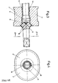
- the tool 13 consists of a mandrel, the outside diameter of which corresponds to the pipe diameter and the finished pipe 8.
- the tube 7 expands to the desired diameter.
- no rolls or rollers are required for the expansion (FIG. 3).
- 15 rollers 16 are used for the flanging. In the case shown, two rollers 16 are provided, but only one or more than two can be used.
- the rollers 16 can be rotatably or fixedly arranged in the mandrel 13.
- roller-like elevations on the surface of the mandrel 13 are recommended. It is also possible to use rotatable rollers arranged in a recessed manner in the peripheral surface of the mandrel 13 for larger pipe diameters.
- FIG. 4 is a schematic view of a clamping jaw is shown, which consists of two halves 17 of which the outer circumference in each case extend over 180 0 and 220, respectively, for example - is 240 °.
- the center of the mandrel is eccentric with respect to the center of these two jaw halves 17. This prevents the halves from twisting during the expanding and flanging process or from falling out when the clamping device is opened.
- the insertion and replacement of the jaw halves 17 can be accomplished simply by inserting and rotating them from the tool side until e.g. a not shown projection on the outer surface of the two jaw halves 17 engages in a correspondingly designed lock in the bodies 4 and 5.
- the insertion and replacement of the jaw halves 17, which are provided with a bayonet lock, can thus be carried out simply and quickly.
- the inside diameter of the jaw halves 17 and the outside diameter of the tool 13 must of course correspond to the diameter of the pipe 7 to be machined.
- the device shown is easy and quick to use and ensures perfect expansion and flaring of pipes, e.g. made of copper or steel.
Landscapes
- Engineering & Computer Science (AREA)
- Mechanical Engineering (AREA)
- Earth Drilling (AREA)
- Shaping Of Tube Ends By Bending Or Straightening (AREA)
Applications Claiming Priority (2)
| Application Number | Priority Date | Filing Date | Title |
|---|---|---|---|
| CH3708/81A CH650706A5 (de) | 1981-06-05 | 1981-06-05 | Ausweitungs- und boerdelgeraet fuer rohre. |
| CH3708/81 | 1981-06-05 |
Publications (2)
| Publication Number | Publication Date |
|---|---|
| EP0066732A2 true EP0066732A2 (fr) | 1982-12-15 |
| EP0066732A3 EP0066732A3 (fr) | 1983-07-20 |
Family
ID=4261805
Family Applications (1)
| Application Number | Title | Priority Date | Filing Date |
|---|---|---|---|
| EP82104272A Withdrawn EP0066732A3 (fr) | 1981-06-05 | 1982-05-15 | Dispositif à élargir et à border des tubes |
Country Status (3)
| Country | Link |
|---|---|
| EP (1) | EP0066732A3 (fr) |
| CH (1) | CH650706A5 (fr) |
| ZA (1) | ZA823542B (fr) |
Cited By (2)
| Publication number | Priority date | Publication date | Assignee | Title |
|---|---|---|---|---|
| DE3832059A1 (de) * | 1988-09-21 | 1990-03-29 | Howaldtswerke Deutsche Werft | Tauchtiefengesteuerte ausblasventil-einrichtung |
| CN110465599A (zh) * | 2019-08-30 | 2019-11-19 | 上海德朗汽车散热器制造有限公司 | 一种用于汽车全铝中冷器水管的扩口设备 |
Families Citing this family (1)
| Publication number | Priority date | Publication date | Assignee | Title |
|---|---|---|---|---|
| DE3939016A1 (de) * | 1989-11-25 | 1991-05-29 | Xaver Lipp | Vorrichtung zum formen eines flansches oder dergleichen, insbesondere am ende eines duennwandigen metallrohres |
Family Cites Families (4)
| Publication number | Priority date | Publication date | Assignee | Title |
|---|---|---|---|---|
| DE632985C (de) * | 1933-05-13 | 1936-07-17 | Georges Ernest Wagner | Rohrwalze mit Einwalz- und Boerdelrollen und einem Grenzring zur Begrenzung ihres axialen Vorschubes |
| FR976499A (fr) * | 1948-12-15 | 1951-03-19 | Machine à faire les collets et emboîtements sur tuyauterie | |
| DE1552050A1 (de) * | 1965-03-03 | 1970-09-24 | Cyril Pernet | Vorrichtung fuer das Formen von Muffen an den Enden von Rohren aus Weichmetallen |
| FR2389429B1 (fr) * | 1977-05-02 | 1982-02-19 | Electricite De France |
-
1981
- 1981-06-05 CH CH3708/81A patent/CH650706A5/de not_active IP Right Cessation
-
1982
- 1982-05-15 EP EP82104272A patent/EP0066732A3/fr not_active Withdrawn
- 1982-05-21 ZA ZA823542A patent/ZA823542B/xx unknown
Cited By (2)
| Publication number | Priority date | Publication date | Assignee | Title |
|---|---|---|---|---|
| DE3832059A1 (de) * | 1988-09-21 | 1990-03-29 | Howaldtswerke Deutsche Werft | Tauchtiefengesteuerte ausblasventil-einrichtung |
| CN110465599A (zh) * | 2019-08-30 | 2019-11-19 | 上海德朗汽车散热器制造有限公司 | 一种用于汽车全铝中冷器水管的扩口设备 |
Also Published As
| Publication number | Publication date |
|---|---|
| EP0066732A3 (fr) | 1983-07-20 |
| ZA823542B (en) | 1983-04-27 |
| CH650706A5 (de) | 1985-08-15 |
Similar Documents
| Publication | Publication Date | Title |
|---|---|---|
| DE2902919A1 (de) | Verfahren und vorrichtung zum aufspannen von werkzeugen, werkstuecken u.dgl. auf eine drehbare spindel | |
| EP0150414A1 (fr) | Dispositif pour l'ébavurage intérieur de tubes ou de profilés soudés longitudinalement | |
| DE60218339T2 (de) | Rohrbiegemaschine und links- und/oder rechtsbiegevorrichtung | |
| DE4238700C2 (de) | Vorrichtung zur Befestigung von Verbindungselementen an Rohrleitungen | |
| DE2931057A1 (de) | Rohrverformer | |
| DE2049235C3 (de) | Vorrichtung zum Herstellen von schraubenlinienförmig gewellten Rohren | |
| EP0469297A2 (fr) | Mandrin rotatif pour des tubes en verre | |
| EP0066732A2 (fr) | Dispositif à élargir et à border des tubes | |
| DE2940874C2 (de) | Vorrichtung zum Innenentgraten längsnahtgeschweißter Rohre | |
| DE69301266T2 (de) | Vorrichtung zum Formen eines rechteckigen Kragens an einem Rohrende | |
| DE3139262A1 (de) | "vorrichtung zum plandrehen und anfasen der stirnseiten von rohren" | |
| DE2602313C2 (de) | Verfahren zum Herausziehen eines langen, rohrförmigen Bauteils aus einer Paßbohrung und zum Nachformen dieser Paßbohrung sowie Räumwerkzeug hierzu | |
| DE3100052C2 (de) | "Vorrichtung für die Einführprüfung von Lehrdornen bei Rohren u.dgl." | |
| DE2646490C3 (de) | Einrichtung zum Bearbeiten des Außenumfangs eines dünnwandigen Rohrs | |
| DE4306683C2 (de) | Verfahren zum Zufördern und Einlegen von Kunststoffprofilen | |
| DE3319319A1 (de) | Arbeitsgeraet zum bearbeiten der schnittstelle eines rohres | |
| EP0070561A2 (fr) | Dispositif pour raccorder deux tuyaux de façon hermétique aux gaz et aux liquides | |
| DE4111845C2 (de) | Vorrichtung zum Längsauftrennen von Rohren, insbesondere von Probenrohren aus Kunststoff | |
| EP0325556B1 (fr) | Dispositif de traçage | |
| DE1477757A1 (de) | Schnellwechselvorrichtung aus Spannfutter,Werkzeughalter und UEberwurfmutter | |
| EP0908251A1 (fr) | Appareil pour cintrer des rubans par un procédé d'étirage dans lequel le ruban est mis en forme par passage entre des matrices | |
| EP0640453A1 (fr) | Dispositif et méthode pour retraiter une pièce à usiner | |
| DE1627591C3 (de) | Außenzentriervorrichtung | |
| DE19950644B4 (de) | Werkzeug und Verfahren zur Außenbearbeitung eines hohlen, langgestreckten Werkstücks | |
| DE2125960B2 (de) | Vorrichtung zum Herumfuhren eines Werkzeugs, insbesondere eines automatischen Schweißkopfes rund um ein feststehendes Werkstück |
Legal Events
| Date | Code | Title | Description |
|---|---|---|---|
| PUAI | Public reference made under article 153(3) epc to a published international application that has entered the european phase |
Free format text: ORIGINAL CODE: 0009012 |
|
| 17P | Request for examination filed |
Effective date: 19820515 |
|
| AK | Designated contracting states |
Designated state(s): AT BE DE GB IT NL SE |
|
| PUAL | Search report despatched |
Free format text: ORIGINAL CODE: 0009013 |
|
| AK | Designated contracting states |
Designated state(s): AT BE DE GB IT NL SE |
|
| STAA | Information on the status of an ep patent application or granted ep patent |
Free format text: STATUS: THE APPLICATION HAS BEEN WITHDRAWN |
|
| 18W | Application withdrawn |
Withdrawal date: 19831102 |
|
| RIN1 | Information on inventor provided before grant (corrected) |
Inventor name: HURTER, FRITZ |