EP0067065B1 - Elektromagnetisch-akustischer Messapparat - Google Patents
Elektromagnetisch-akustischer Messapparat Download PDFInfo
- Publication number
- EP0067065B1 EP0067065B1 EP82302944A EP82302944A EP0067065B1 EP 0067065 B1 EP0067065 B1 EP 0067065B1 EP 82302944 A EP82302944 A EP 82302944A EP 82302944 A EP82302944 A EP 82302944A EP 0067065 B1 EP0067065 B1 EP 0067065B1
- Authority
- EP
- European Patent Office
- Prior art keywords
- electromagnetic
- coils
- transmitting
- acoustic measuring
- measuring apparatus
- Prior art date
- Legal status (The legal status is an assumption and is not a legal conclusion. Google has not performed a legal analysis and makes no representation as to the accuracy of the status listed.)
- Expired
Links
Images


Classifications
-
- G—PHYSICS
- G01—MEASURING; TESTING
- G01B—MEASURING LENGTH, THICKNESS OR SIMILAR LINEAR DIMENSIONS; MEASURING ANGLES; MEASURING AREAS; MEASURING IRREGULARITIES OF SURFACES OR CONTOURS
- G01B17/00—Measuring arrangements characterised by the use of infrasonic, sonic or ultrasonic vibrations
- G01B17/02—Measuring arrangements characterised by the use of infrasonic, sonic or ultrasonic vibrations for measuring thickness
-
- G—PHYSICS
- G01—MEASURING; TESTING
- G01N—INVESTIGATING OR ANALYSING MATERIALS BY DETERMINING THEIR CHEMICAL OR PHYSICAL PROPERTIES
- G01N29/00—Investigating or analysing materials by the use of ultrasonic, sonic or infrasonic waves; Visualisation of the interior of objects by transmitting ultrasonic or sonic waves through the object
- G01N29/22—Details, e.g. general constructional or apparatus details
- G01N29/24—Probes
- G01N29/2412—Probes using the magnetostrictive properties of the material to be examined, e.g. electromagnetic acoustic transducers [EMAT]
-
- G—PHYSICS
- G01—MEASURING; TESTING
- G01N—INVESTIGATING OR ANALYSING MATERIALS BY DETERMINING THEIR CHEMICAL OR PHYSICAL PROPERTIES
- G01N2291/00—Indexing codes associated with group G01N29/00
- G01N2291/02—Indexing codes associated with the analysed material
- G01N2291/028—Material parameters
- G01N2291/02854—Length, thickness
-
- G—PHYSICS
- G01—MEASURING; TESTING
- G01N—INVESTIGATING OR ANALYSING MATERIALS BY DETERMINING THEIR CHEMICAL OR PHYSICAL PROPERTIES
- G01N2291/00—Indexing codes associated with group G01N29/00
- G01N2291/04—Wave modes and trajectories
- G01N2291/042—Wave modes
- G01N2291/0421—Longitudinal waves
-
- G—PHYSICS
- G01—MEASURING; TESTING
- G01N—INVESTIGATING OR ANALYSING MATERIALS BY DETERMINING THEIR CHEMICAL OR PHYSICAL PROPERTIES
- G01N2291/00—Indexing codes associated with group G01N29/00
- G01N2291/04—Wave modes and trajectories
- G01N2291/042—Wave modes
- G01N2291/0422—Shear waves, transverse waves, horizontally polarised waves
-
- Y—GENERAL TAGGING OF NEW TECHNOLOGICAL DEVELOPMENTS; GENERAL TAGGING OF CROSS-SECTIONAL TECHNOLOGIES SPANNING OVER SEVERAL SECTIONS OF THE IPC; TECHNICAL SUBJECTS COVERED BY FORMER USPC CROSS-REFERENCE ART COLLECTIONS [XRACs] AND DIGESTS
- Y10—TECHNICAL SUBJECTS COVERED BY FORMER USPC
- Y10S—TECHNICAL SUBJECTS COVERED BY FORMER USPC CROSS-REFERENCE ART COLLECTIONS [XRACs] AND DIGESTS
- Y10S505/00—Superconductor technology: apparatus, material, process
- Y10S505/825—Apparatus per se, device per se, or process of making or operating same
- Y10S505/879—Magnet or electromagnet
Definitions
- the present invention relates to electromagnetic-acoustic measuring apparatuses.
- Electromagnetic-acoustic measuring apparatuses which can eliminate these drawbacks have been widely studied and, in some cases, have been put to practical use. Electromagnetic-acoustic measuring methods are described in detail in the article "Electromagneto-acoustic non-destructive testing in the Soviet Union" by Butenko et al, in the journal Non-destructive Testing, Vol. 5, No. 3, June 1972, pages 154 to 159.
- either longitudinal or transverse ultrasonic waves can be used, depending on the purpose of measurement.
- a longitudinal wave is used in the inspection of a body at relatively high temperatures, it is necessary to generate a magnetic field parallel to the surface of the body.
- the body to be inspected acts merely as a yoke end, therefore, it is impossible to generate a magnetic field parallel to the surface of the body.
- Document US-A-3,963,980 shows an electromagnetic-acoustic measuring apparatus consisting of an exciting coil, together with a receiving coil wound around a core which may be a conductive or ferromagnetic material. An article to be tested is passed beneath the end of the core.
- An electromagnetic-acoustic measuring apparatus comprising: a pair of exciting coils; a transmitting coil disposed between said pair of exciting coils for generating mechanical strain in a surface portion of a body, said surface portion being subjected to the action of the magnetic field produced by said exciting coils; and for detecting said mechanical strain at a surface of said body after said mechanical strain has been propagated in said body.
- each exciting coil has an opening into which a body to be inspected is to be inserted, said exciting coils being arranged such that when a direct current is passed through the coils, the magnetic field generated by each said exciting coil acts on said body in the same direction, and in that there is provided a core enclosing all surfaces of said exciting coils except those surfaces facing said body and surfaces facing each other; and pole means disposed between the surfaces of said core that are adjacent said body and said body, to concentrate the magnetic field at said surface portion of said body.
- Fig. 1 shows the main part of an electromagnetic-acoustic measuring apparatus embodying the present invention.
- the reference numbers in the drawings refer to the same parts in every drawings.
- body 1 the body to be inspected, is inserted in the openings of the d.c. coils 11 and 12, which are separate from each other.
- Coils 11 and 12 are excited by a d.c. source (not shown) so that the magnetic fields generated by the coils merge with each other.
- the coils 11 and 12 may be connected in series or parallel.
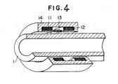
- the transmitting/receiving coil 13 as shown in Fig. 4 is placed in the space between the d.c. coils 11 and 12 so as to face body 1.
- Separate transmitting and receiving coils may also be used, arranged opposite each other on either side of the body 1.
- Fig. 2 shows the exciting currents flowing through the d.c. coils 11 and 12.
- the arrow heads on the solid lines indicate the direction of the d.c. exciting currents.
- the greater parts of the d.c. magnetic flux generated by the d.c. coils 11 and 12 passes through the body 1 parallelto the surface of the body in a longitudinal direction. That is, almost all of the magnetic flux generated by the coils 11 and 12 concentrates in a magnetic field that is parallel to the surface of the body 1.
- the intensity of the magnetic field increases as the ampere-turns of the d.c.
- the present embodiment is about 11 times as sensitive to longitudinal electromagnetic-acoustic waves as are conventional apparatuses. This is because the strength of transmitter/receiver signals increases according to the relation (1/0.3) 2 , where 0.3 tesla (3,000 gauss) refers to the average field intensity obtainable with conventional apparatuses.
- the transmitting/receiving coil 13 may be placed on the front, back, or side surface of the body 1 to be inspected so long as it is placed in the magnetic field. It is also possible to place more than one transmitting/ receiving coil in the magnetic field. To increase the efficiency with which a magnetic field is generated an iron core is present.
- Fig. 3 shows a perspective view of the complete embodiment. In Fig. 3, the iron core 14 is placed so as to enclose the d.c. coils 11 and 12.
- the intensity of the magnetic field in the body 1 can be increased much more and, therefore, sensitivity can also be greatly increased.
- Fig. 4 shows another embodiment of the present invention, in which the thickness of the wall of pipe 1 can be measured.
- Fig. 5 and 6 are side and front views respectively, in partial cross section, of the embodiment shown in Fig. 4.
- the figures show the structure of the embodiment in detail.
- the iron core 14 is divided into two symmetrical parts 14a and 14b, each of which is U-shaped in cross section and has several holes drilled through its mid-section, to allow other components of the apparatus to be attached.
- the d.c. coils 11 and 12 are secured to the 14a and 14b inner surfaces of the cores with protective covers 21 a and 21 b.
- the iron cores 14a and 14b are attached to each other with bolts 22 and nuts (not shown) sothatthed.c. coils 11 and 12 face each other.
- the cylindrical pole pieces 25a and 25b which have tapered heads, are placed in the holes that were drilled into the iron cores 14a and 14b and then fixed to the cores with bolts 26.
- the circular plates 27a and 27b which have holes drilled through their centers, serve as covers.
- the covers 27a and 27b have holes to allow the bolts 26 to pass through and thus hold the covers 27a and 27b and the pole pieces 25a and 25b to the cores 14a and 14b.
- the covers 27a and 27b also have several cut-outs to make way for cooling water pipes leading to the pole pieces 25a and 25b. Since each of the pole pieces 25a and 25b has the tapered head portion, it is possible to concentrate a magnetic field between the head portions. Accordingly, a magnetic field parallel to the surface of the body 1 to be measured can be effectively formed. When the size of the body 1 varies, the pole pieces 25a and 25b are replaced by other appropriate pole pieces.
- each of the pole pieces 25a and 25b is inclined as shown in Fig. 5, that is, has the form of a funnel, the body 1 can be smoothly inserted into the pole piece. Further, by bonding a protection member to the inner surface of the pole piece, the body 1 and pole pieces 25a and 25b are prevented from being damaged even if the body 1 strikes against the pole pieces 25a and 25b.
- Through-holes are provided in each of the pole pieces 25a and 25b to allow cooling water to flow, thereby cooling the pole pieces.
- Cooling water flows into an inlet pipe 28a, and then flows through a firstthrough-hole in the pole piece 25a.
- the cooling water having passed through the first through-hole is led at the head portion of the pole piece to a second through-hole, which is provided in the pole piece 25a so as to be spaced 90° apart from the first through-hole, through a connecting pipe (not shown).
- the cooling water having passed through the second through-hole is led to a third through-hole, which is provided 90° apart from the second through-hole, through a connecting pipe 30a.
- the cooling is provided inlet pipe 28a, and then flows through a firstthrough-hole in the pole piece 25a.
- the cooling water having passed through the first through-hole is led at the head portion of the pole piece to a second through-hole, which is provided in the pole piece 25a so as to be spaced 90° apart from the first through-
- cooling water having flowed through the third through-hole is led at the head portion of the pole piece to a fourth through-hole, which is provided 90° apart from the third through-hole, through a connecting pipe 31a.
- the cooling water having passed through the fourth through-hole is exhausted to the outside through an exit pipe (not shown) which is placed at an upper symmetrical position corresponding to the position of the inlet pipe 28a. That is, the pole piece 25a is provided therein with four parallel through-holes in such a manner that adjacent through-holes are spaced 90° apart from each other, and the cooling water flows through these through-holes to cool the pole piece 25a.
- cooling water flows into an inlet pipe 28b, flows through through-holes in the iron core 25b and connecting pipes (including a connecting pipe 31b), and is then exhausted through an exit pipe (not shown).
- each of the pole pieces 25a and 25b may be divided along a broken line into inner and outer cylinders, which are then united in one body:
- the inner and outer cylinders can be separately handled. Since each of these cylinders is small in weight as compared with the united pole piece, the replacement of pole piece becomes easy.
- a cylindrical block 40 for mounting therein transmitting/receiving parts is made of a flat hollow member and has through-holes 61 to 66 at an interval of 60°. Transmitting/receiving parts 51 to 56 are mounted in the through-holes 61 to 66, respectively. Incidentally, the through-holes 64 and 65 and transmitting/receiving parts 54 and 55 are not shown in Fig. 6.
- the block 40 is supported by respective head portions of the pole pieces 25a and 25b.
- the through-holes 61 to 66 provided in the block 40 are provided, on the side of the body 1, with non-conductive covers 71 to 76, respectively, and are provided, on the opposite side, with the transmitting/receiving parts 51 to 56, respectively. Since each transmitting/receiving part is mainly formed of, for example, moulded transmitting and receiving coils (not shown), protection covers 81 to 86 are disposed to reinforce the transmitting/receiving parts 51 to 56.
- cables 91 to 96 Electrical connections between an external circuit and every pair of transmitting and receiving coils are made by cables 91 to 96.
- the cables 91 to 96 are led to the outside through a through-hole provided in the pole piece 25b, in the same manner as an inlet pipe 42 mentioned later.
- the non-conductive covers 74 and 75, protection covers 84 and 85, and cables 94 and 95 are not shown in Fig. 6.
- the inlet pipe 42 is connected to a hollow portion 41 of the block 40 to introduce cooling water into the block 40.
- the cooling water thus introduced is divided at the hollow portion 41 into two parts, one of which flows into a space between the cover 71 and transmitting/receiving part 51, and the other flows into a space between the cover 72 and transmitting/receiving parts 52.
- the divided cooling water thus flows through hollow portions and spaces, and is then exhausted to the outside through an exit pipe (not shown) which is provided at a position opposite to that of the inlet pipe 42.
- the inlet pipe 42 passes through a through-hole 43 provided in the pole piece 25b, and the exit pipe passes through another through-hole.
- the inlet pipe 42 and the hollow portion 41 of the block 40 are small in cross section. Accordingly, when an impurity is mixed into the cooling water or an alga is generated therein, the inlet pipe 42 and hollow portion 41 may be clogged or the flow of cooling water in these members 41 and 42 may be put to one side. Thus, there is very fair possibility of insufficient cooling. Therefore, it ispreferable to use distilled water as the cooling water and to cause the cooling water to flow at a sufficiently high speed.
Landscapes
- Physics & Mathematics (AREA)
- General Physics & Mathematics (AREA)
- Electromagnetism (AREA)
- Health & Medical Sciences (AREA)
- Life Sciences & Earth Sciences (AREA)
- Chemical & Material Sciences (AREA)
- Analytical Chemistry (AREA)
- Biochemistry (AREA)
- General Health & Medical Sciences (AREA)
- Immunology (AREA)
- Pathology (AREA)
- Investigating Or Analyzing Materials By The Use Of Ultrasonic Waves (AREA)
Claims (6)
Applications Claiming Priority (6)
| Application Number | Priority Date | Filing Date | Title |
|---|---|---|---|
| JP56088188A JPS57203949A (en) | 1981-06-10 | 1981-06-10 | Electromagnetic ultrasonic flaw detector |
| JP88188/81 | 1981-06-10 | ||
| JP88189/81 | 1981-06-10 | ||
| JP56088189A JPS57203950A (en) | 1981-06-10 | 1981-06-10 | Electromagnetic ultrasonic flaw detector |
| JP61126/82 | 1982-04-14 | ||
| JP6112682A JPS58179305A (ja) | 1982-04-14 | 1982-04-14 | 電磁超音波計測装置 |
Publications (2)
| Publication Number | Publication Date |
|---|---|
| EP0067065A1 EP0067065A1 (de) | 1982-12-15 |
| EP0067065B1 true EP0067065B1 (de) | 1987-01-28 |
Family
ID=27297396
Family Applications (1)
| Application Number | Title | Priority Date | Filing Date |
|---|---|---|---|
| EP82302944A Expired EP0067065B1 (de) | 1981-06-10 | 1982-06-08 | Elektromagnetisch-akustischer Messapparat |
Country Status (3)
| Country | Link |
|---|---|
| US (1) | US4450725A (de) |
| EP (1) | EP0067065B1 (de) |
| DE (1) | DE3275315D1 (de) |
Cited By (1)
| Publication number | Priority date | Publication date | Assignee | Title |
|---|---|---|---|---|
| US12123232B2 (en) | 2018-09-23 | 2024-10-22 | Dan Raz Ltd. | Panel lock assembly |
Families Citing this family (19)
| Publication number | Priority date | Publication date | Assignee | Title |
|---|---|---|---|---|
| DE3401072C2 (de) * | 1984-01-13 | 1986-04-10 | Nukem Gmbh, 6450 Hanau | Elektrodynamischer Wandlerkopf |
| DE3601373A1 (de) * | 1985-01-22 | 1986-08-28 | Siderca S.A. Industrial y Comercial, Capital Federal | Vorrichtung zur dickenmessung mit hilfe von ultraschall |
| FR2585869B1 (fr) * | 1985-08-01 | 1987-11-13 | Fragema Framatome & Cogema | Procede et dispositif de controle des crayons de grappe pour assemblage de combustible nucleaire. |
| DE3629174A1 (de) * | 1986-08-28 | 1988-03-10 | Ktv Systemtechnik Gmbh | Einrichtung zum messen der wanddicke von rohren |
| ATE78926T1 (de) * | 1987-05-23 | 1992-08-15 | Siemens Ag | Vorrichtung zur pruefung eines rohres. |
| DE3935432A1 (de) * | 1989-10-20 | 1991-04-25 | Mannesmann Ag | Vorrichtung zur zerstoerungsfreien pruefung von werkstuecken |
| US5895856A (en) * | 1994-08-02 | 1999-04-20 | The United States Of America As Represented By The Secretary Of Commerce | Electromagnetic acoustic transducer and methods of determining physical properties of cylindrical bodies using an electromagnetic acoustic transducer |
| US6119522A (en) * | 1994-08-02 | 2000-09-19 | The United States Of America As Represented By The Secretary Of Commerce | Electromagnetic acoustic transducer and methods of determining physical properties of cylindrical bodies using an electromagnetic acoustic transducer |
| DE19628028A1 (de) * | 1996-07-11 | 1998-01-22 | Siemens Ag | Prüfvorrichtung und Verfahren zur zerstörungsfreien Werkstoffprüfung |
| US5808202A (en) * | 1997-04-04 | 1998-09-15 | Passarelli, Jr.; Frank | Electromagnetic acoustic transducer flaw detection apparatus |
| DE102004053584B4 (de) * | 2004-11-05 | 2006-08-31 | Fraunhofer-Gesellschaft zur Förderung der angewandten Forschung e.V. | Vorrichtung und Verfahren zur Materialprüfung und/oder Dickenmessung an einem wenigstens elektrisch leitende und ferromagnetische Materialanteile aufweisenden Prüfobjekt |
| US7501814B2 (en) * | 2006-09-07 | 2009-03-10 | Southwest Research Institute | Apparatus and method for second-layer through-bushing inspection of aircraft wing attachment fittings using electric current perturbation |
| US8707625B2 (en) | 2011-06-28 | 2014-04-29 | Dan Raz Ltd. | Arrangement for securing a panel closure |
| US8806950B2 (en) | 2011-11-09 | 2014-08-19 | The Boeing Company | Electromagnetic acoustic transducer system |
| CN102954774B (zh) * | 2012-10-26 | 2014-12-31 | 华中科技大学 | 一种基于聚磁桥路的钢管壁厚电磁超声测量装置 |
| GB201419219D0 (en) * | 2014-10-29 | 2014-12-10 | Imp Innovations Ltd | Electromagnetic accoustic transducer |
| US9970214B2 (en) | 2015-11-29 | 2018-05-15 | Dan Raz Ltd | Door or other closable panel with lock-actuating linkage |
| US9988830B2 (en) | 2016-03-03 | 2018-06-05 | Dan Raz Ltd. | Latch arrangement having a handle |
| US10487545B2 (en) | 2016-03-03 | 2019-11-26 | Dan Raz Ltd. | Latch arrangement having a stop latch |
Citations (1)
| Publication number | Priority date | Publication date | Assignee | Title |
|---|---|---|---|---|
| JPS5631637A (en) * | 1979-08-24 | 1981-03-31 | Nippon Steel Corp | Instrument unit of electromagnetic ultrasonic wave |
Family Cites Families (10)
| Publication number | Priority date | Publication date | Assignee | Title |
|---|---|---|---|---|
| US3586963A (en) * | 1969-04-03 | 1971-06-22 | Ford Motor Co | Magnetically determining mechanical properties of moving ferromagnetic materials |
| US3697867A (en) * | 1969-06-19 | 1972-10-10 | Cavitron Corp | Vibration sensor utilizing eddy currents induced in member vibrating in the field of a magnet |
| SE347356B (de) * | 1970-03-20 | 1972-07-31 | Essem Metotest Ab | |
| US3963980A (en) * | 1973-08-29 | 1976-06-15 | Jury Mikhailovich Shkarlet | Ultrasonic instrument for non-destructive testing of articles with current-conducting surface |
| FR2288619A1 (fr) * | 1974-10-23 | 1976-05-21 | Nippon Electric Co | Dispositif de commande d'un fil d'impression pour une imprimante a matrice a points |
| SU543868A1 (ru) * | 1975-11-03 | 1977-01-25 | Челябинский политехнический институт им. Ленинского комсомола | Электромагнитоакустический преобразователь |
| GB2008756B (en) * | 1977-09-30 | 1982-07-14 | Ti Group Services Ltd | Ultrasonic inspection |
| US4184374A (en) * | 1978-06-22 | 1980-01-22 | Rockwell International Corporation | Ultrasonic inspection of a cylindrical object |
| US4309905A (en) * | 1979-12-26 | 1982-01-12 | Maizenberg Mikhail I | Method for detecting non-uniformities of magnetic materials and device for effecting same |
| IT1129066B (it) * | 1980-02-26 | 1986-06-04 | Fiat Ricerche | Dispositivo per misura non distruttiva dello spessore di uno strato superficiale di un corpo sottoposto ad un trattamento di modifica della propria struttura superficiale |
-
1982
- 1982-06-08 DE DE8282302944T patent/DE3275315D1/de not_active Expired
- 1982-06-08 EP EP82302944A patent/EP0067065B1/de not_active Expired
- 1982-06-09 US US06/386,445 patent/US4450725A/en not_active Expired - Lifetime
Patent Citations (2)
| Publication number | Priority date | Publication date | Assignee | Title |
|---|---|---|---|---|
| JPS5631637A (en) * | 1979-08-24 | 1981-03-31 | Nippon Steel Corp | Instrument unit of electromagnetic ultrasonic wave |
| US4348903A (en) * | 1979-08-24 | 1982-09-14 | Nippon Steel Corporation | Electromagnetic ultrasonic apparatus |
Cited By (1)
| Publication number | Priority date | Publication date | Assignee | Title |
|---|---|---|---|---|
| US12123232B2 (en) | 2018-09-23 | 2024-10-22 | Dan Raz Ltd. | Panel lock assembly |
Also Published As
| Publication number | Publication date |
|---|---|
| US4450725A (en) | 1984-05-29 |
| DE3275315D1 (en) | 1987-03-05 |
| EP0067065A1 (de) | 1982-12-15 |
Similar Documents
| Publication | Publication Date | Title |
|---|---|---|
| US4450725A (en) | Electromagnetic-acoustic measuring apparatus | |
| US5689070A (en) | High temperature electromagnetic acoustic transducer (EMAT) probe and coil assemblies | |
| EP0621954B1 (de) | Bestimmung von gesteinkern-charakteristiken | |
| EP0239537B1 (de) | Verfahren und Vorrichtung zur Prüfung eines metallischen Seils | |
| US10983096B2 (en) | Guided wave testing | |
| EP0332048A3 (de) | Wirbelstromsonde mit mehreren Spulen und Verfahren zur Feststellung von Fehlstellen | |
| US3940996A (en) | Method and device for remotely monitoring electrically conductive liquids | |
| US3119960A (en) | Electromagnetic marine speedometer mounted substantially flush with an outer surface of a ship | |
| KR20140019160A (ko) | 전자기 유도방식의 누설자속 검출유닛, 이를 이용한 비파괴 검사 시스템 및 검사 방법 | |
| US7434467B2 (en) | Electromagnetic ultrasound converter | |
| US2895103A (en) | Magnetic testing apparatus | |
| US4281552A (en) | Electromagnetic flowmeter | |
| US3872379A (en) | Eddy current testing apparatus using slotted monoturn conductive members | |
| GB2031155A (en) | Isotropic magnetising system | |
| IE47295B1 (en) | Ultrasonic testing | |
| US3444458A (en) | Device for detecting variations in magnetic properties of ferromagnetic material | |
| US11692969B2 (en) | Apparatus and method for measuring magnetic properties of a ferromagnetic endless belt | |
| JPH0146028B2 (de) | ||
| US4864236A (en) | Wire inhomogeneity detector having a core with opposing pole pieces and guide pieces adjacent the opposing pole pieces | |
| JPS5621058A (en) | Transducer for electromagnetic supersonic wave flaw detection | |
| SE445616B (sv) | Forfarande att introducera elektromagnetiskt ultraljud i elektriskt ledande material vid oforstorande provning samt anordning for utforande av forfarandet | |
| RU2279671C1 (ru) | Устройство для ультразвукового контроля изделий из электропроводных материалов | |
| US3189817A (en) | Device for testing metal sheets by measuring the time required for electromagnetic pulses to pass therethrough | |
| US20250389755A1 (en) | Planar sensor and electric current sensor | |
| JPS6070352A (ja) | 電磁超音波トランスデュ−サ |
Legal Events
| Date | Code | Title | Description |
|---|---|---|---|
| PUAI | Public reference made under article 153(3) epc to a published international application that has entered the european phase |
Free format text: ORIGINAL CODE: 0009012 |
|
| AK | Designated contracting states |
Designated state(s): CH DE FR GB IT LI NL SE |
|
| 17P | Request for examination filed |
Effective date: 19830613 |
|
| GRAA | (expected) grant |
Free format text: ORIGINAL CODE: 0009210 |
|
| AK | Designated contracting states |
Kind code of ref document: B1 Designated state(s): CH DE FR GB IT LI NL SE |
|
| PG25 | Lapsed in a contracting state [announced via postgrant information from national office to epo] |
Ref country code: NL Effective date: 19870128 Ref country code: LI Effective date: 19870128 Ref country code: CH Effective date: 19870128 |
|
| REF | Corresponds to: |
Ref document number: 3275315 Country of ref document: DE Date of ref document: 19870305 |
|
| ITF | It: translation for a ep patent filed | ||
| ET | Fr: translation filed | ||
| REG | Reference to a national code |
Ref country code: CH Ref legal event code: PL |
|
| NLV1 | Nl: lapsed or annulled due to failure to fulfill the requirements of art. 29p and 29m of the patents act | ||
| PLBE | No opposition filed within time limit |
Free format text: ORIGINAL CODE: 0009261 |
|
| STAA | Information on the status of an ep patent application or granted ep patent |
Free format text: STATUS: NO OPPOSITION FILED WITHIN TIME LIMIT |
|
| 26N | No opposition filed | ||
| PGFP | Annual fee paid to national office [announced via postgrant information from national office to epo] |
Ref country code: SE Payment date: 19890509 Year of fee payment: 8 |
|
| PG25 | Lapsed in a contracting state [announced via postgrant information from national office to epo] |
Ref country code: SE Effective date: 19900609 |
|
| ITTA | It: last paid annual fee | ||
| EUG | Se: european patent has lapsed |
Ref document number: 82302944.2 Effective date: 19910206 |
|
| PGFP | Annual fee paid to national office [announced via postgrant information from national office to epo] |
Ref country code: GB Payment date: 20010405 Year of fee payment: 20 |
|
| PGFP | Annual fee paid to national office [announced via postgrant information from national office to epo] |
Ref country code: FR Payment date: 20010418 Year of fee payment: 20 |
|
| PGFP | Annual fee paid to national office [announced via postgrant information from national office to epo] |
Ref country code: DE Payment date: 20010607 Year of fee payment: 20 |
|
| REG | Reference to a national code |
Ref country code: GB Ref legal event code: IF02 |
|
| PG25 | Lapsed in a contracting state [announced via postgrant information from national office to epo] |
Ref country code: GB Free format text: LAPSE BECAUSE OF EXPIRATION OF PROTECTION Effective date: 20020607 |