EP0067331A2 - Appareil pour couper des carcasses d'animaux de boucherie en moitiés au moyen d'une scie à ruban - Google Patents
Appareil pour couper des carcasses d'animaux de boucherie en moitiés au moyen d'une scie à ruban Download PDFInfo
- Publication number
- EP0067331A2 EP0067331A2 EP82104608A EP82104608A EP0067331A2 EP 0067331 A2 EP0067331 A2 EP 0067331A2 EP 82104608 A EP82104608 A EP 82104608A EP 82104608 A EP82104608 A EP 82104608A EP 0067331 A2 EP0067331 A2 EP 0067331A2
- Authority
- EP
- European Patent Office
- Prior art keywords
- saw
- band
- suction cups
- animal body
- band saw
- Prior art date
- Legal status (The legal status is an assumption and is not a legal conclusion. Google has not performed a legal analysis and makes no representation as to the accuracy of the status listed.)
- Withdrawn
Links
Images

Classifications
-
- A—HUMAN NECESSITIES
- A22—BUTCHERING; MEAT TREATMENT; PROCESSING POULTRY OR FISH
- A22B—SLAUGHTERING
- A22B5/00—Accessories for use during or after slaughtering
- A22B5/20—Splitting instruments
- A22B5/202—Guides or devices for holding the carcass during the splitting operation
-
- A—HUMAN NECESSITIES
- A22—BUTCHERING; MEAT TREATMENT; PROCESSING POULTRY OR FISH
- A22B—SLAUGHTERING
- A22B5/00—Accessories for use during or after slaughtering
- A22B5/20—Splitting instruments
- A22B5/203—Meat or bone saws for splitting carcasses
- A22B5/206—Disc or circular saws
Definitions
- the invention relates to a device according to the preamble of claim 1.
- Halving carcasses with the aid of circular saws, jigsaws and splitting knives, halving with the aid of a band saw advantageously differs in that the sawing tool does not tend to smear, that the entire carcass can be easily halved in a single sawing operation and that compared to halving much less forces have to be applied with a splitting knife.
- Halving carcasses with the aid of a band saw is known from US Pat. No. 3,790,989.
- This known device works with a stationary band saw, the saw band of which is guided essentially rectangularly over four disks.
- the carcass to be halved is hung on its rear legs with two hooks, and the hooks can be on two rails be rolled on.
- the respective carcass is brought into engagement with the stationary band saw by moving the hooks and halved while moving. It has been shown that the animal body hanging freely on the hook is not always cut in half cleanly in the middle, since its spine often does not hang sufficiently precisely in the direction of the sawing process, and because the free-hanging animal body is used for commuting and for uncontrolled evasion under the action of the saw band tends.
- the invention has for its object to provide a device of the type mentioned for the exact halving of carcasses in their spine.
- the device is designed according to the invention as specified in the characterizing part of claim 1.
- the respective animal body is held in position during the sawing process, so that the conditions for an exactly lying sawing process are favorable.
- suction cups for this purpose has proven to be favorable, since they are suitable for keeping the animal body, which is unstable in itself, unstable, "wobbly", particularly in the case of slaughtered pigs, in its position.
- the movement of the band saw and the suction cups with the respective carcass creates constant conditions for the entire sawing process. Since the band saw is fed for the sawing process essentially in the direction of the spine and since the respective sawing section of the saw band can be kept much shorter, for example extending only from the abdominal side to the back of the slaughter animal, there is a risk of undesired development
- the carcasses are preferably suspended from the hind legs on hooks that spread the hind legs of the respective carcass.
- the further movement of the animal bodies is preferably carried out by moving the hooks on a suitable path, the further movement preferably taking place in the transverse direction of the animal bodies.
- the carcasses are preferably halved from top to bottom with the band saw.
- suction cups are provided along each side of the spine of the animal body. This results in an even more precise res holding the carcass during the sawing process.
- the suction cups provided on both sides of the spine are preferably arranged in a V-shape in plan view, which is also conducive to the stability of the position fixation.
- the suction cups are preferably held by a suction cup support frame and the suction cup support frame can be approached to and removed from the respective animal body.
- the suction cups are movable in their axial direction.
- the suction cups in their axial direction, perpendicular to say in a direction substantially toward the T ier Sciences contacting surface of the respective suction cup, according to the progress of the cutting operation in order, preferably in pairs, withdrawn on both sides of the spine while maintaining the negative pressure.
- the animal body behind the saw band moving forward in the direction of the sawing process is pulled apart in a wedge-like manner, as a result of which a cleaner sawing process is achieved without any risk of the saw band becoming jammed.
- suction cups can be pivoted individually or per row of suction cups provided on each side of the spine, preferably about a vertical axis.
- the suction cups can be optimally adjusted to the shape of the animal body len, in extreme cases even make this adjustment to each individual animal body. It is also possible to use the movement possibilities of the suction cups just described instead of the movement possibility according to claim 4 or in addition to this for introducing them into the movement path of the animal bodies and for moving them out of the movement path of the animal bodies.
- the saw band can be guided very simply; it is preferably guided around two disks, the disk located on the belly side of the animal body being driven and the other disk being a pure deflection disk.
- the two saw band sections thus formed are preferably one above the other, so that the non-sawing section runs back in the gap created by the sawing process.
- a particularly good, generally additional guidance of the band saw can be achieved by equipping the band saw with a pair of rollers rolling off the back of the respective animal body, the peripheral surfaces of which form a guide space which widens in the direction of the animal body. This results in self-centering guidance.
- the pair of rollers is preferably resiliently connected to the free end region of the band saw facing away from the drive.
- the device is provided with a suitable control device, the design of which lies within the scope of expert knowledge.
- the control device ensures that the suction cups are brought into contact with the animal body in a newly arriving animal body, the band saw is advanced until the saw band extends from the belly side of the animal body to the back side through the spread legs, the band saw is put into operation the band saw for the sawing process is moved in the longitudinal direction of the animal body, the band saw is moved back to the starting point of the sawing process, the band saw is moved back outside the travel path of the animal body, the suction cups are moved back and finally the band saw and the suction cups are moved counter to the direction of travel of the animal body be driven back so that they are ready there for the next arriving carcass.
- the individual phases of the workflow can be controlled by position switches and / or timers.
- the device according to the invention can work fully automatically, so that operating personnel are required at most for monitoring tasks.
- the band saw and the suction cups can also stop the further movement of the carcasses during the sawing process and accordingly do not move the band saw and the suction cups.
- Another possibility is to remove the animal body to be sawn from the general path of travel by means of a switch, to saw there in the non-moved state and then to re-insert it into the general path of travel.
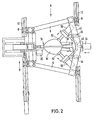
- the device has a frame 2, which essentially consists of four vertical rods 4, arranged in plan view at the corner points of an imaginary trapezoid, and three, the lower ends of the rods 4 on the belly side of the pig carcass 10 and in its direction of movement in front of and behind the pig carcass 10 interconnecting, horizontal rods 6 there.
- Each rod 4 is provided at its upper end on the outside with a roller 8 with an angular profile of its circumference.
- the two rollers 8 assigned to the belly side of the pig carcass 10 run on a correspondingly profiled rail 12, while the two rollers 8 assigned to the back side of the pig carcass 10 roll on a further, correspondingly profiled rail 12.
- the two rails 12 are arranged on both sides and parallel to a tube 14 on which hooks 16 with pig bodies 10 hanging thereon can be moved on.
- a pig body 10 hangs with a rear leg on a hook 16 such that the rear legs are spread.
- a conveyor chain (not shown) with a number of drivers runs above the tube 14. These reach behind the hooks 16 so that the pig bodies 10 are moved further in the direction of the tube 14 in this way.
- a rod is pneumatically extended transversely to the direction of further movement of the pig body 10 in such a way that it is taken along by a driver of the conveyor chain and in turn takes the entire frame 2 with it.
- a cylinder-piston unit is used to move the frame 2 back after the sawing process has ended.
- a band saw carriage 18 On the belly side of the pig body 10, a band saw carriage 18 is provided, which is guided with rollers on the two vertical bars 4 assigned to the belly side of the pig body 10 and can be moved up and down along the bars 4.
- the corresponding drive is provided by a pneumatic cylinder-piston unit 20, which is arranged vertically between the two belly rods 4.
- the band saw carriage 18 carries a horizontal carriage 22 on which the actual band saw 24 is attached between the bars 4.
- the horizontal carriage 22 is by means of a pneumatic cylinder-piston unit 26, which is supported on the band saw carriage 18 and in Fig. 1 behind the left rod 4 with the horizontal carriage 22, in the horizontal direction between a rest position in which the Band saw 24 is located completely on the belly side of the pig body 10, and an operating position in which the band saw extends from the belly side to the back side over the entire pig body 10.
- the band saw 24 has two deflection disks of the same diameter, not shown separately, around which the saw band 28 is guided, a band saw frame holding the two disks, not shown separately, and an electric motor 30 for driving the band saw.
- the electric motor 30 is located between the belly rods 4 and the pig body 10.
- a lever 32 protrudes from the band saw frame.
- the piston rod of a pneumatic cylinder-piston unit 34 is articulated at the upper end of the lever 32.
- the lever 32 and thus the band saw frame can be pivoted about a horizontal axis, which coincides with the axis of the belly-side deflection disk of the saw band 28, in such a way that the saw band 28, seen from the belly side of the pig body 10 , diagonally upwards, essentially horizontally, or diagonally downwards.
- the cylinder of the cylinder-piston unit 34 is fixed on the horizontal carriage 22.
- a suction cup support frame 39 is carried by the two rods 4 assigned to the rear side of the pig body 10 and essentially consists of an upper angle plate 40 leading from one rod 4 to the other rod 4, a corresponding lower angle plate and one connecting the two horizontal angle plates , vertical plate 42 is made.
- the upper angle plate 40 is provided a little below the upper ends of the two associated rods 4, and the lower angle plate 40 is provided a little above the lower ends of the two associated rods 4.
- the angle plates 40 each have two legs which are symmetrical to one another and which form an angle of approximately 150 ° with one another.
- the vertical Plate 42 is connected to the angle plates 40 at the points of this change in angle.
- the cylinder of a pneumatic cylinder-piston unit 44 is carried by the vertical plate 42, the piston rod of which acts on a vertical support 46.
- Two support plates 48 extend from the support 46 in a V-shape towards the pig body 10.
- four pneumatic cylinder-piston units 50 are attached at right angles to one another, with each piston rod carrying a suction cup 52 on the inside. Two rows of suction cups 52 are thus formed, which are aimed at the pig body 10 in a V-shape.
- two pneumatic cylinder-piston units 54 are effective, with which the Support plates 48 are pivotable about a vertical axis relative to the carrier 46.
- the suction cups 52 With the cylinder-piston unit 44, the suction cups 52 as a whole can be approached or removed from the pig body 10.
- the suction cups 52 With the cylinder-piston units 50, the suction cups 52 can be individually approached to the pig carcass 10, retracted with the pig carcass half sucked in and removed from the pig carcass, and the suction cups 52 can be individually adjusted to the contour of the pig carcass 10.
- the suction cups 52 With the cylinder-piston units 54, the suction cups 52 can be pivotally approached or removed from the pig body 10 or adjusted to the shape of the pig body 10.
- the suction cup support frame 38 can be moved vertically along the two associated rods 4 by means of a pneumatic cylinder-piston unit (not shown).
- a working cycle of the device can, for example, proceed as follows: In a starting position of the frame 2, when a pig body 10 is centered in relation to the belt saw 24 is located and this is detected by switches, the movement of the frame 2 synchronously and in parallel with the movement of the pig body 10 along the tube 14 switched on. Then the horizontal carriage 22 is advanced so far that the non-driven deflection disc is located between the back of the pig carcass and the two rods 4 assigned to the back of the pig carcass 10. The lower section of the saw band intended for sawing, starting from the driven deflection disk, runs upwards at an angle of approximately 30 °. Then the feed of the band saw carriage 18 is turned on in the vertical direction downward.
- the band saw frame is pivoted downward until the sawing section of the saw band lies approximately horizontally or points upwards at a slight angle.
- the band saw frame is inclined with its free end downwards until the sawing section of the saw band, starting from the driven deflection disk, is inclined downward at an angle of approximately 30 to 45 °.
- the suction cup pairs are moved backwards in order from the top downwards with the corresponding cylinder / piston units 50 in order to open the pig body 10 from top downwards. Then the band saw carriage 18 is moved back upwards, while simultaneously pivoting the band saw frame upwards.
- the horizontal slide 22 together with the band saw 24 is then moved back transversely to the direction of movement A of the pig body 10.
- the suction cups 52 which were initially advanced at the same time as the band saw 24 with the aid of the cylinder-piston unit 44 transversely to the direction A of the pig carcass 10 until they came into contact with the pig carcass 10, are now switched off with the cylinder Piston unit 44 retracted in the opposite direction, so that the pig body 10 now hangs freely on the hook 16. Now the frame 2 is in total against the direction of movement A.
- the pig body 10 in the off retracted position where the next cycle can start with a new pig body 10.
- the pig carcasses 10 move laterally along the tube 14 and the two sections of the saw band 28 are located vertically one above the other between the deflection disks.
- the sawing direction of the sawing section of the saw band 28 is preferably selected from the belly side of the pig body 10 to the rear side thereof, so that the sawing forces press the pig body 10 against the suction cups 52 and the rollers 38.
- a roller-like roller running on the belly side of the pig body 10 below the band saw 24 can be provided.
- the saw band is rotated 90 ° behind or in front of the deflection disks by small rollers so that it can be deflected on the deflection disks.
Landscapes
- Life Sciences & Earth Sciences (AREA)
- Engineering & Computer Science (AREA)
- Food Science & Technology (AREA)
- Processing Of Meat And Fish (AREA)
- Sawing (AREA)
Applications Claiming Priority (2)
| Application Number | Priority Date | Filing Date | Title |
|---|---|---|---|
| DE3123439 | 1981-06-12 | ||
| DE19813123439 DE3123439A1 (de) | 1981-06-12 | 1981-06-12 | Vorrichtung zum halbieren von schlachttierkoerpern mittels einer bandsaege |
Publications (2)
| Publication Number | Publication Date |
|---|---|
| EP0067331A2 true EP0067331A2 (fr) | 1982-12-22 |
| EP0067331A3 EP0067331A3 (fr) | 1984-02-22 |
Family
ID=6134603
Family Applications (1)
| Application Number | Title | Priority Date | Filing Date |
|---|---|---|---|
| EP82104608A Withdrawn EP0067331A3 (fr) | 1981-06-12 | 1982-05-26 | Appareil pour couper des carcasses d'animaux de boucherie en moitiés au moyen d'une scie à ruban |
Country Status (3)
| Country | Link |
|---|---|
| EP (1) | EP0067331A3 (fr) |
| DE (1) | DE3123439A1 (fr) |
| ES (1) | ES8305192A1 (fr) |
Cited By (8)
| Publication number | Priority date | Publication date | Assignee | Title |
|---|---|---|---|---|
| US4706335A (en) * | 1986-10-03 | 1987-11-17 | Wolverine World Wide, Inc. | Hog splitter |
| WO1989005584A1 (fr) * | 1987-12-23 | 1989-06-29 | Commonwealth Scientific And Industrial Research Or | Traitement automatique d'animaux |
| US5139457A (en) * | 1987-12-23 | 1992-08-18 | Commonwealth Scientific & Industrial Research Organization | Automatic animal processing |
| AU632230B2 (en) * | 1987-12-23 | 1992-12-17 | Australian Meat & Livestock Research & Development Corporation | Automatic animal carcass splitting |
| US5195923A (en) * | 1987-12-23 | 1993-03-23 | Commonwealth Scientific & Industrial Research Organization | Automatic animal processing |
| EP1196036A4 (fr) * | 1999-07-01 | 2002-10-23 | Jarvis Products | Scie automatique pour fendre des carcasses |
| CN115336619A (zh) * | 2022-08-11 | 2022-11-15 | 河北金宏清真肉类有限公司 | 一种屠宰用割断分离装置 |
| CN115385077A (zh) * | 2022-08-19 | 2022-11-25 | 中科定洋农业集团有限公司 | 一种羊肉生产定位引导装置 |
Family Cites Families (2)
| Publication number | Priority date | Publication date | Assignee | Title |
|---|---|---|---|---|
| DE1220284B (de) * | 1962-06-29 | 1966-06-30 | Schmid & Wezel | Bandsaege, insbesondere zum Trennen von Grossviehkoerpern |
| JPS553770A (en) * | 1977-07-19 | 1980-01-11 | Nobuo Koyama | Apparatus for dividing back of slaughtered body |
-
1981
- 1981-06-12 DE DE19813123439 patent/DE3123439A1/de not_active Ceased
-
1982
- 1982-05-26 EP EP82104608A patent/EP0067331A3/fr not_active Withdrawn
- 1982-06-11 ES ES514249A patent/ES8305192A1/es not_active Expired
Cited By (11)
| Publication number | Priority date | Publication date | Assignee | Title |
|---|---|---|---|---|
| US4706335A (en) * | 1986-10-03 | 1987-11-17 | Wolverine World Wide, Inc. | Hog splitter |
| WO1989005584A1 (fr) * | 1987-12-23 | 1989-06-29 | Commonwealth Scientific And Industrial Research Or | Traitement automatique d'animaux |
| US5139457A (en) * | 1987-12-23 | 1992-08-18 | Commonwealth Scientific & Industrial Research Organization | Automatic animal processing |
| AU632230B2 (en) * | 1987-12-23 | 1992-12-17 | Australian Meat & Livestock Research & Development Corporation | Automatic animal carcass splitting |
| US5195923A (en) * | 1987-12-23 | 1993-03-23 | Commonwealth Scientific & Industrial Research Organization | Automatic animal processing |
| US5312292A (en) * | 1987-12-23 | 1994-05-17 | Commonwealth Scientific & Industrial Research Organisation | Automatic animal processing |
| EP0508551B1 (fr) * | 1987-12-23 | 1995-07-19 | Commonwealth Scientific And Industrial Research Organisation | Appareillage pour fendre automatiquement les carcasses des animaux de boucherie |
| EP1196036A4 (fr) * | 1999-07-01 | 2002-10-23 | Jarvis Products | Scie automatique pour fendre des carcasses |
| CN115336619A (zh) * | 2022-08-11 | 2022-11-15 | 河北金宏清真肉类有限公司 | 一种屠宰用割断分离装置 |
| CN115385077A (zh) * | 2022-08-19 | 2022-11-25 | 中科定洋农业集团有限公司 | 一种羊肉生产定位引导装置 |
| CN115385077B (zh) * | 2022-08-19 | 2025-06-27 | 中科定洋农业集团有限公司 | 一种羊肉生产定位引导装置 |
Also Published As
| Publication number | Publication date |
|---|---|
| DE3123439A1 (de) | 1982-12-30 |
| ES514249A0 (es) | 1983-04-01 |
| EP0067331A3 (fr) | 1984-02-22 |
| ES8305192A1 (es) | 1983-04-01 |
Similar Documents
| Publication | Publication Date | Title |
|---|---|---|
| DE69630178T2 (de) | Verfahren und Vorrichtung zum Bearbeiten von Schlachtgeflügel | |
| DE2604244C2 (de) | Vorrichtung zum Anbringen eines Einschnitts nahe dem Bürzel von mit den Beinen an einem Transportbügel hängenden Schlachtgeflügel | |
| DE2530013C2 (de) | Verfahren und Vorrichtung zum selbsttätigen Ausweiden von ungeköpften Fischen | |
| DE69204254T2 (de) | Vorrichtung zum Trennen eines aus einem Geflügel entfernten Guts bestehend aus Eingeweiden, Leber und Herz mit Lungen. | |
| DE3854204T2 (de) | Vorrichtung zum automatischen Spalten von Schlachttierkörpern. | |
| DE2600766C2 (fr) | ||
| DE652383C (de) | Maschine zum Fischfiletschneiden | |
| DE1579329B1 (de) | Halbautomatische Vorrichtung zur Vorbereitung von Reifenlagen | |
| DE1931905U (de) | Vorrichtung zum herstellen von heizkoerpern in tafel- bzw. plattenform. | |
| DE2313092A1 (de) | Vorrichtung zur verarbeitung von gefluegel | |
| DE3123439A1 (de) | Vorrichtung zum halbieren von schlachttierkoerpern mittels einer bandsaege | |
| DE3247588C2 (de) | Vorrichtung zum Halbieren von Schlachttierkörpern durch Sägen | |
| EP0212580A2 (fr) | Dispositif pour trancher la tête des carcasses, en particulier des bovins | |
| DD212644A5 (de) | Vorrichtung zum koepfen gekehlter fische | |
| DE69017693T2 (de) | Verfahren und vorrichtung zum ausbeinen von schlachtbauchstücken. | |
| DE1939046C2 (de) | Vorrichtung zum Zweiteilen von Schlachtviehrümpfen | |
| DE3343789C2 (de) | Verfahren und Vorrichtung zum maschinellen Öffnen auch unterschiedlich großer Fische, insbesondere Forellen, und zum Entfernen der Eingeweide | |
| EP0212579B2 (fr) | Dispositif pour ouvrir la poitrine des carcasses, en particulier des bovins ou porcs | |
| DE69115453T2 (de) | Verfahren und vorrichtung zum entbeinen von köpfen eines schlachttierstückes | |
| DE10222754C1 (de) | Maschine zum Heraustrennen von Rippen aus Schweinebäuchen | |
| DE2421225A1 (de) | Vorrichtung zum spalten geschlachteter tierkoerper | |
| DD264141A5 (de) | Verfahren zum zerlegen von fischen und vorrichtung zur durchfuehrung des verfahrens | |
| DE19981451B4 (de) | Verfahren und Vorrichtung zur Verarbeitung von Fischen | |
| DE29603797U1 (de) | Maschine zum Entbeinen | |
| DE69001178T2 (de) | Vorrichtung zum entfernen der haelse von gefluegel. |
Legal Events
| Date | Code | Title | Description |
|---|---|---|---|
| PUAI | Public reference made under article 153(3) epc to a published international application that has entered the european phase |
Free format text: ORIGINAL CODE: 0009012 |
|
| AK | Designated contracting states |
Designated state(s): AT BE CH DE FR GB IT LI NL SE |
|
| PUAL | Search report despatched |
Free format text: ORIGINAL CODE: 0009013 |
|
| AK | Designated contracting states |
Designated state(s): AT BE CH DE FR GB IT LI NL SE |
|
| 17P | Request for examination filed |
Effective date: 19840822 |
|
| STAA | Information on the status of an ep patent application or granted ep patent |
Free format text: STATUS: THE APPLICATION HAS BEEN WITHDRAWN |
|
| 18W | Application withdrawn |
Withdrawal date: 19860102 |
|
| RIN1 | Information on inventor provided before grant (corrected) |
Inventor name: GERLACH, CURT |