EP0067367B1 - Système pour l'orientation magnétique - Google Patents
Système pour l'orientation magnétique Download PDFInfo
- Publication number
- EP0067367B1 EP0067367B1 EP82104844A EP82104844A EP0067367B1 EP 0067367 B1 EP0067367 B1 EP 0067367B1 EP 82104844 A EP82104844 A EP 82104844A EP 82104844 A EP82104844 A EP 82104844A EP 0067367 B1 EP0067367 B1 EP 0067367B1
- Authority
- EP
- European Patent Office
- Prior art keywords
- magnetic
- field
- orientating
- layer support
- travel
- Prior art date
- Legal status (The legal status is an assumption and is not a legal conclusion. Google has not performed a legal analysis and makes no representation as to the accuracy of the status listed.)
- Expired
Links
- 230000005291 magnetic effect Effects 0.000 title claims description 77
- 239000002245 particle Substances 0.000 claims description 31
- 239000000049 pigment Substances 0.000 claims description 24
- 238000005266 casting Methods 0.000 claims description 8
- 239000013598 vector Substances 0.000 claims description 5
- 239000006185 dispersion Substances 0.000 claims description 4
- 239000011230 binding agent Substances 0.000 claims description 3
- 230000004907 flux Effects 0.000 claims description 3
- 230000005669 field effect Effects 0.000 claims 1
- 239000000725 suspension Substances 0.000 description 13
- 230000005415 magnetization Effects 0.000 description 12
- 230000000694 effects Effects 0.000 description 5
- 238000004519 manufacturing process Methods 0.000 description 5
- 239000000463 material Substances 0.000 description 5
- 229910052751 metal Inorganic materials 0.000 description 3
- 239000002184 metal Substances 0.000 description 3
- 238000003860 storage Methods 0.000 description 3
- 239000013078 crystal Substances 0.000 description 2
- 238000001035 drying Methods 0.000 description 2
- 239000002360 explosive Substances 0.000 description 2
- 239000004922 lacquer Substances 0.000 description 2
- 239000000696 magnetic material Substances 0.000 description 2
- 239000006249 magnetic particle Substances 0.000 description 2
- 238000000034 method Methods 0.000 description 2
- AJCDFVKYMIUXCR-UHFFFAOYSA-N oxobarium;oxo(oxoferriooxy)iron Chemical compound [Ba]=O.O=[Fe]O[Fe]=O.O=[Fe]O[Fe]=O.O=[Fe]O[Fe]=O.O=[Fe]O[Fe]=O.O=[Fe]O[Fe]=O.O=[Fe]O[Fe]=O AJCDFVKYMIUXCR-UHFFFAOYSA-N 0.000 description 2
- 239000000843 powder Substances 0.000 description 2
- 239000002904 solvent Substances 0.000 description 2
- 239000011232 storage material Substances 0.000 description 2
- 229910000859 α-Fe Inorganic materials 0.000 description 2
- 229910020710 Co—Sm Inorganic materials 0.000 description 1
- 229910000640 Fe alloy Inorganic materials 0.000 description 1
- 229910045601 alloy Inorganic materials 0.000 description 1
- 239000000956 alloy Substances 0.000 description 1
- 238000013459 approach Methods 0.000 description 1
- 229910052788 barium Inorganic materials 0.000 description 1
- DSAJWYNOEDNPEQ-UHFFFAOYSA-N barium atom Chemical compound [Ba] DSAJWYNOEDNPEQ-UHFFFAOYSA-N 0.000 description 1
- 239000012141 concentrate Substances 0.000 description 1
- 230000007547 defect Effects 0.000 description 1
- 230000005347 demagnetization Effects 0.000 description 1
- 230000001419 dependent effect Effects 0.000 description 1
- 238000011161 development Methods 0.000 description 1
- 230000009977 dual effect Effects 0.000 description 1
- 238000007373 indentation Methods 0.000 description 1
- 238000011835 investigation Methods 0.000 description 1
- UQSXHKLRYXJYBZ-UHFFFAOYSA-N iron oxide Inorganic materials [Fe]=O UQSXHKLRYXJYBZ-UHFFFAOYSA-N 0.000 description 1
- 235000013980 iron oxide Nutrition 0.000 description 1
- VBMVTYDPPZVILR-UHFFFAOYSA-N iron(2+);oxygen(2-) Chemical class [O-2].[Fe+2] VBMVTYDPPZVILR-UHFFFAOYSA-N 0.000 description 1
- 239000007788 liquid Substances 0.000 description 1
- 238000005259 measurement Methods 0.000 description 1
- 238000000691 measurement method Methods 0.000 description 1
- 239000003973 paint Substances 0.000 description 1
- -1 polyethylene terephthalate Polymers 0.000 description 1
- 229920000139 polyethylene terephthalate Polymers 0.000 description 1
- 239000005020 polyethylene terephthalate Substances 0.000 description 1
- 229910052761 rare earth metal Inorganic materials 0.000 description 1
- 150000002910 rare earth metals Chemical class 0.000 description 1
- 229920006395 saturated elastomer Polymers 0.000 description 1
- 238000012360 testing method Methods 0.000 description 1
Images
Classifications
-
- G—PHYSICS
- G11—INFORMATION STORAGE
- G11B—INFORMATION STORAGE BASED ON RELATIVE MOVEMENT BETWEEN RECORD CARRIER AND TRANSDUCER
- G11B5/00—Recording by magnetisation or demagnetisation of a record carrier; Reproducing by magnetic means; Record carriers therefor
- G11B5/84—Processes or apparatus specially adapted for manufacturing record carriers
- G11B5/842—Coating a support with a liquid magnetic dispersion
- G11B5/845—Coating a support with a liquid magnetic dispersion in a magnetic field
Definitions
- the invention relates to a system that aligns highly coercive magnetic particles during the production of magnetic storage layers.
- a non-magnetic film e.g. B. made of polyethylene terephthalate
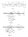
- a supply spool 12 is guided by a supply spool 12 via guide elements 13 to a take-up spool 14.
- the magnetic suspension 8 is applied to the film 1.
- the coated film still passes the straightening system 17 in the liquid state and then passes through a drying device 18.
- the suspension consists of a binder-containing lacquer with solvent and magnetic particles, such as iron oxides. Cr0 2 or metal powder. The solvent evaporates in the drying device so that the magnetic layer 11 is formed from the magnetic suspension.
- the particles of the suspension today almost exclusively have a pronounced magnetic preferred axis, which is based on the shape anisotropy and / or the crystal anisotropy. Elongated particles are preferably used.
- the straightening system creates a preferred axis of magnetization in the direction of the tape.
- a magnetizing coil through which the cast film is guided can be used as a straightening system. serve as in FR No. 1008218 and in the magazine Hochfrequenztechnik und Elektroakustik, April 1963, Vol. 72, No. 2, pages 54-63.
- Such a spool has the advantage of an extensive homogeneous field in the direction of tape travel, which can be adapted to the conditions specified by the suspension by changing the spool current.
- the major disadvantage of using a coil is that it has to be operated in a highly explosive atmosphere. This disadvantage has led to the fact that straightening systems which are constructed from permanent magnets are preferably used today.
- a frequently used and long-known system (US 2711 901) uses magnetic strips that face each other with poles of the same name.
- the film with the poured suspension is guided on the line of symmetry.
- the magnetic field acting on a pigment particle changes its direction by 180 ° during the passage of the particle. Because of this field course, good alignment is only achieved if the maximum amount of the directional field is significantly larger than the coercive field of the pigment particles.
- 2 of the patent shows the course of the longitudinal component of the directional field acting on the particles. The resulting cross field is zero.
- maximum field strengths of around 800 A / cm can be generated. This is sufficient to align pigments with coercive fields between 100 and 400 A / cm. With metal pigments with a coercive field strength of approximately 800 A / cm, alignment with such a system is unsatisfactory.
- DE-OS 2444971 describes a directional arrangement which allows several such systems to act in series. This is intended to correct a vertical field component that the directional magnet should have. This is preferably achieved in that the following pairs of the same-pole directional magnetic strips are of different geometries.
- the slit field of a magnetic circuit has also been proposed for generating a preferred magnetic direction in magnetic storage layers (GB 902838). What is crucial in this patent specification is the fact that the action of the gap field of the magnetic circuit on the movable magnetizable particles should rotate them from the gap field in the preferred direction in which the magnetization of the signal to be recorded should lie. It is irrelevant whether the gap field is generated by current or permanent magnets. No information is given about the strength of the gap field.
- the gap field of a magnetic circuit is also used for other purposes in magnetic tape production. For example, it serves to evenly distribute the suspension over the casting track (DE-OS 23 46 390) or to pull out the bead-like elevations at the edges (DE-OS 29 36 035). Both applications use the attraction, not the torque, of the magnetic field on the pigment particles, which is not important in the straightening process.
- DE-OS 23 46 390 S. 4 last paragraph it is expressly emphasized that it is not the task of alignment.
- DE-OS 2936035 the pigment is held in place by the slit field and by the movement of the film pressed outside. When straightening, however, it depends on the torque exerted by the field. Bate and Dunn in IEEE Trans.
- the following parameters are used in technology: velor effect, the ratio of remanence to saturation in the longitudinal direction of the strip M R / M s and the ratio of remanent magnetization in the longitudinal and transverse directions MR // / M R / .
- the velor effect is based on the fact that it is not always possible to orient the pigment particles in the tape running direction and parallel to the layer surface.
- the preferred magnetic axis is then inclined to this direction. Due to the inclined position of the preferred axis, a different remanent magnetization is achieved by the recording field with its approximately circular field line profile, depending on the direction in which the magnetic layer passes the recording field. This is because the angle between the field direction on the playing edge and the preferred axis for the two transport directions of the tape is different. This results in a different level, in particular when scanning short wavelengths (approximately 5 ⁇ m) for opposite recording directions.
- the velor effect is characterized by the logarithm of the ratio of the two levels:
- a value of V 2 dB means that the velor effect is strong.
- the values M R / M s or M R // MR / are used as a measure of the scatter of the preferred axes of the particles around the tape running direction.
- M R / M s the remanence M R and the saturation magnetization M s are measured in the direction of the preferred axis.
- the ratio M R / M s indicates the quality of the anisotropy. The closer the ratio approaches 1, the better the particles are oriented. Since the absolute saturation is never fully reached, the field control must be specified when comparing different samples.
- the MR / Ms value has the disadvantage that today it practically only varies between 0.7 and 0.96.
- M RI / M RL orientation ratio
- the object was achieved according to the invention by a magnet system for aligning the magnetic preferred axes of pigment particles of a magnetic and binder-containing dispersion applied to a layer support on casting machines, consisting of permanent magnets and soft magnetic elements for guiding the magnetic flux, the straightening system consisting of two subsystems, the Field of the first straightening system has a thickness between 1,600 and 16,000 A / cm and concentrates on a maximum cross section of 5 x 5 mm 2 , the field lines having a strongly curved course and a strong field gradient, and the field with the film lying against the gap leads to a main direction of the magnetization vectors of the particles, which is oriented obliquely to the tape running direction and the field of the subsequent second subsystem has a strength between 400 and 2400 A / cm and in the longitudinal direction an extension of at least 0.5 cm and essentially a longitudinal component te, which is oriented parallel to the film running direction and the magnets are arranged in mirror image to the film running direction, which are at a distance
- the first field magnetizes the pigment particles so that their magnetization vectors not deviate more than 90 ° from a main direction.
- a state corresponds to the remanent state of a previously saturated material.
- the main direction of the magnetization is not parallel to the layer surface and not parallel to the tape running direction due to the nature of the directional field, but has a component in the film running direction.
- the magnetization vectors of these particles can also be focused in the main direction by rotating the particles.
- the maximum magnetic field of the first alignment system must be at least twice as large as the coercive field of the pigment particles.
- the second part of this straightening system has the task of converting the magnetization vectors of the bundle into a position parallel to the tape running direction by mechanical rotation of the particles. This is achieved by the magnetic field acting in this second part of the straightening system, which has only one longitudinal component in the film running direction in the field region causing the indentation.
- the system is mirror-symmetrical to the film treadmill.
- the time that the particles are exposed to the field depends on the field expansion and the casting speed during the casting process. This time must be adapted to the time required to turn the particles in the direction of the film. Depending on the pigment type, paint type (viscosity) and field strength, this screwing-in time is between 0.01 and 0.1 seconds.
- the alignment quality is measured as a function of the film speed using one of the measurement methods specified above.
- the second part of the straightening system can be constructed from sections according to the subclaims, the length of the field of such a section should not drop below 0.5 cm in the longitudinal direction.
- the maximum field strength of the individual partial magnet systems should decrease monotonically with increasing distance from the caster. In particular, the maximum field strength of a partial magnet system should only be 20% of the maximum field strength of the previous system.
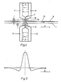
- FIG. 2 An example of the first part of the straightening system for generating a high inhomogeneous magnetic field is shown in cross section in FIG. 2. It consists of a strip-shaped permanent magnet 2 with a magnetic preferred axis 3, which is encompassed by two strip-shaped magnetic yokes 4/5. These yokes are made of a material with a saturation magnetization above 1.8 Tesla. They form a gap 5 which can be 30 f.l.m to 2 mm wide. Inhomogeneous fields 19 with a thickness of -5,000 A / cm are established across the gap. While the film 1 moves with the layer 8 in direct contact with the gap in the direction of arrow 9, the gap field 19 extends through the film onto the suspension.
- the edge of a strip-shaped cross-magnetized permanent magnet can also be used.
- Both known and inventive permanent magnet systems are used for the second part of the straightening system, which can be built up again from one or more subsystems.
- a system is shown in Fig. 4. It consists of two magnetic circuits, which are arranged in mirror image to the coated film (1, 8) and whose stray fields 19 act in the same direction.
- a single circle is constructed like the first part of the straightening system (FIG. 2).
- the gaps 6/7 of the second part of the straightening system are at a certain distance 20 from the film or the poured-on suspension.
- the distance 20 should be at least 3 mm. This distance results in a maximum longitudinal field of at least 800 A / cm in the middle of the arrangement.
- the required expansion of the field 19 of 2-3 cm in length is achieved by the curved surface 16 of the soft magnetic yokes 4/5.
- permanent magnetic materials such.
- 5 shows the field profile of the longitudinal components on the line of symmetry of such a magnet system that runs parallel to the film plane.
- the longitudinal component has a strong maximum in the middle of the system. To the right and left of this are small secondary maxima with opposite directions.
- the direction of the main maximum of the longitudinal component of the second part of the straightening system corresponds to the field direction on the line of symmetry of the gap of the first part of the straightening system.
- the amounts of the secondary maxima are considerably smaller than the amount of the main maximum, so that they can be neglected.
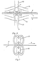
- FIG. 6 Another arrangement for the second part of the straightening system is shown in FIG. 6.
- a permanent magnetic plate 22 is cross-magnetized in the direction 3. It consists of magnetically anisotropic material with a high crystal anisotropy, which allows magnetization perpendicular to the surface. These surfaces then carry the magnetic load with positive and negative poles.
- the plate has a slot 23 of approximately 6 mm, through the middle of which the film 1 with the layer 8 runs.
- the course of the longitudinal components is qualitatively the same as in FIG. 5.
- the field lines 21 belong to the area which supplies the main maximum of the longitudinal component, while the field lines 24 show the development of the secondary maxima in the opposite direction.
- the systems shown in FIGS. 4 and 6 for implementing the second subsystem can also follow several times in succession, the field direction remaining unchanged at the main maximum.
- the system shown in FIG. 7, in which two poles of the same name face each other, can also be used as the second part of the straightening system. On its line of symmetry parallel to the film plane, it has two extreme values of the longitudinal component of the same magnitude with opposite signs.
- the advantage of this system is that the poles of the same name push the field out of the space between them, which results in an extended field area along the film. Even when the second subsystem is implemented by arranging the poles of the same name opposite, the second subsystem can be built up from a plurality of individual systems with poles of the same name opposite.
- This single system is used exclusively for the first part of the overall system. It is shown in cross section in Fig. 2.
- the cross section of the permanent magnet 2 was 3 x 24 mm, it was magnetized over the short edge.
- the outer dimensions of the yokes 4/5 are 14 x 40 mm 2 .
- the two-circuit system is shown in principle in Fig. 4. Ferrite rods with a cross section of 12 x 19 mm 2 were used as permanent magnets, which were magnetized along the short axis. The total width of the yokes was 24 mm. The gap width was 0.8 mm. Two systems with different field strengths were available.
- Characteristic of this system is the field profile shown in FIG. 5 with a strong field maximum in the middle and the two weak secondary maxima of opposite field directions on the edge.
- the alignment depends on the suspension used, in addition to the alignment system. Both the pigment and the lacquer have a decisive influence. The following two different suspensions were tested:
- the quality of the alignment is determined by the measurement variables MR / Ms; M R // / MR / . described.
- the field control for measuring the first two quantities was 3200 A / cm.
- Tables 1 and 2 below each show the alignment by one of the individual systems in the upper part and the results achieved with the combination according to the invention in the second part. (See tables on page 7 f.)
Landscapes
- Chemical & Material Sciences (AREA)
- Dispersion Chemistry (AREA)
- Manufacturing Of Magnetic Record Carriers (AREA)
- Hard Magnetic Materials (AREA)
Claims (10)
Applications Claiming Priority (2)
| Application Number | Priority Date | Filing Date | Title |
|---|---|---|---|
| DE3123746 | 1981-06-15 | ||
| DE19813123746 DE3123746A1 (de) | 1981-06-15 | 1981-06-15 | Magnetisches richtsystem |
Publications (3)
| Publication Number | Publication Date |
|---|---|
| EP0067367A2 EP0067367A2 (fr) | 1982-12-22 |
| EP0067367A3 EP0067367A3 (en) | 1984-08-29 |
| EP0067367B1 true EP0067367B1 (fr) | 1986-10-01 |
Family
ID=6134772
Family Applications (1)
| Application Number | Title | Priority Date | Filing Date |
|---|---|---|---|
| EP82104844A Expired EP0067367B1 (fr) | 1981-06-15 | 1982-06-03 | Système pour l'orientation magnétique |
Country Status (4)
| Country | Link |
|---|---|
| US (1) | US4440106A (fr) |
| EP (1) | EP0067367B1 (fr) |
| JP (1) | JPS581836A (fr) |
| DE (2) | DE3123746A1 (fr) |
Families Citing this family (12)
| Publication number | Priority date | Publication date | Assignee | Title |
|---|---|---|---|---|
| JPS60127527A (ja) * | 1983-12-15 | 1985-07-08 | Saiteku Kk | 膜状積重磁気記録媒体およびその製造方法 |
| CA1225358A (fr) * | 1984-03-28 | 1987-08-11 | Michael A. Shannon | Bobines pour la magnetisation d'un melange hydraulique magnetisable |
| DE3533968C2 (de) * | 1985-09-24 | 1995-06-08 | Weinsheim Chemie | Vorrichtung zur Magnetisierung von magnetisierbares Material enthaltenden Schichten |
| JPH069670B2 (ja) * | 1986-01-16 | 1994-02-09 | 富士写真フイルム株式会社 | 塗布方法 |
| JPH01184630A (ja) * | 1988-01-20 | 1989-07-24 | Internatl Business Mach Corp <Ibm> | 磁気粒子配向方法 |
| JPH042315U (fr) * | 1990-04-18 | 1992-01-09 | ||
| DE4130755A1 (de) * | 1991-09-16 | 1993-03-18 | Alois Hoerl | Vorrichtung zur behandlung durchgehend fluider, magnetsensibler systeme mit einem magnetfeld |
| US5378988A (en) * | 1993-01-22 | 1995-01-03 | Pulyer; Yuly M. | MRI system having high field strength open access magnet |
| RU2253910C2 (ru) * | 2002-07-02 | 2005-06-10 | Закрытое акционерное общество "Анна" | Устройство для стирания записи на магнитном носителе |
| US7986485B2 (en) * | 2009-03-31 | 2011-07-26 | Oracle America, Inc. | Servo writer providing a pre-writing, longitudinal magnetic bias in a magnetically unoriented tape supply |
| JP5929962B2 (ja) * | 2014-05-16 | 2016-06-08 | トヨタ自動車株式会社 | 付勢部材の取付構造 |
| CN115762943A (zh) * | 2022-12-23 | 2023-03-07 | 东莞金坤新材料股份有限公司 | 一种定向磁力式钕铁硼磁铁的制造方法 |
Family Cites Families (14)
| Publication number | Priority date | Publication date | Assignee | Title |
|---|---|---|---|---|
| US2711901A (en) * | 1952-05-21 | 1955-06-28 | Minnesota Mining & Mfg | Magnetic recording tape and method of making same |
| US2796359A (en) * | 1952-07-05 | 1957-06-18 | Audio Devices Inc | Production of magnetic sound recording tape |
| US2711359A (en) * | 1953-10-19 | 1955-06-21 | Kamyr Ab | Bleaching plant and method of bleaching cellulose pulp |
| FR1181257A (fr) * | 1956-08-18 | 1959-06-12 | Philips Nv | Porte-magnétogramme |
| BE582785A (fr) * | 1958-09-19 | 1960-03-18 | Agfa Ag | Procédé de production d'enregistrements magnétiques pour enregistrer des signaux dans des directions spatialement différentes |
| US3021230A (en) * | 1959-04-17 | 1962-02-13 | Eastman Kodak Co | Apparatus and method for magnetically orienting particles |
| US3117065A (en) * | 1959-09-02 | 1964-01-07 | Magnetic Film And Tape Company | Method and apparatus for making magnetic recording tape |
| GB996606A (en) * | 1960-11-15 | 1965-06-30 | Ibm | Method of preparing a magnetic record member |
| DE1295732B (de) * | 1962-08-24 | 1969-05-22 | Gevaert Photo Prod Nv | Vorrichtung zur Herstellung eines bandfoermigen Magnetogrammtraegers |
| DE1202333B (de) * | 1964-07-21 | 1965-10-07 | Basf Ag | Verfahren zur Herstellung von bandfoermigen Magnetogrammtraegern fuer die Aufzeichnung und Abtastung von Signalen in mehreren benachbarten Spuren unter verschiedenen Winkeln |
| FR1587568A (fr) * | 1968-10-25 | 1970-03-20 | ||
| DE2444971A1 (de) * | 1974-09-20 | 1976-04-01 | Bayer Ag | Vorrichtung zur herstellung von magnetbaendern mit verbesserter ausrichtung |
| US4177442A (en) * | 1975-08-29 | 1979-12-04 | International Business Machines Corporation | Production of magnetic media |
| DE2936035C2 (de) * | 1979-09-06 | 1981-09-24 | Agfa-Gevaert Ag, 5090 Leverkusen | Verfahren zum Auftragen von magnetischen, bindemittelhaltigen Dispersionen auf flexible Schichtträger |
-
1981
- 1981-06-15 DE DE19813123746 patent/DE3123746A1/de not_active Withdrawn
-
1982
- 1982-06-03 EP EP82104844A patent/EP0067367B1/fr not_active Expired
- 1982-06-03 DE DE8282104844T patent/DE3273535D1/de not_active Expired
- 1982-06-08 US US06/386,400 patent/US4440106A/en not_active Expired - Fee Related
- 1982-06-11 JP JP57099462A patent/JPS581836A/ja active Granted
Also Published As
| Publication number | Publication date |
|---|---|
| JPH0328734B2 (fr) | 1991-04-22 |
| EP0067367A3 (en) | 1984-08-29 |
| EP0067367A2 (fr) | 1982-12-22 |
| DE3273535D1 (en) | 1986-11-06 |
| DE3123746A1 (de) | 1982-12-30 |
| US4440106A (en) | 1984-04-03 |
| JPS581836A (ja) | 1983-01-07 |
Similar Documents
| Publication | Publication Date | Title |
|---|---|---|
| DE2559649C2 (de) | Dauermagnetische Haltevorrichtung | |
| EP0067367B1 (fr) | Système pour l'orientation magnétique | |
| DE3525383A1 (de) | Verfahren und vorrichtung zum entmagnetisieren magnetischer aufzeichnungsmedien | |
| EP0135738B1 (fr) | Tête magnétique de lecture et d'écriture pour support d'enregistrement à magnétisation verticale | |
| DE2257029C3 (de) | Einrichtung zum Magnetisieren und Abtasten magnetisierbarer Bereiche auf einem Aufzeichnungsträger | |
| DE2440920A1 (de) | Anordnung zur herstellung eines magnetischen aufzeichnungstraegers mit magnetischer vorzugsrichtung | |
| EP0121093A2 (fr) | Procédé pour la fabrication d'un matériau avec orientation perpendiculaire pour l'enregistrement magnétique | |
| EP0025095B1 (fr) | Dispositif pour la séparation magnétique à gradient élevé | |
| EP0037467B1 (fr) | Dispositif d'aimantation pour l'engendrement d'une orientation préférentielle dans des supports d'enregistrement magnétique | |
| DE4011694A1 (de) | Magnetische aufzeichnungsvorrichtung | |
| DE2658956A1 (de) | Vertikales magnetisches informationsaufzeichnungssystem | |
| DE102020116096A1 (de) | Vorrichtung und Verfahren zum Erzeugen eines inhomogenen Magnetfeldes | |
| DE2446879A1 (de) | Magnetloeschkopf | |
| DE69230389T2 (de) | Magnetaufzeichnungskopf geeignet zur Definierung von schmaler Spurbreite und Magnetaufzeichnungsgerät für dessen Verwendung | |
| DE2839046C2 (fr) | ||
| EP0144601A1 (fr) | Tête de lecture pour l'exploration magnétique de fils Wiegand | |
| DE3046515C2 (fr) | ||
| DE1279743B (de) | Zerstoerungsfrei ablesbare Speichervorrichtung und Verfahren zu ihrer Ansteuerung | |
| DE2641578A1 (de) | Magnetisches aufzeichnungsmedium mit zwei teilchenarten | |
| DE3736024C1 (en) | Demagnetising device | |
| DE69614727T2 (de) | Magnetisches Aufzeichnungsmedium und Verfahren zur Herstellung desselben | |
| DE3330077A1 (de) | Einrichtung zum herauslesen von informationen, die nach dem prinzip der senkrechten magnetisierung in einem aufzeichnungsmedium eingespeichert sind | |
| DE69908392T2 (de) | Fernfeldmagnetresensibilisierungsapparat für warenüberwachungssysteme | |
| DE19516474C2 (de) | Verfahren und Vorrichtung zur Herstellung von magnetischen Aufzeichnungsmedien | |
| DE3806171A1 (de) | Duennfilm-magnetkopf mit schichtweisem aufbau zur longitudinalen magnetisierung |
Legal Events
| Date | Code | Title | Description |
|---|---|---|---|
| PUAI | Public reference made under article 153(3) epc to a published international application that has entered the european phase |
Free format text: ORIGINAL CODE: 0009012 |
|
| 17P | Request for examination filed |
Effective date: 19820603 |
|
| AK | Designated contracting states |
Designated state(s): DE FR GB IT NL |
|
| PUAL | Search report despatched |
Free format text: ORIGINAL CODE: 0009013 |
|
| AK | Designated contracting states |
Designated state(s): DE FR GB IT NL |
|
| GRAA | (expected) grant |
Free format text: ORIGINAL CODE: 0009210 |
|
| ITF | It: translation for a ep patent filed | ||
| AK | Designated contracting states |
Kind code of ref document: B1 Designated state(s): DE FR GB IT NL |
|
| REF | Corresponds to: |
Ref document number: 3273535 Country of ref document: DE Date of ref document: 19861106 |
|
| ET | Fr: translation filed | ||
| RAP2 | Party data changed (patent owner data changed or rights of a patent transferred) |
Owner name: AGFA-GEVAERT AG |
|
| PLBE | No opposition filed within time limit |
Free format text: ORIGINAL CODE: 0009261 |
|
| STAA | Information on the status of an ep patent application or granted ep patent |
Free format text: STATUS: NO OPPOSITION FILED WITHIN TIME LIMIT |
|
| 26N | No opposition filed | ||
| GBPC | Gb: european patent ceased through non-payment of renewal fee | ||
| REG | Reference to a national code |
Ref country code: GB Ref legal event code: 746 |
|
| ITPR | It: changes in ownership of a european patent |
Owner name: OFFERTA DI LICENZA AL PUBBLICO |
|
| ITTA | It: last paid annual fee | ||
| ITPR | It: changes in ownership of a european patent |
Owner name: CESSIONE;BASF MAGNETICS GMBH |
|
| NLS | Nl: assignments of ep-patents |
Owner name: BASF MAGNETICS GMBH TE MANNHEIM, BONDSREPUBLIEK DU |
|
| REG | Reference to a national code |
Ref country code: FR Ref legal event code: TP |
|
| REG | Reference to a national code |
Ref country code: GB Ref legal event code: 732 |
|
| PGFP | Annual fee paid to national office [announced via postgrant information from national office to epo] |
Ref country code: NL Payment date: 19920630 Year of fee payment: 11 |
|
| PG25 | Lapsed in a contracting state [announced via postgrant information from national office to epo] |
Ref country code: NL Effective date: 19940101 |
|
| NLV4 | Nl: lapsed or anulled due to non-payment of the annual fee | ||
| PGFP | Annual fee paid to national office [announced via postgrant information from national office to epo] |
Ref country code: FR Payment date: 19940525 Year of fee payment: 13 |
|
| PGFP | Annual fee paid to national office [announced via postgrant information from national office to epo] |
Ref country code: GB Payment date: 19940601 Year of fee payment: 13 |
|
| PGFP | Annual fee paid to national office [announced via postgrant information from national office to epo] |
Ref country code: DE Payment date: 19940624 Year of fee payment: 13 |
|
| PG25 | Lapsed in a contracting state [announced via postgrant information from national office to epo] |
Ref country code: GB Effective date: 19950603 |
|
| GBPC | Gb: european patent ceased through non-payment of renewal fee |
Effective date: 19950603 |
|
| PG25 | Lapsed in a contracting state [announced via postgrant information from national office to epo] |
Ref country code: FR Effective date: 19960229 |
|
| PG25 | Lapsed in a contracting state [announced via postgrant information from national office to epo] |
Ref country code: DE Effective date: 19960301 |
|
| REG | Reference to a national code |
Ref country code: FR Ref legal event code: ST |