EP0121093A2 - Procédé pour la fabrication d'un matériau avec orientation perpendiculaire pour l'enregistrement magnétique - Google Patents
Procédé pour la fabrication d'un matériau avec orientation perpendiculaire pour l'enregistrement magnétique Download PDFInfo
- Publication number
- EP0121093A2 EP0121093A2 EP84102048A EP84102048A EP0121093A2 EP 0121093 A2 EP0121093 A2 EP 0121093A2 EP 84102048 A EP84102048 A EP 84102048A EP 84102048 A EP84102048 A EP 84102048A EP 0121093 A2 EP0121093 A2 EP 0121093A2
- Authority
- EP
- European Patent Office
- Prior art keywords
- layer
- magnetic
- field
- pigments
- normal
- Prior art date
- Legal status (The legal status is an assumption and is not a legal conclusion. Google has not performed a legal analysis and makes no representation as to the accuracy of the status listed.)
- Granted
Links
Images
Classifications
-
- G—PHYSICS
- G11—INFORMATION STORAGE
- G11B—INFORMATION STORAGE BASED ON RELATIVE MOVEMENT BETWEEN RECORD CARRIER AND TRANSDUCER
- G11B5/00—Recording by magnetisation or demagnetisation of a record carrier; Reproducing by magnetic means; Record carriers therefor
- G11B5/84—Processes or apparatus specially adapted for manufacturing record carriers
- G11B5/842—Coating a support with a liquid magnetic dispersion
- G11B5/845—Coating a support with a liquid magnetic dispersion in a magnetic field
Definitions
- the invention relates to a method for producing a magnetic recording material with at least one layer consisting of magnetic pigments embedded in binder, the recording material having a magnetic preferred axis perpendicular to the layer surface or a layer structure derived therefrom in terms of process.
- the first magnetic recording materials of technical importance which were known from binders with embedded magnetic pigments, were magnetically isotropic layers. Cubic iron oxide particles dispersed in a binder were applied to a base with a caster. The casting device contained no magnetic elements.
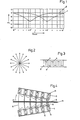
- FIG. 1 shows the dependence of the remanent band flux on the wavelength reproduced in the cited article for an oxidic (---- 1) and a metallic (-2) storage layer.
- the hysteresis loop of the force flow of both layers was assumed to be the same.
- the layer thickness of the metal strip (d M ) is therefore only about 1 of the thickness of the oxide strip (d 0 ).
- An isotropic magnetic layer is magnetized longitudinally at long wavelengths ( ⁇ ) at which ⁇ > d (d - layer thickness), since this state is the more energetically favorable because of the demagnetizing field.
- ⁇ the wavelength at which ⁇ > d (d - layer thickness)
- d the wavelength at which ⁇ > d (d - layer thickness)
- the ratio d: ⁇ increases and, because of the shear of the hysteresis loop, the remanent magnetization decreases.
- the direction perpendicular to the strip surface begins to have equal rights and becomes more energetically more favorable as the wavelength drops further, so that the magnetization is preferably in the normal direction.
- the retentive river 0 ⁇ now rises again.
- the wavelength is based on the layer thickness of a metal strip d M (about 0.3 ⁇ m).
- metal layers have a magnetic preferred axis in the direction of the surface normal of the recording material.
- the technology of metal layer production is only now emerging, while the technology of oxide layer production is generally highly perfected.
- the obvious idea of aligning the preferred axis of the magnetic pigments by means of a constant field, which acts on the still liquid pigment dispersion during the production process, is specified in DE-OS 31 48 769 for pigments with an aspect ratio of less than 3: 1.
- the limitation shows that the process still has significant shortcomings. Brings disadvantages in particular of the applied temperature drop to solidify the liquid dispersion, since Darun - ter the homogeneity of the coating suffers. It is equally unfavorable that the direct field directed perpendicular to the still liquid storage layer creates an extremely strong demagnetizing field against the direct field in the layer. This weakens the effective field and makes vertical orientation difficult.
- DE-OS 32 17 211 describes a further method for generating a magnetic anisotropy perpendicular to the layer surface.
- the magnetic pigment is subjected to heat treatment in the magnetic field.
- the powder can be exposed to this thermomagnetic treatment before or after it is applied in the same field to the substrate.
- This patent also has the defect that when the pigments are aligned in the same field, this is counteracted by a high demagnetizing field.
- the thermomagnetic treatment is carried out on the pigments located on the film, high demands must be placed on the thermal stability of the layer support. Another disadvantage is the high expenditure of time that is required for the thermomagnetic method.
- the invention is therefore the object of a method for producing a magnetic recording material with at least one layer of magnetic oxidic and / or metallic acicular pigments with shape anisotropy and / or another type of magnetic anisotropy z.
- the following structures should be realized with the method.
- the object is achieved according to the invention by a method for producing a magnetic recording material having at least one layer of magnetically anisotropic pigments which are dispersed in a binder, the magnetic dispersion being subjected to an external magnetic field in the liquid suspension state after application to the layer support, which acts essentially parallel to the layer normal, whereby the field orientation in the casting direction changes continuously by 180 0 while the field strength decreases, so that the pigments turn with their preferred axis into the normal axis of the layer and, due to the demagnetization or deletion effect, spatially small areas with form reduced stray field energy and the pigments are then fixed by drying.
- the demagnetization energy of the storage layer is thus significantly reduced.
- 3 shows such small areas with changing magnetization direction 11 and the partition walls 17.
- the drying point is placed at the point at which the wet layer enters the magnet arrangement, so that a spatially isotropic distribution of the preferred axes of the particles is achieved, that only a part of the preferred axes is more or less screwed into the layer normal.
- the drying point is placed at the point at which the wet layer leaves the magnet arrangement according to the invention.
- the drying and fixing point lies far away from the alignment arrangement.
- the wet layer passes through the arrangement according to the invention for aligning the particles in the normal direction of the layer.
- the particles then fall over like the micro sticks and are statistically distributed parallel to the layer surface.
- the method is not restricted to any specific magnetic material of the pigments. It applies, for example, to all magnetic pigments known today, such as Fe 3 0 4 , r-Fe 2 0 3 , Berthollide, Cr0 2 , metal powder, barium ferrite, rare earth magnet.
- the magnetic layer is composed of binders, solvents and other additives such as dispersants, lubricants, wetting agents.
- binders such as polyvinyl compounds, polyesters, polyurethanes, cellulose derivatives and the like are used as binders.
- flexible and rigid materials such as PET, polyolefins, cellulose derivatives, non-magnetic metals such as aluminum or ceramic materials such as glass are used as layer supports.
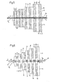
- FIG. 1 The arrangement consists of two identical chains of magnets (15), which are to be referred to as magnetic carpets (3, 4). These magnetic carpets lie symmetrically to the film (5) with the still liquid layer (6) on it. With arrow (7) is the movement marked in the direction of the film.
- the north (N) and south poles (S) of the carpets (3, 4) always face each other, so that perpendicular to the film (5) and layer (6), i.e. the line of symmetry, magnetic fields (8) are created, which are their direction change alternately.
- the strength of the fields decreases on the line of symmetry, in the direction (7) in which the still liquid layer moves through the magnet arrangement.
- the field (8) used for alignment and demagnetization decreases monotonously as possible.
- One way to do this is to consider manufacturing accuracy as a design focus.
- the many required individual parts of the many individual circles are manufactured in the same dimensions and magnetic values.
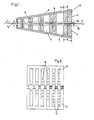
- the decrease in the field on the line of symmetry is then achieved by allowing the two identical magnetic circuit arrangements to wedge apart, as shown in FIG. 4.
- a low longitudinal component is required, which can be achieved by slightly shifting the two magnetic carpets (3, 4) in the running direction (7) or by guiding the layer carrier slightly outside the line of symmetry between the two pole chains.
- FIGS. 5-7 Another possibility is to focus on an optimal field geometry of the entire straightening and demagnetization path. Examples of this are given in FIGS. 5-7.
- One of the principles of forming an optimal field geometry is that the field strength H E is designed to be as high as possible at the entrance of the layer (6) into the magnetic carpet arrangement (3, 4).
- the distance ⁇ E of the two magnetic carpets (3, 4) is always chosen to be as small as possible at the entrance.
- the mechanical guidance and the paint behavior limit the distance downwards.
- the pole width can be chosen somewhat larger at the entrance in favor of increasing the field strength (FIGS. 5, 7).
- the distance between the poles of a chain ( ) should be dimensioned as small as possible (FIGS. 5, 7), so that magnetic areas that are as spatially small as possible are formed in the layer.
- the stray field of the overall arrangement of the magnetic carpets (3, 4) does not interfere with the monotonously periodic decrease in the erase field upon exiting the layer (6) (g Fi. 5, 6, 7, 10), that is, the Starting point of the field lines of the total stray field of the arrangement is distributed over the entire length of the magnetic carpets (3, 4).
- the distance (a) between the two magnetic carpets (3, 4) should be as small and constant as possible from start to finish (1 - 3 mm).
- the magnetic energy provided by the magnets should decrease from the beginning to the end, i. H. the magnet volume should always get smaller.
- the magnetic circuits can be built up from bar and / or block magnets.
- the highly coercive magnetic materials with a high energy product such as barium ferrite and rare earth magnets, are preferred.
- the barium ferrite block magnets (16) (Fig. are often magnetized along the short form axis (arrows 18) and combined with soft magnetic material (9) with high saturation magnetization.
- Fig. 6 shows an example in which the decrease in the field (8) is achieved by shortening the contact surface between the hard and soft magnetic material.
- the dimensions b and - / L / 2 can also be reduced in the running direction of the storage layer.
- FIG. 7 shows a sketch.
- the bar magnets 15 made of CoSm have the magnetic preferred axis 18 perpendicular to the layer 6. Their volume (depth and length) decreases in the direction of the arrow (7).
- a soft magnetic flux conductor (9) serves to reduce the demagnetization factor of the individual magnetic circuits.
- Non-magnetic filling material (10) is attached between the magnets 15.
- electromagnetic systems they must usually be externally ventilated with a high level of technical effort in order to avoid explosions.
- the design and manufacture of the electromagnetic systems are based on that of electric motors, especially linear motors.
- electric motors especially linear motors.
- One method to change the current in the individual grooves and thus the field can be that between the teeth of the combs, electrical resistors are connected in parallel to the turns.
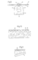
- the number of current-carrying wires (12) can also be changed, as shown in FIG. 8.
- the uprighting of the particles or the approximation to the vertical position of the particles can be achieved (FIG. 9) by directly covering the film (5) covered with the liquid layer 6 via a 0.1 to 1 mm wide gap (13) like netic circle 14 of permanent magnets 16 and soft magnetic flux conductor parts 9 leads. From the indicated course of the magnetic field (8) it can be seen that the layer (6) in the outlet is essentially subjected to a magnetic field perpendicular to the tape surface.
- an air flow adjustable in temperature and wind speed is blown against the direction of travel to solidify the dispersion on the substrate.
- the air flow can also be diverted perpendicular to the direction of flow in the middle third of an alternating field magnet arrangement, so that the pigments are still highly mobile in the first third, and the layer is intensified in the last third.
- the air flow can also be blown parallel to the layer plane, but perpendicular to the direction of travel. The person skilled in the art can test which method is the cheapest for each individual case.
- a modern means is the use of Peltier elements, with which different points of the magnet arrangement can be heated or cooled.
- UV radiation ultraviolet radiation, infrared radiation
- the film through the magnet arrangement can be done by rolling or baffles.
- the principle of levitation can also be used.
- the external demagnetization factor can usually be set to zero by means of a suitable sample shape, since the layer extension is greater than the layer thickness.
- the measurement in the normal direction is very difficult.
- the measuring field must magnetize the sample perpendicular to the layer surface, so that a very large demagnetizing field is created.
- the demagnetization factor is 1 or 4 ⁇ depending on the measurement system. Due to the high demagnetizing field, very high fields (greater than 10,000 ( can be used for magnetizing. Due to this fact, a vibration magnetometer in combination with a Weiss magneton has proven itself well.
- the alignment can be determined using X-ray images.
- the advantage of volume detection is here.
- test samples with longitudinal pigment particles can be produced by a suitable magnet system during the casting process. This technique is well known.
- Type (Fig. 10) magnetic carpet system made of the same individual parts.
- the two magnetic carpets (3, 4) consist of the same magnetic circuits strung together.
- the fields acting on the layer are removed by tilting the magnetic carpets (3, 4).
- the individual magnetic circles consist of block-shaped barium ferrite magnets 16 measuring 3 x 21 x 50 mm, which are magnetized over the shortest edge. Such magnets provide z.
- B. the stainless steel works Dortmund under the material designation 300 K. Rectangular rails made of soft magnetic conductive material 9 with the dimensions 3 x 25 x 200 flank the Barrium ferrite stones, which are arranged in the brick wall composite.
- the free space 10 is filled with non-magnetic filling material. A sequence of 50 north and south poles (N, S) was used.
- the entrance opening between the magnets is 1.5 mm to 2.0 mm.
- the opening angle can be changed to optimize the manufacturing conditions.
- the outlet opening can therefore be set between 1.5 mm and 18 mm.
- the maximum field strength at the entrance to the arrangement was 1,000-1,100 Oe.
- FIG. 11 2nd type (Fig. 11) with dissimilar CoSm magnets and soft magnetic backing.
- This type of magnetic carpet is shown in principle in FIG. 5.
- the non-magnetic material between the "bar magnets” (15) could be dispensed with, since CoSm has a sufficiently strong anisotropy.
- These bar magnets about 3 mm wide, were placed on a soft magnetic flux conductor 9, 5 mm thick, in order to depress the demagnetization factor of the circles.
- the bar magnets initially had a length of 10 mm, which dropped to zero over a length of about 30 cm.
- the magnetic usable surfaces were spaced about 2 - 3 mm apart. But they could also be tilted against each other.
- the additional magnets placed in front of the magnetic carpets (3, 4) have the task of facilitating the vertical position.
- the pigment particles are aligned longitudinally with two strips, whose poles of the same name face each other.
- the maximum field in the tape running direction was 1 100 Oe.
- the split strips, which are used to prepare the vertical position, are in principle shown in Fig. 9.
- the block-shaped permanent magnet 16 had a cross section of 3 x 23 mm and was made of barium ferrite (300 K).
- the soft magnetic yoke 9 had an overall height of 23 mm and an overall width of 10 mm.
- the gaps between the two magnets in series were 0.4 and 0.8 mm.
Landscapes
- Chemical & Material Sciences (AREA)
- Dispersion Chemistry (AREA)
- Magnetic Record Carriers (AREA)
- Manufacturing Of Magnetic Record Carriers (AREA)
- Paints Or Removers (AREA)
Applications Claiming Priority (2)
| Application Number | Priority Date | Filing Date | Title |
|---|---|---|---|
| DE3308052 | 1983-03-08 | ||
| DE19833308052 DE3308052A1 (de) | 1983-03-08 | 1983-03-08 | Verfahren zur herstellung eines magnetischen aufzeichnungsmaterials mit senkrechtausrichtung |
Publications (3)
| Publication Number | Publication Date |
|---|---|
| EP0121093A2 true EP0121093A2 (fr) | 1984-10-10 |
| EP0121093A3 EP0121093A3 (en) | 1986-01-08 |
| EP0121093B1 EP0121093B1 (fr) | 1988-12-07 |
Family
ID=6192756
Family Applications (1)
| Application Number | Title | Priority Date | Filing Date |
|---|---|---|---|
| EP84102048A Expired EP0121093B1 (fr) | 1983-03-08 | 1984-02-28 | Procédé pour la fabrication d'un matériau avec orientation perpendiculaire pour l'enregistrement magnétique |
Country Status (4)
| Country | Link |
|---|---|
| US (1) | US4578280A (fr) |
| EP (1) | EP0121093B1 (fr) |
| JP (1) | JPS59168938A (fr) |
| DE (2) | DE3308052A1 (fr) |
Cited By (1)
| Publication number | Priority date | Publication date | Assignee | Title |
|---|---|---|---|---|
| EP0469431A1 (fr) * | 1990-08-01 | 1992-02-05 | BASF Magnetics GmbH | Dispositif pour effacer des milieux d'enregistrement magnétiques |
Families Citing this family (15)
| Publication number | Priority date | Publication date | Assignee | Title |
|---|---|---|---|---|
| JPS60127527A (ja) * | 1983-12-15 | 1985-07-08 | Saiteku Kk | 膜状積重磁気記録媒体およびその製造方法 |
| DE3683397D1 (de) * | 1985-05-20 | 1992-02-27 | Fujitsu Ltd | Aufzeichnungsmedium mit longitudinal ausgerichteter magnetischer schicht. |
| DE3533968C2 (de) * | 1985-09-24 | 1995-06-08 | Weinsheim Chemie | Vorrichtung zur Magnetisierung von magnetisierbares Material enthaltenden Schichten |
| US4824708A (en) * | 1985-11-11 | 1989-04-25 | Canon Kabushiki Kaisha | Process for producing magnetic recording medium |
| DE3541293A1 (de) * | 1985-11-22 | 1987-05-27 | Joachim Dr Greiner | Loeschverfahren fuer magnetische, bewegte, flaechige informationsspeicher |
| US4867101A (en) * | 1986-07-10 | 1989-09-19 | Fuji Photo Film Co., Ltd. | Apparatus for producing magnetic recording medium |
| US4778719A (en) * | 1986-08-25 | 1988-10-18 | Eastman Kodak Company | Particulate magnetic recording media and method of manufacture thereof |
| US4865703A (en) * | 1986-08-25 | 1989-09-12 | Eastman Kodak Company | Particulate magnetic recording media and method of manufacture thereof |
| US4805065A (en) * | 1986-10-29 | 1989-02-14 | Eastman Kodak Company | Particulate magnetic recording media having an areally controlled recording characteristics |
| JPH0766527B2 (ja) * | 1987-03-28 | 1995-07-19 | 富士写真フイルム株式会社 | 磁気記録媒体とその製造方法 |
| US4859495A (en) * | 1988-03-15 | 1989-08-22 | Eastman Kodak Co. | Method of preparing perpendicularly oriented magnetic recording media |
| US5336559A (en) * | 1988-12-28 | 1994-08-09 | Konica Corporation | Magnetic recording medium |
| US5230818A (en) | 1991-12-20 | 1993-07-27 | Eastman Kodak Company | Coating compositions for master media for anhysteretic recording |
| DE19747068A1 (de) | 1997-10-24 | 1999-04-29 | Emtec Magnetics Gmbh | Magnetischer Aufzeichnungsträger mit hoher Aufzeichnungsdichte und Verfahren zu seiner Herstellung |
| JP4684263B2 (ja) * | 2007-06-18 | 2011-05-18 | 日立マクセル株式会社 | 磁気記録媒体の消磁装置及び消磁方法と磁気記録媒体の製造方法 |
Family Cites Families (15)
| Publication number | Priority date | Publication date | Assignee | Title |
|---|---|---|---|---|
| US3172776A (en) * | 1965-03-09 | Process of making magnetic tape | ||
| US3131078A (en) * | 1958-05-21 | 1964-04-28 | Lab For Electronics Inc | Random storage |
| US3001891A (en) * | 1959-06-30 | 1961-09-26 | Rca Corp | Method and apparatus for preparing magnetic recording elements |
| US3627580A (en) * | 1969-02-24 | 1971-12-14 | Eastman Kodak Co | Manufacture of magnetically sensitized webs |
| DE2161083A1 (de) * | 1971-12-09 | 1973-06-14 | Basf Ag | Verfahren und vorrichtung zur herstellung bandfoermiger magnetogrammtraeger |
| JPS549905A (en) * | 1977-06-24 | 1979-01-25 | Fujitsu Ltd | Production of magnetic discs |
| JPS5411704A (en) * | 1977-06-28 | 1979-01-29 | Fujitsu Ltd | Production of magnetic discs |
| US4208447A (en) * | 1978-06-05 | 1980-06-17 | International Business Machines Corporation | Method for disorienting magnetic particles |
| US4271782A (en) * | 1978-06-05 | 1981-06-09 | International Business Machines Corporation | Apparatus for disorienting magnetic particles |
| JPS56105341A (en) * | 1980-01-28 | 1981-08-21 | Tdk Corp | Production of magnetic recording medium |
| JPS56119938A (en) * | 1980-02-22 | 1981-09-19 | Sony Corp | Production of magnetic recording medium |
| JPS57154656A (en) * | 1981-03-19 | 1982-09-24 | Hitachi Maxell Ltd | Production of magnetic recording medium |
| JPS57183630A (en) * | 1981-05-07 | 1982-11-12 | Fuji Photo Film Co Ltd | Magnetic recording medium |
| JPS59124039A (ja) * | 1982-12-29 | 1984-07-18 | Fuji Photo Film Co Ltd | 磁気記録媒体の製法 |
| JPS59148140A (ja) * | 1983-02-14 | 1984-08-24 | Fuji Photo Film Co Ltd | 磁気記録媒体の製造法 |
-
1983
- 1983-03-08 DE DE19833308052 patent/DE3308052A1/de not_active Withdrawn
-
1984
- 1984-02-27 US US06/583,727 patent/US4578280A/en not_active Expired - Fee Related
- 1984-02-28 EP EP84102048A patent/EP0121093B1/fr not_active Expired
- 1984-02-28 DE DE8484102048T patent/DE3475579D1/de not_active Expired
- 1984-03-07 JP JP59042219A patent/JPS59168938A/ja active Granted
Cited By (1)
| Publication number | Priority date | Publication date | Assignee | Title |
|---|---|---|---|---|
| EP0469431A1 (fr) * | 1990-08-01 | 1992-02-05 | BASF Magnetics GmbH | Dispositif pour effacer des milieux d'enregistrement magnétiques |
Also Published As
| Publication number | Publication date |
|---|---|
| DE3308052A1 (de) | 1984-09-13 |
| JPH0570208B2 (fr) | 1993-10-04 |
| DE3475579D1 (en) | 1989-01-12 |
| JPS59168938A (ja) | 1984-09-22 |
| EP0121093A3 (en) | 1986-01-08 |
| US4578280A (en) | 1986-03-25 |
| EP0121093B1 (fr) | 1988-12-07 |
Similar Documents
| Publication | Publication Date | Title |
|---|---|---|
| EP0121093B1 (fr) | Procédé pour la fabrication d'un matériau avec orientation perpendiculaire pour l'enregistrement magnétique | |
| DE3219779C3 (de) | Magnetaufzeichnungsmaterial | |
| DE2451796C2 (de) | Magnetischer Aufzeichnungsträger | |
| DE2827429A1 (de) | Magnetische duennfilmstruktur mit ferro- und antiferromagnetischem austausch- vorspannungsfilm | |
| DE3885335T2 (de) | Scheibenförmiges Magnetpulver und dessen Herstellungsverfahren sowie ein Aufnahmemedium aus diesem Magnetpulver. | |
| EP0290811B1 (fr) | Dispositif pour la mesure de l'intensité et de la direction d'un champs magnétique, en particulier du champ géomagnétique | |
| DE3525383A1 (de) | Verfahren und vorrichtung zum entmagnetisieren magnetischer aufzeichnungsmedien | |
| DE2440920A1 (de) | Anordnung zur herstellung eines magnetischen aufzeichnungstraegers mit magnetischer vorzugsrichtung | |
| EP0025095B1 (fr) | Dispositif pour la séparation magnétique à gradient élevé | |
| EP0067367B1 (fr) | Système pour l'orientation magnétique | |
| DE2161083A1 (de) | Verfahren und vorrichtung zur herstellung bandfoermiger magnetogrammtraeger | |
| DE2638133C2 (de) | Stufenlos regelbare verschleißfreie dauermagnetische Wirbelstrom- und/oder Hysteresebremse, vorzugsweise für Schienenfahrzeuge | |
| DE1267251B (de) | Magnetische Kodierscheibe und Verfahren zu ihrer Herstellung | |
| DE3219778A1 (de) | Magnetisches aufzeichnungsmaterial | |
| DE2658956A1 (de) | Vertikales magnetisches informationsaufzeichnungssystem | |
| DE69230389T2 (de) | Magnetaufzeichnungskopf geeignet zur Definierung von schmaler Spurbreite und Magnetaufzeichnungsgerät für dessen Verwendung | |
| DE2641578A1 (de) | Magnetisches aufzeichnungsmedium mit zwei teilchenarten | |
| DE3736024C1 (en) | Demagnetising device | |
| DE2261450A1 (de) | Loescheinrichtung fuer bewegte magnetische aufzeichnungstraeger | |
| DE2642950A1 (de) | Anordnung zum lesen von magnetisierungsmustern | |
| DE3541293C2 (fr) | ||
| DE60010132T2 (de) | Verfahren zur Herstellung eines biegsamen Magnetbandes | |
| DE69908392T2 (de) | Fernfeldmagnetresensibilisierungsapparat für warenüberwachungssysteme | |
| DE19516474C2 (de) | Verfahren und Vorrichtung zur Herstellung von magnetischen Aufzeichnungsmedien | |
| DE3544851C2 (fr) |
Legal Events
| Date | Code | Title | Description |
|---|---|---|---|
| PUAI | Public reference made under article 153(3) epc to a published international application that has entered the european phase |
Free format text: ORIGINAL CODE: 0009012 |
|
| 17P | Request for examination filed |
Effective date: 19840228 |
|
| AK | Designated contracting states |
Designated state(s): DE FR GB NL |
|
| PUAL | Search report despatched |
Free format text: ORIGINAL CODE: 0009013 |
|
| AK | Designated contracting states |
Designated state(s): DE FR GB NL |
|
| RAP1 | Party data changed (applicant data changed or rights of an application transferred) |
Owner name: AGFA-GEVAERT AG |
|
| 17Q | First examination report despatched |
Effective date: 19870316 |
|
| GRAA | (expected) grant |
Free format text: ORIGINAL CODE: 0009210 |
|
| AK | Designated contracting states |
Kind code of ref document: B1 Designated state(s): DE FR GB NL |
|
| REF | Corresponds to: |
Ref document number: 3475579 Country of ref document: DE Date of ref document: 19890112 |
|
| ET | Fr: translation filed | ||
| GBT | Gb: translation of ep patent filed (gb section 77(6)(a)/1977) | ||
| PLBE | No opposition filed within time limit |
Free format text: ORIGINAL CODE: 0009261 |
|
| STAA | Information on the status of an ep patent application or granted ep patent |
Free format text: STATUS: NO OPPOSITION FILED WITHIN TIME LIMIT |
|
| 26N | No opposition filed | ||
| NLS | Nl: assignments of ep-patents |
Owner name: BASF MAGNETICS GMBH TE MANNHEIM, BONDSREPUBLIEK DU |
|
| REG | Reference to a national code |
Ref country code: FR Ref legal event code: TP |
|
| REG | Reference to a national code |
Ref country code: GB Ref legal event code: 732 |
|
| PGFP | Annual fee paid to national office [announced via postgrant information from national office to epo] |
Ref country code: NL Payment date: 19920229 Year of fee payment: 9 |
|
| PG25 | Lapsed in a contracting state [announced via postgrant information from national office to epo] |
Ref country code: NL Effective date: 19930901 |
|
| NLV4 | Nl: lapsed or anulled due to non-payment of the annual fee | ||
| PGFP | Annual fee paid to national office [announced via postgrant information from national office to epo] |
Ref country code: FR Payment date: 19940117 Year of fee payment: 11 |
|
| PGFP | Annual fee paid to national office [announced via postgrant information from national office to epo] |
Ref country code: GB Payment date: 19940216 Year of fee payment: 11 |
|
| PGFP | Annual fee paid to national office [announced via postgrant information from national office to epo] |
Ref country code: DE Payment date: 19940217 Year of fee payment: 11 |
|
| PG25 | Lapsed in a contracting state [announced via postgrant information from national office to epo] |
Ref country code: GB Effective date: 19950228 |
|
| GBPC | Gb: european patent ceased through non-payment of renewal fee |
Effective date: 19950228 |
|
| PG25 | Lapsed in a contracting state [announced via postgrant information from national office to epo] |
Ref country code: FR Effective date: 19951031 |
|
| PG25 | Lapsed in a contracting state [announced via postgrant information from national office to epo] |
Ref country code: DE Effective date: 19951101 |
|
| REG | Reference to a national code |
Ref country code: FR Ref legal event code: ST |