EP0067422A2 - Mobiles Absauggerät für Stäube, Farbnebel, Dämpfe und dergleichen - Google Patents
Mobiles Absauggerät für Stäube, Farbnebel, Dämpfe und dergleichen Download PDFInfo
- Publication number
- EP0067422A2 EP0067422A2 EP82105088A EP82105088A EP0067422A2 EP 0067422 A2 EP0067422 A2 EP 0067422A2 EP 82105088 A EP82105088 A EP 82105088A EP 82105088 A EP82105088 A EP 82105088A EP 0067422 A2 EP0067422 A2 EP 0067422A2
- Authority
- EP
- European Patent Office
- Prior art keywords
- filter
- suction device
- cabinet housing
- air
- blower
- Prior art date
- Legal status (The legal status is an assumption and is not a legal conclusion. Google has not performed a legal analysis and makes no representation as to the accuracy of the status listed.)
- Granted
Links
Images



Classifications
-
- B—PERFORMING OPERATIONS; TRANSPORTING
- B08—CLEANING
- B08B—CLEANING IN GENERAL; PREVENTION OF FOULING IN GENERAL
- B08B15/00—Preventing escape of dirt or fumes from the area where they are produced; Collecting or removing dirt or fumes from that area
-
- A—HUMAN NECESSITIES
- A62—LIFE-SAVING; FIRE-FIGHTING
- A62B—DEVICES, APPARATUS OR METHODS FOR LIFE-SAVING
- A62B11/00—Devices for reconditioning breathing air in sealed rooms
Definitions
- the invention relates to a mobile suction device for dusts, paint mist, vapors and the like.
- the object of the invention is therefore to provide a mobile, user-friendly suction device which allows local pollutant concentrations to be prevented in air-polluting work in workshops or the like, without the need for stationary air lines and the like.
- the mobile suction device is characterized in that it has a portable, all-round closed cabinet housing, in which a blower generating a vacuum is arranged in the interior of the housing and in which a side wall is at least partially designed as a filter surface through which a large area is contaminated Room air can be sucked in, which can be conveyed back into the room via an air outlet of the cabinet housing after cleaning in recirculation mode.
- the portable cabinet housing can be brought directly to the location of the pollutant accumulation, the pollutants being sucked off on the spot.
- the cleaned air is recirculated back into the work area, with the result that there is no need to connect to exhaust air ducts leading to the outside atmosphere.
- a large-area suction effect is exerted on the filter surface, for example on a paint mist generated by a paint spray gun.
- the device has at least one suspended matter filter arranged in the cabinet housing, which is connected downstream of the filter surface - which then in turn acts as a suspended matter prefilter.
- the particulate filter is advantageously arranged on the pressure side of the blower. It is used to filter out the dust content of the polluted air.
- the suspended matter filter is followed by an activated carbon filter arranged in the cabinet housing.
- the filter surface provided in the region of the front side wall of the cabinet housing is expediently formed by filter cassettes which are sealed and releasably connected to the cabinet housing. These filter cartridges can be easily replaced if they are dirty, without requiring any special intervention in the suction device itself.
- adjustable shielding walls can be arranged on the cabinet housing in the area of the boundary of the filter surface, by means of which the suction zone is limited.
- the cabinet housing can be sealed against the floor at least in the area of the filter surface, which also applies to the shielding walls to the same extent. In this way, a uniform horizontal air velocity distribution can be achieved, as is usual with stationary suction walls.
- the electric motor drive of the fan is advantageously encapsulated in the cabinet housing and connected to the atmosphere by a separate supply air and exhaust air duct, from which the supply air duct opens on the side of the cabinet housing opposite the filter surface.
- the encapsulated version of the blower drive prevents the motor from being contaminated by paint mist. Since the cooling air for the motor is drawn in from the rear of the cabinet, solvent mist can be extracted from paints with a flash point above 21 ° C in accordance with the TÜV guidelines.
- the effectiveness of the filters depends on the fact that they are not excessively dirty or loaded.
- the mobile suction device therefore advantageously has monitoring devices arranged in the cabinet housing for the degree of contamination or loading of the individual filters.
- at least one of the filters can be assigned a differential pressure measuring device which determines the pressure drop occurring on the filter.
- the absorption of the color thinners consisting of aromatic hydrocarbons by the activated carbon of the activated carbon filter leads to an increase in the weight of the filter.
- This increase in weight can be used for monitoring in that the activated carbon filter is assigned a weighing device which has a display device, which displays the increase in weight and, if necessary, lights up a warning light arranged on the cabinet housing in a visible position in order to indicate that the activated carbon filter is desorbed or replaced got to.
- the activated carbon filter is formed by a number of filter cartridges which are placed in a sealed manner on an air guide funnel which is arranged in the cabinet housing and is connected to the pressure side of the blower and has air passages assigned to the individual filter cartridges which lead into the filter cartridges.
- one of the filter cartridges can be connected to the control device as a test filter cartridge and can be connected to the air guide funnel in a sealed manner to a limited extent via a liquid-filled labyrinth seal.
- the filter cartridges have an annular filter space which tapers conically towards the respective air passage and is filled with activated carbon.
- the air outlet of the cabinet housing is formed directly by the air outlet openings of the filter cartridges opening into the open.
- the mobile suction device for dusts, paint mist, vapors and the like shown in the drawing has a closed, cabinet-like sheet metal housing 1 which carries rollers 2 on its underside, by means of which it can be moved on the floor.
- the rollers 2 are provided with a detachable lock.
- the front side wall 3 of the cabinet housing 1 is formed in the manner shown in FIGS. 3 and 4 in a gable or triangular projecting manner so that there are two partial surfaces 3a, 3b enclosing an angle of approximately 90 °, which are air-permeable as filter surfaces are.
- two layers of filter cassettes 4,4a are sealed on the surfaces 3a, 3b and releasably connected to the cabinet housing 1.
- the filter cassettes 4, 4a form two suspended matter filters; they can be removed from the cabinet housing 1 and replaced with new filter cartridges as soon as their maximum permissible degree of contamination has been reached.
- a fan 5 is arranged, the impeller of which is driven by an electric motor 6, which is housed in the cabinet housing 1 completely encapsulated.
- the encapsulation indicated at 7 is connected to the atmosphere via its own supply and exhaust air duct 8, the supply air duct at 9 on the through the filter cassettes 4, 4a formed filter surface opposite the rear of the cabinet housing 1 opens, as can be seen from Fig. 2.
- the blower 5 generates a negative pressure inside the cabinet housing 1 under the effect of which is sucked in by the filter surface arranged at the front of the cabinet housing 1 at 4 large-area contaminated room air, which after cleaning in recirculation mode via an air outlet at 10 on the top of the cabinet housing 1 is conveyed back into the room.
- the filter cassettes 4, 4a can be followed by at least one further suspended matter filter 11 arranged in the cabinet housing, which is arranged on the pressure side of the blower 5.
- the suspended matter filter 11 is then in turn connected to an activated carbon filter 12 (see FIGS. 4 to 7) which is also arranged in the cabinet housing 1.
- the dust components contained in the polluted air are filtered out, while the activated carbon filter 12 serves to absorb solvent vapors contained in the air.
- two adjustable shielding walls 13 are articulated on the cabinet housing 1 on both sides of the front wall 3 and can be pivoted about vertical joint axes.
- the brush strip 14 also extends over the lower edge of the shielding walls 13, so that a seal against the floor is also present at this point.
- the activated carbon filter 12 is formed by a number of filter cartridges 16, which are placed in a sealed manner on an air guide funnel 17 which is arranged in the cabinet housing 1 and is connected to the pressure side of the blower 5 and which holds the individual filter cartridges . 16 associated air passages 18 (Fig. 5), which in. the filter cartridges open.
- Each of the filter cartridges 16 has a ring-shaped filter chamber 19 which tapers conically towards the respective air passage 18 of the air guide funnel 17 and is filled with activated carbon (see, for example, FIG. 5), which is technically favorable on the one hand because of the air throughput as it passes through Arrows 20 in Fig. 5 is indicated, increases with increasing distance from the air passage 18 and on the other hand has proven to be favorable with regard to the service life of the filter cartridges.
- a tightly closing upper plastic cushion 25 prevents the occurrence of short circuits during the filtering process in the event of a reduction in volume caused by shaking the activated carbon.
- the degree of contamination and loading of the individual filters 4,4a, 11,12 can be monitored separately.
- separate monitoring devices are provided, which indicate when the individual filters must be replaced due to reaching the permissible maximum contamination or load.
- the filter cartridges 4,4a at 21 in Fig. 4 are assigned differential pressure measuring devices which measure the pressure drop occurring across the filter cartridges and are connected via measuring lines running in the cabinet housing 1 to display devices (Fig. 3) on the front of the cabinet housing.
- the differential pressure measurement not only controls the degree of contamination of the filters, but also monitors the amount of air circulated, which can be kept under control. Switching devices can be provided in order to be able to control the filters individually.
- the arrangement is such that one of the filter cartridges 16 designed in the manner of filter candles - namely the filter cartridge 16a in FIG. 4 - is designed as a test filter cartridge and is connected to a balance 24, the latter of which is visible from the outside Pointer 26 indicates the weight of the test filter cartridge 16a and thus the pollutant load.
- test filter cartridge 16 is connected to the air guide funnel 17 to a limited extent via a liquid-filled labyrinth seal 27. It is suspended in a height-adjustable manner in the cabinet housing 1 by means of rollers 28 which are arranged in a stationary manner and by means of the cables 29 guided thereon, the cables 29 being connected at the end to counterweights 30 which balance the weight of the test filter cartridge 16a in the unloaded state.
- the filter cartridges 16, 16a each have air outlet openings 31 which open out of the filter chamber 19 and together form the air outlet 10 of the cabinet housing 1 '.
- the filter surface 4, 4a can be covered to the outside by a superior air collecting funnel 50, which is detachably fastened to the cabinet housing 1 by means of sashes, for example, which carries a suction nozzle 51 for connecting flexible air suction hoses, which are connected with be placed at the free end in the assembly pit in order to suck off the solvents, dusts and the like that collect there.
- the air collection funnels 50 with the associated suction ports 51 are shown in broken lines in FIGS.
- the cabinet housing 1 is constructed in such a way that it has, in the manner shown in FIGS. 8.9, strip-like corner profiles 52 with an approximately C-shaped cross-sectional shape, to which plate-like wall parts 53, 54 are screwed at 55.
- strip-like corner profiles 52 with an approximately C-shaped cross-sectional shape, to which plate-like wall parts 53, 54 are screwed at 55.
- C-shaped corner profiles 52 are corresponding internal pieces 56 inserted, on which brackets or the like of the cabinet housing 1 are supported, on which in turn the elements accommodated in the cabinet housing 1 are fastened and arranged.
- the profile pieces 56 are also screwed to the corner profiles 52 at 55.
Landscapes
- Health & Medical Sciences (AREA)
- Pulmonology (AREA)
- General Health & Medical Sciences (AREA)
- Business, Economics & Management (AREA)
- Emergency Management (AREA)
- Filtering Of Dispersed Particles In Gases (AREA)
- Prevention Of Fouling (AREA)
- Details Or Accessories Of Spraying Plant Or Apparatus (AREA)
- Physical Or Chemical Processes And Apparatus (AREA)
Abstract
Description
- Die Erfindung betrifft ein mobiles Absauggerät für Stäube, Farbnebel, Dämpfe und dergleichen.
- Beispielsweise in Kraftfahrzeugkarosserie-Reparaturwerkstätten muß die Karosserie, bevor sie in einer Farbspritzbox ihre Lackierung erhält, einer Vorbehandlung unterzogen werden, bei der eine erhebliche Staub- und Schmutzentwicklung sowie Lösungsmitteldämpfe der verwendeten Kunststoff-Grundierungen etc. auftreten. Die sich dabei ergebende Luftverschmutzung, die eine erhebliche Gefährdung der mit diesen Arbeiten beschäftigten Personen darstellen kann, wurde bisher häufig einfach in Kauf genommen. Stationäre Absauganlagen, die die schädlichen Gas-Schadstoff-Gemische über Rohrleitungen aus dem Werkstattinnenraum nach außen führen, sind teuer und deshalb in der Praxis nur in größeren Betrieben anzutreffen. Davon abgesehen müssen wegen der stationären Verhältnisse bei diesen Anlagen die luftverschmutzenden Arbeiten immer an einem bestimmten Ort ausgeführt werden, an dem die Absaugeanlage ihre Wirkung entfalten kann.
- Aufgabe der Erfindung ist es deshalb, ein mobiles anwendungsfreundliches Absauggerät zu schaffen, das es gestattet, örtliche Schadstoffkonzentrationen bei luftverschmutzenden Arbeiten in Werkstätten oder dergleichen zu verhüten, ohne daß dazu stationär verlegte Luftleitungen und dergleichen erforderlich wären.
- Zur Lösung dieser Aufgabe ist das mobile Absauggerät erfindungsgemäß dadurch gekennzeichnet, daß es ein ortsveränderliches, allseitig geschlossenes Schrankgehäuse aufweist, in dem ein in dem Gehäuseinnenraum einen Unterdruck erzeugendes Gebläse angeordnet ist und bei dem eine Seitenwand zumindest teilweise als Filterfläche ausgebildet ist, durch welche großflächig verschmutzte Raumluft ansaugbar ist, die nach der Reinigung im Umluftbetrieb über einen Luftauslaß des Schrankgehäuses wieder in den Raum zurückförderbar ist.
- Das ortsveränderliche Schrankgehäuse kann unmittelbar an den Ort des Schadstoffanfalls gebracht werden, wobei die Schadstoffe an Ort und Stelle abgesaugt werden. Die gereinigte Luft wird im Umlaufbetrieb wieder in den Arbeitsraum zurückgeführt,mit dem Ergebnis, daß die Notwendigkeit des Anschlusses an zur Außenatmpsphäre führende Abluftleitungen entfällt. über die Filterfläche wird eine großflächige Absaugwirkung, bspw. auf einen durch eine Farbspritzpistole erzeugten Farbnebel ausgeübt.
- Um die Filterwirkung zu erhöhen, ist es zweckmäßig, wenn das Gerät wenigstens ein in dem Schrankgehäuse angeordnetes Schwebstoffilter aufweist, .das der Filterfläche - die dann ihrerseits als Schwebstoff-Vorfilter wirkt - nachgeschaltet ist. Das Schwebstoffilter ist dabei mit Vorteil auf der Druckseite des Gebläses angeordnet. Es dient dazu, den Staubgehalt der verschmutzten Luft auszufiltern.
- Um die verschmutzte Luft auch von darin enthaltenen Lösungsmitteldünsten zu befreien, ist dem Schwebstoffilter bei einer bevorzugten Ausführungsform ein in dem Schrankgehäuse angeordnetes Aktivkohlefilter nachgeschaltet.
- Die im Bereiche der vorderen Seitenwand des Schrankgehäuses vorgesehene Filterfläche ist zweckmäßigerweise durch Filterkassetten gebildet, die abgedichtet und lösbar mit dem Schrankgehäuse verbunden sind. Diese Filterkassetten können bei Verschmutzung einfach ausgewechselt werden, ohne daß dazu besondere Eingriffe in das Absauggerät selbst erforderlich wären.
- Um die von dem Absauggerät ausgehende Saugwirkung zu erhöhen, können an dem Schrankgehäuse im Bereiche der Berandung der Filterfläche verstellbare Abschirmwände angeordnet sein, durch die die Absaugzone begrenzt ist.
- Auch kann als weitere Maßnahme das Schrankgehäuse zumindest im Bereiche der Filterfläche an seiner Unterseite gegen den Fußboden abgedichtet sein, was in gleichem Maße auch für die Abschirmwände gilt. Auf diese Weise läßt sich eine gleichmäßige horizontale Luftgeschwindigkeitsverteilung erzielen, wie sie bei stationären Absaugewänden üblich ist.
- Der elektromotorische Antrieb des Gebläses ist in dem Schrankgehäuse mit Vorteil gekapselt angeordnet und durch einen eigenen Zuluft- und einen Abluftkanal mit der Atmos- .phäre verbunden, von denen der Zuluftkanal auf der der Filterfläche gegenüberliegenden Seite des Schrankgehäuses mündet. Die gekapselte Ausführung des Gebläseantriebes verhütet eine Verschmutzung des Motors durch Farbnebel. Da die Ansaugung der Kühlluft für den Motor von der Rückseite des Schrankgehäuses her erfolgt, können gemäß den TÜV-Richtlinien Lösungsmittelnebel von Lacken abgesaugt werden, deren Flammpunkt über 21°C liegt.
- Die Wirksamkeit der Filter hängt davon ab, daß diese nicht übermäßig verschmutzt bzw. beladen sind. Das mobile Absauggerät weist deshalb mit Vorteil in dem Schrankgehäuse angeordnete überwachungseinrichtungen für den Verschmutzungs-oder Beladungsgrad der einzelnen Filter auf. Dazu kann zumindest einem der Filter ein den an dem Filter auftretenden Druckabfall feststellendes Differenzdruckmeßgerät zugeordnet sein.
- Die Absorption der aus aromatischen Kohlenwasserstoffen bestehenden Farbverdünnungsmittel durch die Aktivkohle des Aktivkohlefilters führt zu einer Gewichtserhöhung des Filters. Diese Gewichtszunahme kann zur Überwachung dadurch ausgenutzt werden, daß dem Aktivkohlefilter eine eine Anzeigeeinrichtung aufweisende Wägeeinrichtung zugeordnet ist, die die Gewichtszunahme anzeigt und gegebenenfalls eine an dem Schrankgehäuse an sichtbarer Stelle angeordnete Warnleuchte zum Aufleuchten bringt, um damit anzuzeigen, daß das Aktivkohlefilter desorbiert oder ausgetauscht werden muß.
- In einer bevorzugten Ausführungsform ist das Aktivkohlefilter durch eine Anzahl Filterpatronen gebildet, die auf einem in dem Schrankgehäuse angeordneten, an die Druckseite des Gebläses angeschlossenen Luftleittrichter abgedichtet aufgesetzt sind, der den einzelnen Filterpatronen zugeordnete Luftdurchlässe aufweist, die in die Filterpatronen führen. Um die erwähnte Kontrolle der Beladung des Aktivkohlefilters mit absorbierten Lösungsmitteln in einfacher Weise zu ermöglichen, kann eine der Filterpatronen als Prüf-Filterpatrone mit der Regeleinrichtung verbunden und über eine flüssigkeitsgefüllte Labyrinthdichtung begrenzt höhenverstellbar,abgedichtet mit dem Luftleittrichter verbunden sein.
- Lufttechnisch und hinsichtlich der Standzeit sehr günstige Verhältnisse ergeben sich, wenn die Filterpatronen einen zu dem jeweiligen Luftdurchlaß hin sich konisch verjüngenden, mit Aktivkohle gefüllten ringförmigen Filterraum aufweisen.
- Im übrigen ist es zweckmäßig, wenn der Luftauslaß des Schrankgehäuses unmittelbar durch die ins Freie mündenden Luftauslaßöffnungen der Filterpatronen gebildet ist.
- In der Zeichnung ist ein Ausführungsbeispiel des Gegenstandes der Erfindung dargestellt. Es zeigen:
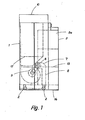
- Fig. 1 ein mobiles Aubsauggerät gemäß der Erfindung, in einer Seitenansicht,
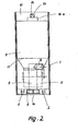
- Fig. 2 das Absauggerät nach Fig.1, in einer Ansicht von hinten,
- Fig. 3 das Absauggerät nach Fig. 1, in einer Ansicht von vorne,
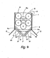
- Fig. 4 das Absauggerät nach Fig. 1, in einer Draufsicht,
- Fig. 5 die Prüf-Filterpatrone des Absauggerätes nach Fig. 1, in einer Seitenansicht,
- Fig. 6 die Prüf-Filterpatrone nach Fig. 5, in einer anderen Seitenansicht,
- Fig. 7 die Prüf-Filterpatrone nach Fig. 5, in einer Draufsicht, und
- Fig. 8 einen Ausschnitt des Schrankgehäuses des und 9 Absauggerätes nach Fig. 1, entsprechend der Einzelheit "A" der Fig. 4, in der Draufsicht bzw. in einer Seitenansicht und in einem anderen Maßstab.
- Das in der Zeichnung dargestellte mobile Absauggerät für Stäube, Farbnebel, Dämpfe und dergleichen weist ein geschlossenes, schrankartiges Blechgehäuse 1 auf, das an seiner Unterseite Rollen 2 trägt, mittels derer es auf dem Fußboden verfahrbar ist. Die Rollen 2 sind mit einem lösbaren Feststeller versehen. Die vordere Seitenwand 3 des Schrankgehäuses 1 ist in der insbesondere aus den Fig. 3 und 4 ersichtlichen Weise giebel- oder dreiecksförmig vorspringend ausgebildete so daß sich zwei einen Winkel von etwa 90° miteinander einschließende Teilflächen,3a,3b ergeben, die luftdurchlässig als Filterflächen ausgebildet sind. Zu diesem Zwecke sind an den Flächen 3a,3b zwei Lagen Filterkassetten 4,4a abgedichtet und lösbar mit dem Schrankgehäuse 1 verbunden. Die Filterkassetteh 4, 4a bilden zwei Schwebstoffilter; sie können, sowie ihr maximal zulässiger Verschmutzungsgrad erreicht ist, von dem Schrankgehäuse 1 abgenommen und durch neue Filterkassetten ersetzt werden.
- .In dem Schrankgehäuse 1 ist ein Gebläse 5 angeordnet, dessen Gebläserad vom einem Elektromotor 6 angetrieben ist, der in dem Schrankgehäuse 1 vollständig gekapselt untergebracht ist. Die bei 7 angedeutete Kapselung ist über einen eigenen Zu- und Abluftkanal 8 mit der Atmosphäre verbunden, wobei der Zuluftkanal bei 9 auf der der durch die Filterkassetten 4, 4a gebildeten Filterfläche gegenüberliegenden Rückseite des Schrankgehäuses 1 mündet, wie dies aus Fig. 2 zu ersehen ist.
- Das Gebläse 5 erzeugt im Inneren des Schrankgehäuses 1 einen Unterdrücke unter dessen Wirkung durch die an der Vorderseite des Schrankgehäuses 1 angeordnete Filterfläche bei 4 großflächig verschmutzte Raumluft angesaugt wird, die nach der Reinigung im Umluftbetrieb über einen an der Oberseite des Schrankgehäuses 1 bei 10 vorhandenen Luftauslaß wieder in den Raum zurückgefördert wird.
- Den Filterkassetten 4,4a kann wenigstens ein in dem Schrankgehäuse angeordnetes weiteres Schwebstoff-Filter 11 nachgeschaltet sein, das auf der Druckseite des Gebläses 5 angeordnet ist. Dem Schwebstoff-Filter 11 ist dann seinerseits ein ebenfalls in dem Schrankgehäuse 1 angeordnetes Aktivkohlefilter 12 (vergl. Fig. 4 bis 7) nachgeschaltet.
- In den Schwebstoff-Filtern 4,4a,11 werden die in der verschmutzten Luft enthaltenen Staubanteile ausgefiltert, während das.Aktivkohlefilter 12 zur Absorption von in der Luft enthaltenen Lösungsmitteldämpfen dient.
- Um die Absaugzone zu begrenzen und den jeweiligen örtlichen Gegebenheiten anpassen zu können, sind an dem Schrankgehäuse 1 zu beiden Seiten der Vorderwand 3 zwei verstellbare Abschirmwände 13 angelenkt, die um vertikale Gelenkachsen verschwenkt werden können. Zur Erhöhung der Absaugwirkung ist das Schrankgehäuse im Bereiche seiner Vorderwand 3 durch eine Bürstenleiste 14 gegen den Fußboden abgedichtet. Die Bürstenleiste 14 erstreckt sich auch über die Unterkante der Abschirmwände 13, so daß auch an dieser Stelle eine Abdichtung gegen den Fußboden vorhanden ist.
- Das Aktivkohlefilter 12 ist durch eine Anzahl Filterpatronen 16 gebildet, die auf einen in dem Schrankgehäuse 1 angeordneten, an die Druckseite des Gebläses 5 angeschlossenen Luftleittrichter 17 abgedichtet aufgesetzt sind, der den einzelnen Filterpatronen.16 zugeordnete Luftdurchlässe 18 (Fig. 5) aufweist, die in . die Filterpatronen münden.
- Jede der Filterpatronen 16 weist einen zu dem : jeweiligen Luftdurchlaß 18 des Luftleittrichters 17 hin sich konisch verjüngenden, mit Aktivkohle gefüllten ringförmigen Filterraum 19 auf (vergl. bspw. Fig. 5), was einerseits lufttechnisch günstig ist, weil der Luftdurchsatz, wie er durch Pfeile 20 in Fig. 5 angedeutet ist, in zunehmendem Abstand von dem Luftdurchlaß 18 zunimmt und andererseits sich hinsichtlich der Standzeit der Filterpatronen als günstig erwiesen hat. Ein dichtschließendes oberes Kunststoffpolster 25 verhindert bei der durch Rütteln der Aktivkohle auftretenden Volumenverminderung das Auftreten von Kurzschlüssen beim Filtervorgang.
- Der Verschmutzungs- und Beladungsgrad der einzelnen Filter 4,4a,11,12 kann getrennt überwacht werden. Zu diesem Zwecke sind eigene Überwachungseinrichtungen vorgesehen, die anzeigen, wann die einzelnen Filter wegen Erreichen der zulässigen maximalen Verschmutzung oder Beladung ausgetauscht werden müssen.
- Zu diesem Zwecke sind den Filterkassetten 4,4a bei 21 in Fig. 4 angedeutete Differenzdruck-Meßgeräte zugeordnet, die den über den Filterkassetten auftretenden Druckabfall messen und über in dem Schrankgehäuse 1 verlaufende Meßleitungen mit Anzeigegeräten (Fig. 3) an der Schrankgehäusevorderseite verbunden sind. Über die Differenzdruck-Messung erfolgt nicht nur eine Kontrolle des Verschmutzungsgrades der Filter, sondern gleichzeitig auch eine Überwachung der umgewälzten Luftmenge, die damit unter Kontrolle gehalten-werden kann. Es können Umschalteinrichtungen vorgesehen sein, um die Filter einzeln kontrollieren zu können.
- Zur Überwachung des Beladungszustandes des Aktivkohlefilters 12 ist die Anordnung derart getroffen, daß eine der nach Art von Filterkerzen gestalteten Filterpatronen 16 - nämlich die Filterpatrone 16a in Fig. 4 - als Prüf-Filterpatrone ausgebildet und mit einer Waage 24 verbunden ist, deren von außen sichtbarer Zeiger 26 das Gewicht der Prüf-Filterpatrone 16a und damit die Schadstoffbeladung anzeigt.
- Zu diesem Zwecke ist die Prüf-Filterpatrone 16 über eine flüssigkeitsgefüllte Labyrinthdichtung 27 begrenzt höhenverstellbar mit dem Luftleittrichter 17 verbünden. Sie ist in dem Schrankgehäuse 1 über ortsfest angeordnete Rollen 28 und über diese geleitete Seilzüge 29 höhenverstellbar aufgehängt, wobei die Seilzüge 29 endseitig mit Ausgleichsgewichten 30.verbunden sind, die das Gewicht der Prüf-Filterpatrone 16 a im unbeladenen Zustand austarieren.
- Die Filterpatronen 16,16a weisen jeweils aus dem Filterraum 19 ins Freie mündende Luftauslaßöffnungen bei 31 auf, die gemeinsam den Luftauslaß 10 des Schrankgehäuses 1'bilden.
- Beispielsweise wenn von einer Montagegrube aus ein sogenannter Unterbodenschutz auf die Unterseite eines Kraftfahrzeuges aufgesprüht wird, besteht die Gefahr, daß sich in der Montagegrube eine unzulässig hohe Konzentration der Lösungsmitteldämpfe einstellt, die daher rührt, daß das spezifische Gewicht des Lösungsmittels höher ist als jenes der Luft. Um das Absauggerät auch für solche Fälle einsetzen zu können, kann die Filterfläche 4,4a nach außen zu durch einen vorgesetzten, etwa mittels Vorreibern an dem Schrankgehäuse 1 lösbar befestigten Luftsammeltrichter 50 abgedeckt sein, der einen Saugstutzen 51 zum Anschluß flexibler Luftabsaugschläuche trägt, die mit ihrem freien Ende in die Montagegrube gelegt werden, um die sich dort ansammelnden Lösungsmittel, Stäube und dergl. abzusaugen. Die Luftsammeltrichter 50 mit den zugeordneten Saugstutzen 51 sind in den Fig. 3,4 gestrichelt eingezeichnet.
- Das Schrankgehäuse 1 ist derart aufgebaut, daß es in der aus den Fig. 8,9 ersichtlichen Weise leistenartige Eckprofile 52 mit einer etwa C-förmigen Querschnittsgestalt aufweist, mit denen plattenartige Wandteile 53,54 bei 55 verschraubt sind. In die C-förmigen Eckprofile 52 sind deren Innenumrißgestalt entsprechende Profilstücke 56 eingefügt, auf denen Konsolen oder dergl. des Schrankgehäuses 1 abgestützt sind, auf welchen ihrerseits die in dem Schrankgehäuse 1 untergebrachten Elemente befestigt und angeordnet sind. Die Profilstücke 56 sind mit den Eckprofilen 52 ebenfalls bei 55 verschraubt.
Claims (19)
Priority Applications (1)
| Application Number | Priority Date | Filing Date | Title |
|---|---|---|---|
| AT82105088T ATE21635T1 (de) | 1981-06-13 | 1982-06-10 | Mobiles absauggeraet fuer staeube, farbnebel, daempfe und dergleichen. |
Applications Claiming Priority (2)
| Application Number | Priority Date | Filing Date | Title |
|---|---|---|---|
| DE19813123571 DE3123571A1 (de) | 1981-06-13 | 1981-06-13 | Mobiles absaugegeraet im umluftverfahren |
| DE3123571 | 1981-06-13 |
Publications (3)
| Publication Number | Publication Date |
|---|---|
| EP0067422A2 true EP0067422A2 (de) | 1982-12-22 |
| EP0067422A3 EP0067422A3 (en) | 1983-03-30 |
| EP0067422B1 EP0067422B1 (de) | 1986-08-27 |
Family
ID=6134682
Family Applications (1)
| Application Number | Title | Priority Date | Filing Date |
|---|---|---|---|
| EP82105088A Expired EP0067422B1 (de) | 1981-06-13 | 1982-06-10 | Mobiles Absauggerät für Stäube, Farbnebel, Dämpfe und dergleichen |
Country Status (3)
| Country | Link |
|---|---|
| EP (1) | EP0067422B1 (de) |
| AT (1) | ATE21635T1 (de) |
| DE (2) | DE3123571A1 (de) |
Cited By (3)
| Publication number | Priority date | Publication date | Assignee | Title |
|---|---|---|---|---|
| RU2202404C1 (ru) * | 2002-02-15 | 2003-04-20 | Закрытое акционерное общество "Металлхим-Прогресс" | Установка для очистки загрязненного воздуха |
| DE102009038069A1 (de) * | 2009-08-19 | 2011-02-24 | Heinrich Stumpf | Absaugvorrichtung |
| EP2532409B1 (de) | 2011-06-08 | 2018-02-14 | Neufilter GmbH | Papiergelegefiltermodul, Verfahren zur Herstellung eines solchen Papiergelegefiltermoduls und Papiergelegefiltermodulwand aus einer Mehrzahl derartiger Papiergelegefiltermodule |
Family Cites Families (6)
| Publication number | Priority date | Publication date | Assignee | Title |
|---|---|---|---|---|
| DE1150789B (de) * | 1957-10-30 | 1963-06-27 | Georg Moessmer Dipl Ing | Absaugvorrichtung fuer Steinmetzarbeiten |
| US3747502A (en) * | 1971-06-14 | 1973-07-24 | J Williams | Air pollution control system |
| SE384637B (sv) * | 1974-09-02 | 1976-05-17 | J O Olsson | Ventilationsaggregat med bojlig rorledning |
| DE2621172A1 (de) * | 1976-05-11 | 1977-12-01 | Gerhard Max Neumann | Raumluft-reinigungsgeraet |
| SE7812139L (sv) * | 1978-11-24 | 1980-05-25 | Svenska Flaektfabriken Ab | Utsugningsbox |
| DE2934246A1 (de) * | 1979-08-24 | 1981-03-26 | Hartwig 74744 Ahorn Straub | Aktivkohlefilter |
-
1981
- 1981-06-13 DE DE19813123571 patent/DE3123571A1/de not_active Withdrawn
-
1982
- 1982-06-10 DE DE8282105088T patent/DE3272875D1/de not_active Expired
- 1982-06-10 AT AT82105088T patent/ATE21635T1/de not_active IP Right Cessation
- 1982-06-10 EP EP82105088A patent/EP0067422B1/de not_active Expired
Cited By (3)
| Publication number | Priority date | Publication date | Assignee | Title |
|---|---|---|---|---|
| RU2202404C1 (ru) * | 2002-02-15 | 2003-04-20 | Закрытое акционерное общество "Металлхим-Прогресс" | Установка для очистки загрязненного воздуха |
| DE102009038069A1 (de) * | 2009-08-19 | 2011-02-24 | Heinrich Stumpf | Absaugvorrichtung |
| EP2532409B1 (de) | 2011-06-08 | 2018-02-14 | Neufilter GmbH | Papiergelegefiltermodul, Verfahren zur Herstellung eines solchen Papiergelegefiltermoduls und Papiergelegefiltermodulwand aus einer Mehrzahl derartiger Papiergelegefiltermodule |
Also Published As
| Publication number | Publication date |
|---|---|
| EP0067422A3 (en) | 1983-03-30 |
| EP0067422B1 (de) | 1986-08-27 |
| ATE21635T1 (de) | 1986-09-15 |
| DE3123571A1 (de) | 1982-12-30 |
| DE3272875D1 (en) | 1986-10-02 |
Similar Documents
| Publication | Publication Date | Title |
|---|---|---|
| EP0211383B1 (de) | Filtergerät | |
| DE2716317C2 (de) | ||
| US20090253360A1 (en) | Portable Ventilation Unit | |
| DE102009055192A1 (de) | Filtervorrichtung zum Abtrennen von Lack-Overspray | |
| EP0909577A2 (de) | Mobile Anlage zum Reinigen kontaminierter Luft | |
| EP3921057A1 (de) | Verfahren zum filterwechsel und entstaubungsanlage | |
| EP0636337A1 (de) | Staubsauger mit einem Filter | |
| EP0067422B1 (de) | Mobiles Absauggerät für Stäube, Farbnebel, Dämpfe und dergleichen | |
| DE102018124928A1 (de) | Laborabzug | |
| DE202015009698U1 (de) | Filteranlage zur Filtrierung von, insbesondere kontaminierten, Luftstäuben | |
| EP0598246B1 (de) | Zahntechnischer Arbeitsplatz mit einem Arbeitstisch und einer Absaugeinrichtung mit einem Filtergerät | |
| EP2072146A2 (de) | Modulartig zusammengesetzte Beschichtungszelle | |
| DE595002C (de) | Spritzanlage mit offener Arbeitsseite | |
| DE4235700C2 (de) | Filtergerät für ein gasförmiges Medium | |
| DE4122699C2 (de) | Arbeitsplatz für die Behandlung schadstoffbelasteter Teile | |
| DE4321869A1 (de) | Vorrichtung zum Entfernen von sich auf Textilmaschinen absetzendem Flug | |
| DE4143113A1 (de) | Vorrichtung zur reinigung der waende von hochragenden bauwerken, insbesondere von kuehltuermen, schornsteinen, silos o. dgl. | |
| DE2711255C2 (de) | Straßenreinigungsmaschine | |
| DE3303534C2 (de) | ||
| DE4140490A1 (de) | Spritzkabine fuer das aufbringen von stark wasserhaltigen email- oder keramikglasuren auf entsprechende werkstuecke | |
| EP0509052B1 (de) | Vorrichtung zum reinigen mechanischer geräte, kleinteile und/oder elektronischer schalteinheiten | |
| DE8522286U1 (de) | Filtergerät | |
| EP0503449A1 (de) | Filtervorrichtung | |
| DE3438651A1 (de) | Verfahren und vorrichtung zum reinigen mechanischer geraete, kleinteile und/oder elektronischer schalteinheiten | |
| DE9317643U1 (de) | Schweißrauch-Absauganlage |
Legal Events
| Date | Code | Title | Description |
|---|---|---|---|
| PUAI | Public reference made under article 153(3) epc to a published international application that has entered the european phase |
Free format text: ORIGINAL CODE: 0009012 |
|
| AK | Designated contracting states |
Designated state(s): AT BE CH DE FR GB IT LI LU NL SE |
|
| PUAL | Search report despatched |
Free format text: ORIGINAL CODE: 0009013 |
|
| AK | Designated contracting states |
Designated state(s): AT BE CH DE FR GB IT LI LU NL SE |
|
| 17P | Request for examination filed |
Effective date: 19830629 |
|
| GRAA | (expected) grant |
Free format text: ORIGINAL CODE: 0009210 |
|
| AK | Designated contracting states |
Kind code of ref document: B1 Designated state(s): AT BE CH DE FR GB IT LI LU NL SE |
|
| PG25 | Lapsed in a contracting state [announced via postgrant information from national office to epo] |
Ref country code: NL Effective date: 19860827 |
|
| REF | Corresponds to: |
Ref document number: 21635 Country of ref document: AT Date of ref document: 19860915 Kind code of ref document: T |
|
| ITF | It: translation for a ep patent filed | ||
| PG25 | Lapsed in a contracting state [announced via postgrant information from national office to epo] |
Ref country code: SE Effective date: 19860831 |
|
| RAP2 | Party data changed (patent owner data changed or rights of a patent transferred) |
Owner name: HANKE, MARTIN |
|
| REF | Corresponds to: |
Ref document number: 3272875 Country of ref document: DE Date of ref document: 19861002 |
|
| ET | Fr: translation filed | ||
| NLV1 | Nl: lapsed or annulled due to failure to fulfill the requirements of art. 29p and 29m of the patents act | ||
| PG25 | Lapsed in a contracting state [announced via postgrant information from national office to epo] |
Ref country code: LU Free format text: LAPSE BECAUSE OF NON-PAYMENT OF DUE FEES Effective date: 19870630 |
|
| PLBE | No opposition filed within time limit |
Free format text: ORIGINAL CODE: 0009261 |
|
| STAA | Information on the status of an ep patent application or granted ep patent |
Free format text: STATUS: NO OPPOSITION FILED WITHIN TIME LIMIT |
|
| 26N | No opposition filed | ||
| PGFP | Annual fee paid to national office [announced via postgrant information from national office to epo] |
Ref country code: LU Payment date: 19890526 Year of fee payment: 8 Ref country code: AT Payment date: 19890526 Year of fee payment: 8 |
|
| PGFP | Annual fee paid to national office [announced via postgrant information from national office to epo] |
Ref country code: GB Payment date: 19890531 Year of fee payment: 8 |
|
| PGFP | Annual fee paid to national office [announced via postgrant information from national office to epo] |
Ref country code: FR Payment date: 19890622 Year of fee payment: 8 |
|
| PGFP | Annual fee paid to national office [announced via postgrant information from national office to epo] |
Ref country code: BE Payment date: 19890626 Year of fee payment: 8 |
|
| ITTA | It: last paid annual fee | ||
| PGFP | Annual fee paid to national office [announced via postgrant information from national office to epo] |
Ref country code: CH Payment date: 19890630 Year of fee payment: 8 |
|
| PG25 | Lapsed in a contracting state [announced via postgrant information from national office to epo] |
Ref country code: GB Effective date: 19900610 Ref country code: AT Effective date: 19900610 |
|
| PG25 | Lapsed in a contracting state [announced via postgrant information from national office to epo] |
Ref country code: LI Effective date: 19900630 Ref country code: CH Effective date: 19900630 Ref country code: BE Effective date: 19900630 |
|
| BERE | Be: lapsed |
Owner name: HANKE MARTIN Effective date: 19900630 |
|
| GBPC | Gb: european patent ceased through non-payment of renewal fee | ||
| PG25 | Lapsed in a contracting state [announced via postgrant information from national office to epo] |
Ref country code: FR Effective date: 19910228 |
|
| REG | Reference to a national code |
Ref country code: CH Ref legal event code: PL |
|
| REG | Reference to a national code |
Ref country code: FR Ref legal event code: ST |
|
| PGFP | Annual fee paid to national office [announced via postgrant information from national office to epo] |
Ref country code: DE Payment date: 19910816 Year of fee payment: 10 |
|
| PG25 | Lapsed in a contracting state [announced via postgrant information from national office to epo] |
Ref country code: DE Effective date: 19930302 |