EP0067422A2 - Dispositif mobile d'aspiration pour la poussière, l'air contaminé par de la peinture, des vapeurs et analoques - Google Patents
Dispositif mobile d'aspiration pour la poussière, l'air contaminé par de la peinture, des vapeurs et analoques Download PDFInfo
- Publication number
- EP0067422A2 EP0067422A2 EP82105088A EP82105088A EP0067422A2 EP 0067422 A2 EP0067422 A2 EP 0067422A2 EP 82105088 A EP82105088 A EP 82105088A EP 82105088 A EP82105088 A EP 82105088A EP 0067422 A2 EP0067422 A2 EP 0067422A2
- Authority
- EP
- European Patent Office
- Prior art keywords
- filter
- suction device
- cabinet housing
- air
- blower
- Prior art date
- Legal status (The legal status is an assumption and is not a legal conclusion. Google has not performed a legal analysis and makes no representation as to the accuracy of the status listed.)
- Granted
Links
Images



Classifications
-
- B—PERFORMING OPERATIONS; TRANSPORTING
- B08—CLEANING
- B08B—CLEANING IN GENERAL; PREVENTION OF FOULING IN GENERAL
- B08B15/00—Preventing escape of dirt or fumes from the area where they are produced; Collecting or removing dirt or fumes from that area
-
- A—HUMAN NECESSITIES
- A62—LIFE-SAVING; FIRE-FIGHTING
- A62B—DEVICES, APPARATUS OR METHODS FOR LIFE-SAVING
- A62B11/00—Devices for reconditioning breathing air in sealed rooms
Definitions
- the invention relates to a mobile suction device for dusts, paint mist, vapors and the like.
- the object of the invention is therefore to provide a mobile, user-friendly suction device which allows local pollutant concentrations to be prevented in air-polluting work in workshops or the like, without the need for stationary air lines and the like.
- the mobile suction device is characterized in that it has a portable, all-round closed cabinet housing, in which a blower generating a vacuum is arranged in the interior of the housing and in which a side wall is at least partially designed as a filter surface through which a large area is contaminated Room air can be sucked in, which can be conveyed back into the room via an air outlet of the cabinet housing after cleaning in recirculation mode.
- the portable cabinet housing can be brought directly to the location of the pollutant accumulation, the pollutants being sucked off on the spot.
- the cleaned air is recirculated back into the work area, with the result that there is no need to connect to exhaust air ducts leading to the outside atmosphere.
- a large-area suction effect is exerted on the filter surface, for example on a paint mist generated by a paint spray gun.
- the device has at least one suspended matter filter arranged in the cabinet housing, which is connected downstream of the filter surface - which then in turn acts as a suspended matter prefilter.
- the particulate filter is advantageously arranged on the pressure side of the blower. It is used to filter out the dust content of the polluted air.
- the suspended matter filter is followed by an activated carbon filter arranged in the cabinet housing.
- the filter surface provided in the region of the front side wall of the cabinet housing is expediently formed by filter cassettes which are sealed and releasably connected to the cabinet housing. These filter cartridges can be easily replaced if they are dirty, without requiring any special intervention in the suction device itself.
- adjustable shielding walls can be arranged on the cabinet housing in the area of the boundary of the filter surface, by means of which the suction zone is limited.
- the cabinet housing can be sealed against the floor at least in the area of the filter surface, which also applies to the shielding walls to the same extent. In this way, a uniform horizontal air velocity distribution can be achieved, as is usual with stationary suction walls.
- the electric motor drive of the fan is advantageously encapsulated in the cabinet housing and connected to the atmosphere by a separate supply air and exhaust air duct, from which the supply air duct opens on the side of the cabinet housing opposite the filter surface.
- the encapsulated version of the blower drive prevents the motor from being contaminated by paint mist. Since the cooling air for the motor is drawn in from the rear of the cabinet, solvent mist can be extracted from paints with a flash point above 21 ° C in accordance with the TÜV guidelines.
- the effectiveness of the filters depends on the fact that they are not excessively dirty or loaded.
- the mobile suction device therefore advantageously has monitoring devices arranged in the cabinet housing for the degree of contamination or loading of the individual filters.
- at least one of the filters can be assigned a differential pressure measuring device which determines the pressure drop occurring on the filter.
- the absorption of the color thinners consisting of aromatic hydrocarbons by the activated carbon of the activated carbon filter leads to an increase in the weight of the filter.
- This increase in weight can be used for monitoring in that the activated carbon filter is assigned a weighing device which has a display device, which displays the increase in weight and, if necessary, lights up a warning light arranged on the cabinet housing in a visible position in order to indicate that the activated carbon filter is desorbed or replaced got to.
- the activated carbon filter is formed by a number of filter cartridges which are placed in a sealed manner on an air guide funnel which is arranged in the cabinet housing and is connected to the pressure side of the blower and has air passages assigned to the individual filter cartridges which lead into the filter cartridges.
- one of the filter cartridges can be connected to the control device as a test filter cartridge and can be connected to the air guide funnel in a sealed manner to a limited extent via a liquid-filled labyrinth seal.
- the filter cartridges have an annular filter space which tapers conically towards the respective air passage and is filled with activated carbon.
- the air outlet of the cabinet housing is formed directly by the air outlet openings of the filter cartridges opening into the open.
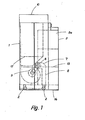
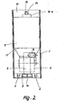
- the mobile suction device for dusts, paint mist, vapors and the like shown in the drawing has a closed, cabinet-like sheet metal housing 1 which carries rollers 2 on its underside, by means of which it can be moved on the floor.
- the rollers 2 are provided with a detachable lock.
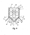
- the front side wall 3 of the cabinet housing 1 is formed in the manner shown in FIGS. 3 and 4 in a gable or triangular projecting manner so that there are two partial surfaces 3a, 3b enclosing an angle of approximately 90 °, which are air-permeable as filter surfaces are.
- two layers of filter cassettes 4,4a are sealed on the surfaces 3a, 3b and releasably connected to the cabinet housing 1.
- the filter cassettes 4, 4a form two suspended matter filters; they can be removed from the cabinet housing 1 and replaced with new filter cartridges as soon as their maximum permissible degree of contamination has been reached.
- a fan 5 is arranged, the impeller of which is driven by an electric motor 6, which is housed in the cabinet housing 1 completely encapsulated.
- the encapsulation indicated at 7 is connected to the atmosphere via its own supply and exhaust air duct 8, the supply air duct at 9 on the through the filter cassettes 4, 4a formed filter surface opposite the rear of the cabinet housing 1 opens, as can be seen from Fig. 2.
- the blower 5 generates a negative pressure inside the cabinet housing 1 under the effect of which is sucked in by the filter surface arranged at the front of the cabinet housing 1 at 4 large-area contaminated room air, which after cleaning in recirculation mode via an air outlet at 10 on the top of the cabinet housing 1 is conveyed back into the room.
- the filter cassettes 4, 4a can be followed by at least one further suspended matter filter 11 arranged in the cabinet housing, which is arranged on the pressure side of the blower 5.
- the suspended matter filter 11 is then in turn connected to an activated carbon filter 12 (see FIGS. 4 to 7) which is also arranged in the cabinet housing 1.
- the dust components contained in the polluted air are filtered out, while the activated carbon filter 12 serves to absorb solvent vapors contained in the air.
- two adjustable shielding walls 13 are articulated on the cabinet housing 1 on both sides of the front wall 3 and can be pivoted about vertical joint axes.
- the brush strip 14 also extends over the lower edge of the shielding walls 13, so that a seal against the floor is also present at this point.
- the activated carbon filter 12 is formed by a number of filter cartridges 16, which are placed in a sealed manner on an air guide funnel 17 which is arranged in the cabinet housing 1 and is connected to the pressure side of the blower 5 and which holds the individual filter cartridges . 16 associated air passages 18 (Fig. 5), which in. the filter cartridges open.
- Each of the filter cartridges 16 has a ring-shaped filter chamber 19 which tapers conically towards the respective air passage 18 of the air guide funnel 17 and is filled with activated carbon (see, for example, FIG. 5), which is technically favorable on the one hand because of the air throughput as it passes through Arrows 20 in Fig. 5 is indicated, increases with increasing distance from the air passage 18 and on the other hand has proven to be favorable with regard to the service life of the filter cartridges.
- a tightly closing upper plastic cushion 25 prevents the occurrence of short circuits during the filtering process in the event of a reduction in volume caused by shaking the activated carbon.
- the degree of contamination and loading of the individual filters 4,4a, 11,12 can be monitored separately.
- separate monitoring devices are provided, which indicate when the individual filters must be replaced due to reaching the permissible maximum contamination or load.
- the filter cartridges 4,4a at 21 in Fig. 4 are assigned differential pressure measuring devices which measure the pressure drop occurring across the filter cartridges and are connected via measuring lines running in the cabinet housing 1 to display devices (Fig. 3) on the front of the cabinet housing.
- the differential pressure measurement not only controls the degree of contamination of the filters, but also monitors the amount of air circulated, which can be kept under control. Switching devices can be provided in order to be able to control the filters individually.
- the arrangement is such that one of the filter cartridges 16 designed in the manner of filter candles - namely the filter cartridge 16a in FIG. 4 - is designed as a test filter cartridge and is connected to a balance 24, the latter of which is visible from the outside Pointer 26 indicates the weight of the test filter cartridge 16a and thus the pollutant load.
- test filter cartridge 16 is connected to the air guide funnel 17 to a limited extent via a liquid-filled labyrinth seal 27. It is suspended in a height-adjustable manner in the cabinet housing 1 by means of rollers 28 which are arranged in a stationary manner and by means of the cables 29 guided thereon, the cables 29 being connected at the end to counterweights 30 which balance the weight of the test filter cartridge 16a in the unloaded state.
- the filter cartridges 16, 16a each have air outlet openings 31 which open out of the filter chamber 19 and together form the air outlet 10 of the cabinet housing 1 '.
- the filter surface 4, 4a can be covered to the outside by a superior air collecting funnel 50, which is detachably fastened to the cabinet housing 1 by means of sashes, for example, which carries a suction nozzle 51 for connecting flexible air suction hoses, which are connected with be placed at the free end in the assembly pit in order to suck off the solvents, dusts and the like that collect there.
- the air collection funnels 50 with the associated suction ports 51 are shown in broken lines in FIGS.
- the cabinet housing 1 is constructed in such a way that it has, in the manner shown in FIGS. 8.9, strip-like corner profiles 52 with an approximately C-shaped cross-sectional shape, to which plate-like wall parts 53, 54 are screwed at 55.
- strip-like corner profiles 52 with an approximately C-shaped cross-sectional shape, to which plate-like wall parts 53, 54 are screwed at 55.
- C-shaped corner profiles 52 are corresponding internal pieces 56 inserted, on which brackets or the like of the cabinet housing 1 are supported, on which in turn the elements accommodated in the cabinet housing 1 are fastened and arranged.
- the profile pieces 56 are also screwed to the corner profiles 52 at 55.
Landscapes
- Health & Medical Sciences (AREA)
- Pulmonology (AREA)
- General Health & Medical Sciences (AREA)
- Business, Economics & Management (AREA)
- Emergency Management (AREA)
- Filtering Of Dispersed Particles In Gases (AREA)
- Prevention Of Fouling (AREA)
- Details Or Accessories Of Spraying Plant Or Apparatus (AREA)
- Physical Or Chemical Processes And Apparatus (AREA)
Priority Applications (1)
| Application Number | Priority Date | Filing Date | Title |
|---|---|---|---|
| AT82105088T ATE21635T1 (de) | 1981-06-13 | 1982-06-10 | Mobiles absauggeraet fuer staeube, farbnebel, daempfe und dergleichen. |
Applications Claiming Priority (2)
| Application Number | Priority Date | Filing Date | Title |
|---|---|---|---|
| DE19813123571 DE3123571A1 (de) | 1981-06-13 | 1981-06-13 | Mobiles absaugegeraet im umluftverfahren |
| DE3123571 | 1981-06-13 |
Publications (3)
| Publication Number | Publication Date |
|---|---|
| EP0067422A2 true EP0067422A2 (fr) | 1982-12-22 |
| EP0067422A3 EP0067422A3 (en) | 1983-03-30 |
| EP0067422B1 EP0067422B1 (fr) | 1986-08-27 |
Family
ID=6134682
Family Applications (1)
| Application Number | Title | Priority Date | Filing Date |
|---|---|---|---|
| EP82105088A Expired EP0067422B1 (fr) | 1981-06-13 | 1982-06-10 | Dispositif mobile d'aspiration pour la poussière, l'air contaminé par de la peinture, des vapeurs et analoques |
Country Status (3)
| Country | Link |
|---|---|
| EP (1) | EP0067422B1 (fr) |
| AT (1) | ATE21635T1 (fr) |
| DE (2) | DE3123571A1 (fr) |
Cited By (3)
| Publication number | Priority date | Publication date | Assignee | Title |
|---|---|---|---|---|
| RU2202404C1 (ru) * | 2002-02-15 | 2003-04-20 | Закрытое акционерное общество "Металлхим-Прогресс" | Установка для очистки загрязненного воздуха |
| DE102009038069A1 (de) * | 2009-08-19 | 2011-02-24 | Heinrich Stumpf | Absaugvorrichtung |
| EP2532409B1 (fr) | 2011-06-08 | 2018-02-14 | Neufilter GmbH | Module de filtre en papier non tissé, procédé de fabrication d'un tel module de filtre en papier non tissé et paroi de module de filtre en papier non tissé à partir de plusieurs modules de filtre en papier non tissé de ce type |
Family Cites Families (6)
| Publication number | Priority date | Publication date | Assignee | Title |
|---|---|---|---|---|
| DE1150789B (de) * | 1957-10-30 | 1963-06-27 | Georg Moessmer Dipl Ing | Absaugvorrichtung fuer Steinmetzarbeiten |
| US3747502A (en) * | 1971-06-14 | 1973-07-24 | J Williams | Air pollution control system |
| SE384637B (sv) * | 1974-09-02 | 1976-05-17 | J O Olsson | Ventilationsaggregat med bojlig rorledning |
| DE2621172A1 (de) * | 1976-05-11 | 1977-12-01 | Gerhard Max Neumann | Raumluft-reinigungsgeraet |
| SE7812139L (sv) * | 1978-11-24 | 1980-05-25 | Svenska Flaektfabriken Ab | Utsugningsbox |
| DE2934246A1 (de) * | 1979-08-24 | 1981-03-26 | Hartwig 74744 Ahorn Straub | Aktivkohlefilter |
-
1981
- 1981-06-13 DE DE19813123571 patent/DE3123571A1/de not_active Withdrawn
-
1982
- 1982-06-10 DE DE8282105088T patent/DE3272875D1/de not_active Expired
- 1982-06-10 AT AT82105088T patent/ATE21635T1/de not_active IP Right Cessation
- 1982-06-10 EP EP82105088A patent/EP0067422B1/fr not_active Expired
Cited By (3)
| Publication number | Priority date | Publication date | Assignee | Title |
|---|---|---|---|---|
| RU2202404C1 (ru) * | 2002-02-15 | 2003-04-20 | Закрытое акционерное общество "Металлхим-Прогресс" | Установка для очистки загрязненного воздуха |
| DE102009038069A1 (de) * | 2009-08-19 | 2011-02-24 | Heinrich Stumpf | Absaugvorrichtung |
| EP2532409B1 (fr) | 2011-06-08 | 2018-02-14 | Neufilter GmbH | Module de filtre en papier non tissé, procédé de fabrication d'un tel module de filtre en papier non tissé et paroi de module de filtre en papier non tissé à partir de plusieurs modules de filtre en papier non tissé de ce type |
Also Published As
| Publication number | Publication date |
|---|---|
| EP0067422A3 (en) | 1983-03-30 |
| EP0067422B1 (fr) | 1986-08-27 |
| ATE21635T1 (de) | 1986-09-15 |
| DE3123571A1 (de) | 1982-12-30 |
| DE3272875D1 (en) | 1986-10-02 |
Similar Documents
| Publication | Publication Date | Title |
|---|---|---|
| EP0211383B1 (fr) | Filtre | |
| DE2716317C2 (fr) | ||
| US20090253360A1 (en) | Portable Ventilation Unit | |
| DE102009055192A1 (de) | Filtervorrichtung zum Abtrennen von Lack-Overspray | |
| EP0909577A2 (fr) | Appareil mobile pour l'epuration de l'air pollué | |
| EP3921057A1 (fr) | Procédé pour changer un filtre et système de dépoussiérage | |
| EP0636337A1 (fr) | Filtre pour aspirateur | |
| EP0067422B1 (fr) | Dispositif mobile d'aspiration pour la poussière, l'air contaminé par de la peinture, des vapeurs et analoques | |
| DE102018124928A1 (de) | Laborabzug | |
| DE202015009698U1 (de) | Filteranlage zur Filtrierung von, insbesondere kontaminierten, Luftstäuben | |
| EP0598246B1 (fr) | Lieu de travail avec une table de travail et une installation d'aspiration pourvue d'un dispositif de filtrage | |
| EP2072146A2 (fr) | Enceinte de revêtement modulaire | |
| DE595002C (de) | Spritzanlage mit offener Arbeitsseite | |
| DE4235700C2 (de) | Filtergerät für ein gasförmiges Medium | |
| DE4122699C2 (de) | Arbeitsplatz für die Behandlung schadstoffbelasteter Teile | |
| DE4321869A1 (de) | Vorrichtung zum Entfernen von sich auf Textilmaschinen absetzendem Flug | |
| DE4143113A1 (de) | Vorrichtung zur reinigung der waende von hochragenden bauwerken, insbesondere von kuehltuermen, schornsteinen, silos o. dgl. | |
| DE2711255C2 (de) | Straßenreinigungsmaschine | |
| DE3303534C2 (fr) | ||
| DE4140490A1 (de) | Spritzkabine fuer das aufbringen von stark wasserhaltigen email- oder keramikglasuren auf entsprechende werkstuecke | |
| EP0509052B1 (fr) | Dispositif de nettoyage d'appareil mecaniques, de petites pieces et/ou d'unites de commutation electroniques | |
| DE8522286U1 (de) | Filtergerät | |
| EP0503449A1 (fr) | Filtre | |
| DE3438651A1 (de) | Verfahren und vorrichtung zum reinigen mechanischer geraete, kleinteile und/oder elektronischer schalteinheiten | |
| DE9317643U1 (de) | Schweißrauch-Absauganlage |
Legal Events
| Date | Code | Title | Description |
|---|---|---|---|
| PUAI | Public reference made under article 153(3) epc to a published international application that has entered the european phase |
Free format text: ORIGINAL CODE: 0009012 |
|
| AK | Designated contracting states |
Designated state(s): AT BE CH DE FR GB IT LI LU NL SE |
|
| PUAL | Search report despatched |
Free format text: ORIGINAL CODE: 0009013 |
|
| AK | Designated contracting states |
Designated state(s): AT BE CH DE FR GB IT LI LU NL SE |
|
| 17P | Request for examination filed |
Effective date: 19830629 |
|
| GRAA | (expected) grant |
Free format text: ORIGINAL CODE: 0009210 |
|
| AK | Designated contracting states |
Kind code of ref document: B1 Designated state(s): AT BE CH DE FR GB IT LI LU NL SE |
|
| PG25 | Lapsed in a contracting state [announced via postgrant information from national office to epo] |
Ref country code: NL Effective date: 19860827 |
|
| REF | Corresponds to: |
Ref document number: 21635 Country of ref document: AT Date of ref document: 19860915 Kind code of ref document: T |
|
| ITF | It: translation for a ep patent filed | ||
| PG25 | Lapsed in a contracting state [announced via postgrant information from national office to epo] |
Ref country code: SE Effective date: 19860831 |
|
| RAP2 | Party data changed (patent owner data changed or rights of a patent transferred) |
Owner name: HANKE, MARTIN |
|
| REF | Corresponds to: |
Ref document number: 3272875 Country of ref document: DE Date of ref document: 19861002 |
|
| ET | Fr: translation filed | ||
| NLV1 | Nl: lapsed or annulled due to failure to fulfill the requirements of art. 29p and 29m of the patents act | ||
| PG25 | Lapsed in a contracting state [announced via postgrant information from national office to epo] |
Ref country code: LU Free format text: LAPSE BECAUSE OF NON-PAYMENT OF DUE FEES Effective date: 19870630 |
|
| PLBE | No opposition filed within time limit |
Free format text: ORIGINAL CODE: 0009261 |
|
| STAA | Information on the status of an ep patent application or granted ep patent |
Free format text: STATUS: NO OPPOSITION FILED WITHIN TIME LIMIT |
|
| 26N | No opposition filed | ||
| PGFP | Annual fee paid to national office [announced via postgrant information from national office to epo] |
Ref country code: LU Payment date: 19890526 Year of fee payment: 8 Ref country code: AT Payment date: 19890526 Year of fee payment: 8 |
|
| PGFP | Annual fee paid to national office [announced via postgrant information from national office to epo] |
Ref country code: GB Payment date: 19890531 Year of fee payment: 8 |
|
| PGFP | Annual fee paid to national office [announced via postgrant information from national office to epo] |
Ref country code: FR Payment date: 19890622 Year of fee payment: 8 |
|
| PGFP | Annual fee paid to national office [announced via postgrant information from national office to epo] |
Ref country code: BE Payment date: 19890626 Year of fee payment: 8 |
|
| ITTA | It: last paid annual fee | ||
| PGFP | Annual fee paid to national office [announced via postgrant information from national office to epo] |
Ref country code: CH Payment date: 19890630 Year of fee payment: 8 |
|
| PG25 | Lapsed in a contracting state [announced via postgrant information from national office to epo] |
Ref country code: GB Effective date: 19900610 Ref country code: AT Effective date: 19900610 |
|
| PG25 | Lapsed in a contracting state [announced via postgrant information from national office to epo] |
Ref country code: LI Effective date: 19900630 Ref country code: CH Effective date: 19900630 Ref country code: BE Effective date: 19900630 |
|
| BERE | Be: lapsed |
Owner name: HANKE MARTIN Effective date: 19900630 |
|
| GBPC | Gb: european patent ceased through non-payment of renewal fee | ||
| PG25 | Lapsed in a contracting state [announced via postgrant information from national office to epo] |
Ref country code: FR Effective date: 19910228 |
|
| REG | Reference to a national code |
Ref country code: CH Ref legal event code: PL |
|
| REG | Reference to a national code |
Ref country code: FR Ref legal event code: ST |
|
| PGFP | Annual fee paid to national office [announced via postgrant information from national office to epo] |
Ref country code: DE Payment date: 19910816 Year of fee payment: 10 |
|
| PG25 | Lapsed in a contracting state [announced via postgrant information from national office to epo] |
Ref country code: DE Effective date: 19930302 |