EP0068054B1 - Ensemble de lave-glaces - Google Patents
Ensemble de lave-glaces Download PDFInfo
- Publication number
- EP0068054B1 EP0068054B1 EP81303009A EP81303009A EP0068054B1 EP 0068054 B1 EP0068054 B1 EP 0068054B1 EP 81303009 A EP81303009 A EP 81303009A EP 81303009 A EP81303009 A EP 81303009A EP 0068054 B1 EP0068054 B1 EP 0068054B1
- Authority
- EP
- European Patent Office
- Prior art keywords
- connector
- pump
- cover plate
- container
- pegs
- Prior art date
- Legal status (The legal status is an assumption and is not a legal conclusion. Google has not performed a legal analysis and makes no representation as to the accuracy of the status listed.)
- Expired
Links
Images

Classifications
-
- H—ELECTRICITY
- H02—GENERATION; CONVERSION OR DISTRIBUTION OF ELECTRIC POWER
- H02K—DYNAMO-ELECTRIC MACHINES
- H02K5/00—Casings; Enclosures; Supports
- H02K5/04—Casings or enclosures characterised by the shape, form or construction thereof
- H02K5/22—Auxiliary parts of casings not covered by groups H02K5/06-H02K5/20, e.g. shaped to form connection boxes or terminal boxes
- H02K5/225—Terminal boxes or connection arrangements
-
- B—PERFORMING OPERATIONS; TRANSPORTING
- B60—VEHICLES IN GENERAL
- B60S—SERVICING, CLEANING, REPAIRING, SUPPORTING, LIFTING, OR MANOEUVRING OF VEHICLES, NOT OTHERWISE PROVIDED FOR
- B60S1/00—Cleaning of vehicles
- B60S1/02—Cleaning windscreens, windows or optical devices
- B60S1/46—Cleaning windscreens, windows or optical devices using liquid; Windscreen washers
- B60S1/48—Liquid supply therefor
- B60S1/481—Liquid supply therefor the operation of at least part of the liquid supply being controlled by electric means
-
- B—PERFORMING OPERATIONS; TRANSPORTING
- B60—VEHICLES IN GENERAL
- B60S—SERVICING, CLEANING, REPAIRING, SUPPORTING, LIFTING, OR MANOEUVRING OF VEHICLES, NOT OTHERWISE PROVIDED FOR
- B60S1/00—Cleaning of vehicles
- B60S1/02—Cleaning windscreens, windows or optical devices
- B60S1/46—Cleaning windscreens, windows or optical devices using liquid; Windscreen washers
- B60S1/48—Liquid supply therefor
- B60S1/50—Arrangement of reservoir
Definitions
- the present invention relates to a windscreen washer unit of the type defined in the introductory part of claim 1.
- a windscreen washer unit of the type defined in the introductory part of claim 1.
- Such a unit represents a compact and convenient unit which already has wide commercial usage.
- the pump is neatly contained within the typically paralleli- pidal volume defined by the container but is actually outside the container, so that the electric motor cannot be affected by the water in the container.
- the unit is conventionally mounted in a protected position, either inside the engine compartment or behind the dashboard for example. Such a location is not very convenient especially in the case of a tractor or earthworking vehicle used in dirty conditions requiring much use of the windscreen washer and therefore frequent replenishment of the container.
- the driver has L u open up the bonnet or fill the container in an inconvenient cramped location every time it runs dry.
- the broad object of the present invention is to avoid such problems by providing a unit which can be mounted externally on the vehicle, where it can easily be replenished. Another problem then arises in that the electrical connector is exposed and, especially in dirty conditions, will become contaminated and subject to corrosion of the contact elements, so leading to poor electrical connections. It is a more specific object to overcome this further problem and the solution to the problems according to the invention is defined in the characterising part of claim 1.
- a further problem is that, although several pump manufacturers have standardised their pumps in many respects, including the use of terminals for a common type of DIN (German Industry Standard) connector, they have not, as yet, standardised the location on top of the pump for the blade terminals. This means that different cover plates could be needed for different pumps which would lead to increased tooling costs and inventory. This need is avoided by the development of the invention according to claim 2.
- the invention achieves all of its objects with only one additional part, the cover plate, and simple adaptation of the connector to effect the attachment of the cover plate thereto.
- the cover plate can be an inexpensive injection moulding of a black polyamide plastics material for example.
- a windscreen washer unit comprises a water container 10 of tough, moulded plastics material formed with a recess 12 in one corner to accommodate an electric pump 14.
- the pump has an inlet tube 16 plugged into a lower, shelf part 18 of the container, through a sealing grommet 20.
- the outlet pipe 22 passes out sideways through a recessed part 24 of an endwall 26, 28 of the container which wraps partially round the pump, so that the latter is well protected.
- the pump is a commercially available device with two blade terminals 30 at the top set at 90° to each other to receive a polarized connector 32.
- the wires 34 leading down from the connector is shown only partially to avoid con fusing the drawing.
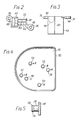
- the connector 32 is conventional except for the provision of two apertured lugs 36 at the top which snap on to pegs 38 depending from a cover plate 40.
- the cover plate has more than two pegs 38 but only two are shown in Figure 1, again to avoid confusing the drawing. It can clearly be seen that the cover plate 40 is supported in a fixed position relative to the pump 14 through the intermediary of the connector 32. The cover plate covers over the recess 12 so that further protection for the pump is provided, in particular for the electrical connections thereto.
- a moulded plastics body 42 houses receptacles 44 for the blade terminals 30 and notches 46 are provided for leading out the wires 34 by way of which the pump 14 is energised.
- the underwise of the cover plate 40 is shown in Figure 4 and the plate is again of moulded plastics material (resistant to fuel, oil, weathering and ageing).
- the plate is shaped to cover the recess 12 ( Figure 1) and has a downturned rim 50 to cooperate snugly with the top of the container 10.
- a representative peg 38 is shown in detail in Figure 5 and has an enlarged head 56 with a chamfer 58 so that a lug 36 can be snapped on to the peg and is then retained securely by the head (although it can be prised off if this is ever needed).
- each pair 38, 52, 54 are spaced in correspondence with the spacing of the connector lug holes 48 ( Figure 2) but are differently positioned to cater for different positions of the blade terminals 30 relative to the open top of the recess 12 to be covered over by the plate 40.
- Three different possibilites are allowed for in this specific embodiment and for each application, depending on the container and pump model selected the appropriate pair of pegs is used.
- the pegs are coded by adjacent embossed letters V, B and H for the pairs 38, 52, 54 respectively and signs - and + further denote which peg is adjacent the negative and which adjacent the positive receptacle of the connector 32.
- the pegs may have a diameter of 2.5 mm with heads 3.3 mm in diameter while the holes 48 have a diameter of 3 mm, -0 mm, +0.2 mm.
- the mouths of the holes 48 are slightly flared.
- the container 10 is elongated in the direction normal to the plane of the drawing in Figure 1 and has two integral flanges at the two ends of that face which is recessed to accommodate the pump, i.e. the right hand face in Figure 1.
- These flanges are used to fix the container against a mounting surface of the vehicle, e.g. by bolts through the flanges and this mounting surface completes the enclosure and protection of the pump and the electrical connections. Therefore the unit can be mounted externally and in one practical application, the mounting surface is the outside of a rear cross beam of a tractor cab below a rear window which the unit serves.
Landscapes
- Engineering & Computer Science (AREA)
- Water Supply & Treatment (AREA)
- Mechanical Engineering (AREA)
- Power Engineering (AREA)
- Structures Of Non-Positive Displacement Pumps (AREA)
- Window Of Vehicle (AREA)
- Seal Device For Vehicle (AREA)
- Details Of Reciprocating Pumps (AREA)
- Cleaning By Liquid Or Steam (AREA)
- Vehicle Cleaning, Maintenance, Repair, Refitting, And Outriggers (AREA)
Claims (5)
Priority Applications (9)
| Application Number | Priority Date | Filing Date | Title |
|---|---|---|---|
| DE8181303009T DE3169029D1 (en) | 1981-07-01 | 1981-07-01 | Windscreen washer unit |
| EP81303009A EP0068054B1 (fr) | 1981-07-01 | 1981-07-01 | Ensemble de lave-glaces |
| DE198181303009T DE68054T1 (de) | 1981-07-01 | 1981-07-01 | Windschutzscheiben-wascheinheit. |
| AT81303009T ATE11895T1 (de) | 1981-07-01 | 1981-07-01 | Windschutzscheiben-wascheinheit. |
| ES512342A ES512342A0 (es) | 1981-07-01 | 1982-05-19 | "un dispositivo de lavado de parabrisas". |
| US06/392,447 US4453895A (en) | 1981-07-01 | 1982-06-28 | Windscreen washer unit |
| CA000406234A CA1195060A (fr) | 1981-07-01 | 1982-06-29 | Dispositif laveur de pare-brise |
| ZA824680A ZA824680B (en) | 1981-07-01 | 1982-06-30 | Connector for windshield washer pump |
| MX193398A MX155655A (es) | 1981-07-01 | 1982-06-30 | Mejoras a una unidad limpiadora de parabrisas para automoviles y camiones |
Applications Claiming Priority (1)
| Application Number | Priority Date | Filing Date | Title |
|---|---|---|---|
| EP81303009A EP0068054B1 (fr) | 1981-07-01 | 1981-07-01 | Ensemble de lave-glaces |
Publications (2)
| Publication Number | Publication Date |
|---|---|
| EP0068054A1 EP0068054A1 (fr) | 1983-01-05 |
| EP0068054B1 true EP0068054B1 (fr) | 1985-02-20 |
Family
ID=8188341
Family Applications (1)
| Application Number | Title | Priority Date | Filing Date |
|---|---|---|---|
| EP81303009A Expired EP0068054B1 (fr) | 1981-07-01 | 1981-07-01 | Ensemble de lave-glaces |
Country Status (8)
| Country | Link |
|---|---|
| US (1) | US4453895A (fr) |
| EP (1) | EP0068054B1 (fr) |
| AT (1) | ATE11895T1 (fr) |
| CA (1) | CA1195060A (fr) |
| DE (2) | DE68054T1 (fr) |
| ES (1) | ES512342A0 (fr) |
| MX (1) | MX155655A (fr) |
| ZA (1) | ZA824680B (fr) |
Families Citing this family (7)
| Publication number | Priority date | Publication date | Assignee | Title |
|---|---|---|---|---|
| IT8520964U1 (it) * | 1985-03-01 | 1986-09-01 | Alfa Romeo Auto Spa | Contenitore per il liquido lavavetri di un autoveicolo |
| DE3709926A1 (de) * | 1987-03-26 | 1988-10-06 | Porsche Ag | Scheibenwaschanlage fuer kraftfahrzeuge |
| IT1223818B (it) * | 1988-09-13 | 1990-09-29 | Fiat Auto Spa | Veicolo perfezionato avente un serbatoio incorporato in un elemento strutturale nella scocca del veicolo medesimo |
| DE4033282A1 (de) * | 1990-10-19 | 1992-04-23 | Swf Auto Electric Gmbh | Behaelter, insbesondere fuer scheibenwaschanlagen von kraftfahrzeugen |
| WO2010108286A1 (fr) | 2009-03-27 | 2010-09-30 | Francine Lacoste | Système d'alimentation de lave-glace et procédé associé |
| US20130000281A1 (en) * | 2011-06-30 | 2013-01-03 | Caterpillar Inc. | Def pump mounted to tank |
| US20150114488A1 (en) * | 2013-10-24 | 2015-04-30 | Continental Automotive Systems, Inc. | Integrated fluid reservoir structure and wheel liner splash shield |
Family Cites Families (9)
| Publication number | Priority date | Publication date | Assignee | Title |
|---|---|---|---|---|
| US2309670A (en) * | 1940-07-15 | 1943-02-02 | Edward J Ruthman | Motor housing |
| DE1121198B (de) * | 1959-02-21 | 1962-01-04 | Mez Nachod Narodni Podnik | Umschaltvorrichtung zur Drehrichtungsukehr ein- bzw. zweiphasiger elektrischer Kleinmotoren |
| US3158293A (en) * | 1961-02-17 | 1964-11-24 | Trico Products Corp | Windshield washer |
| US3316847A (en) * | 1964-10-29 | 1967-05-02 | Delman Co | Windshield washer system |
| FR2269437A1 (en) * | 1974-05-03 | 1975-11-28 | Lamaudiere Paul | Timed pulse jet windscreen washer - has timer in recess of reservoir held by a strap |
| DE7536534U (de) * | 1975-11-18 | 1976-05-26 | Westfaelische Metall Industrie Kg, Hueck & Co, 4780 Lippstadt | Halterungsanordnung fuer eine pumpen- motor-einheit der scheibenwaschanlage eines kraftfahrzeuges |
| GB1586227A (en) * | 1977-09-02 | 1981-03-18 | Shell Electric Mfg | Electrical connector for motor windings |
| ES244882Y (es) * | 1979-07-30 | 1984-02-16 | Transpar Iberica Sa | Bomba electrica para lavaparabrisas |
| DE8030909U1 (de) * | 1980-11-19 | 1982-05-13 | Robert Bosch Gmbh, 7000 Stuttgart | Kreiselpumpe zum foerdern von waschfluessigkeit auf die oberflaeche einer scheibe an einem kraftfahrzeug |
-
1981
- 1981-07-01 EP EP81303009A patent/EP0068054B1/fr not_active Expired
- 1981-07-01 DE DE198181303009T patent/DE68054T1/de active Pending
- 1981-07-01 AT AT81303009T patent/ATE11895T1/de active
- 1981-07-01 DE DE8181303009T patent/DE3169029D1/de not_active Expired
-
1982
- 1982-05-19 ES ES512342A patent/ES512342A0/es active Granted
- 1982-06-28 US US06/392,447 patent/US4453895A/en not_active Expired - Fee Related
- 1982-06-29 CA CA000406234A patent/CA1195060A/fr not_active Expired
- 1982-06-30 MX MX193398A patent/MX155655A/es unknown
- 1982-06-30 ZA ZA824680A patent/ZA824680B/xx unknown
Also Published As
| Publication number | Publication date |
|---|---|
| CA1195060A (fr) | 1985-10-15 |
| ATE11895T1 (de) | 1985-03-15 |
| DE3169029D1 (en) | 1985-03-28 |
| EP0068054A1 (fr) | 1983-01-05 |
| ES8305638A1 (es) | 1983-04-16 |
| ES512342A0 (es) | 1983-04-16 |
| ZA824680B (en) | 1984-02-29 |
| DE68054T1 (de) | 1983-09-15 |
| US4453895A (en) | 1984-06-12 |
| MX155655A (es) | 1988-02-26 |
Similar Documents
| Publication | Publication Date | Title |
|---|---|---|
| US4693949A (en) | Storage battery housing | |
| US5169338A (en) | Battery connector cover | |
| US6919509B2 (en) | Electrical junction box | |
| EP0068054B1 (fr) | Ensemble de lave-glaces | |
| JPH03501319A (ja) | 自動車における風防ワイパ装置を駆動するためのワイパモータ用の電気モータ | |
| US10527464B2 (en) | Rotatable sensor cover | |
| GB2169130A (en) | Electric storage battery | |
| JP2514449Y2 (ja) | ヒュ―ズボックス | |
| US4932875A (en) | Multipolar connector | |
| JP4503840B2 (ja) | 消費部に信号線と電流供給線を接続する差込みコネクタ | |
| JPH0679073U (ja) | 燃料タンク用コネクタ | |
| US6132256A (en) | Design of a lambda module with mating plug | |
| US5564944A (en) | Dripproof connector | |
| JPH01286755A (ja) | 車両用発電機 | |
| JP2594610Y2 (ja) | 電気接続箱 | |
| US6635823B2 (en) | Cover for preventing water from entering a junction block | |
| US4331749A (en) | Storage battery structure | |
| JPH082904Y2 (ja) | リレーターミナル | |
| JP7554032B2 (ja) | カバー部材及びカバー部材を備える電子式電力量計 | |
| JP2508977Y2 (ja) | 端子保護キャップ | |
| CN220358419U (zh) | 防冷凝水连接器结构和电池管理系统连接器 | |
| JP4392145B2 (ja) | アース用防水構造 | |
| JP7444739B2 (ja) | コネクタ | |
| JPS6348945Y2 (fr) | ||
| JPH09178510A (ja) | 電子タコグラフ |
Legal Events
| Date | Code | Title | Description |
|---|---|---|---|
| PUAI | Public reference made under article 153(3) epc to a published international application that has entered the european phase |
Free format text: ORIGINAL CODE: 0009012 |
|
| 17P | Request for examination filed |
Effective date: 19820407 |
|
| AK | Designated contracting states |
Designated state(s): AT DE FR GB IT SE |
|
| ITCL | It: translation for ep claims filed |
Representative=s name: LENZI & C. |
|
| EL | Fr: translation of claims filed | ||
| RBV | Designated contracting states (corrected) |
Designated state(s): AT DE FR GB IT SE |
|
| TCAT | At: translation of patent claims filed | ||
| DET | De: translation of patent claims | ||
| ITF | It: translation for a ep patent filed | ||
| GRAA | (expected) grant |
Free format text: ORIGINAL CODE: 0009210 |
|
| AK | Designated contracting states |
Designated state(s): AT DE FR GB IT SE |
|
| REF | Corresponds to: |
Ref document number: 11895 Country of ref document: AT Date of ref document: 19850315 Kind code of ref document: T |
|
| REF | Corresponds to: |
Ref document number: 3169029 Country of ref document: DE Date of ref document: 19850328 |
|
| ET | Fr: translation filed | ||
| PLBE | No opposition filed within time limit |
Free format text: ORIGINAL CODE: 0009261 |
|
| STAA | Information on the status of an ep patent application or granted ep patent |
Free format text: STATUS: NO OPPOSITION FILED WITHIN TIME LIMIT |
|
| 26N | No opposition filed | ||
| PG25 | Lapsed in a contracting state [announced via postgrant information from national office to epo] |
Ref country code: SE Effective date: 19880702 |
|
| ITTA | It: last paid annual fee | ||
| PGFP | Annual fee paid to national office [announced via postgrant information from national office to epo] |
Ref country code: GB Payment date: 19910617 Year of fee payment: 11 |
|
| PGFP | Annual fee paid to national office [announced via postgrant information from national office to epo] |
Ref country code: FR Payment date: 19910705 Year of fee payment: 11 |
|
| PGFP | Annual fee paid to national office [announced via postgrant information from national office to epo] |
Ref country code: AT Payment date: 19910708 Year of fee payment: 11 |
|
| PG25 | Lapsed in a contracting state [announced via postgrant information from national office to epo] |
Ref country code: GB Effective date: 19920701 Ref country code: AT Effective date: 19920701 |
|
| GBPC | Gb: european patent ceased through non-payment of renewal fee |
Effective date: 19920701 |
|
| PG25 | Lapsed in a contracting state [announced via postgrant information from national office to epo] |
Ref country code: FR Effective date: 19930331 |
|
| REG | Reference to a national code |
Ref country code: FR Ref legal event code: ST |
|
| EUG | Se: european patent has lapsed |
Ref document number: 81303009.5 Effective date: 19890510 |
|
| PGFP | Annual fee paid to national office [announced via postgrant information from national office to epo] |
Ref country code: DE Payment date: 19950817 Year of fee payment: 15 |
|
| PG25 | Lapsed in a contracting state [announced via postgrant information from national office to epo] |
Ref country code: DE Effective date: 19970402 |