EP0068067A1 - Résistance à haute tension pour isolateurs de lignes aériennes - Google Patents
Résistance à haute tension pour isolateurs de lignes aériennes Download PDFInfo
- Publication number
- EP0068067A1 EP0068067A1 EP82100844A EP82100844A EP0068067A1 EP 0068067 A1 EP0068067 A1 EP 0068067A1 EP 82100844 A EP82100844 A EP 82100844A EP 82100844 A EP82100844 A EP 82100844A EP 0068067 A1 EP0068067 A1 EP 0068067A1
- Authority
- EP
- European Patent Office
- Prior art keywords
- voltage
- insulator
- voltage resistor
- resistor
- resistor according
- Prior art date
- Legal status (The legal status is an assumption and is not a legal conclusion. Google has not performed a legal analysis and makes no representation as to the accuracy of the status listed.)
- Granted
Links
- 239000012212 insulator Substances 0.000 claims abstract description 60
- 239000000463 material Substances 0.000 claims description 11
- 239000004033 plastic Substances 0.000 claims description 9
- 229920003023 plastic Polymers 0.000 claims description 9
- 230000002209 hydrophobic effect Effects 0.000 claims description 7
- 239000004020 conductor Substances 0.000 claims description 6
- 239000000919 ceramic Substances 0.000 claims description 5
- 229920002379 silicone rubber Polymers 0.000 claims description 5
- 239000004945 silicone rubber Substances 0.000 claims description 5
- 229920002943 EPDM rubber Polymers 0.000 claims description 4
- 229920001343 polytetrafluoroethylene Polymers 0.000 claims description 4
- 239000004810 polytetrafluoroethylene Substances 0.000 claims description 4
- 239000002131 composite material Substances 0.000 claims description 3
- 239000011521 glass Substances 0.000 claims description 3
- 229920000049 Carbon (fiber) Polymers 0.000 claims description 2
- 239000004917 carbon fiber Substances 0.000 claims description 2
- HQQADJVZYDDRJT-UHFFFAOYSA-N ethene;prop-1-ene Chemical group C=C.CC=C HQQADJVZYDDRJT-UHFFFAOYSA-N 0.000 claims description 2
- VNWKTOKETHGBQD-UHFFFAOYSA-N methane Chemical compound C VNWKTOKETHGBQD-UHFFFAOYSA-N 0.000 claims description 2
- 239000000178 monomer Substances 0.000 claims description 2
- -1 polytetrafluoroethylene Polymers 0.000 claims description 2
- 230000002787 reinforcement Effects 0.000 claims 1
- 238000011109 contamination Methods 0.000 abstract description 5
- 230000001934 delay Effects 0.000 abstract 1
- 230000008021 deposition Effects 0.000 abstract 1
- 239000010410 layer Substances 0.000 description 15
- 238000009413 insulation Methods 0.000 description 11
- 230000015572 biosynthetic process Effects 0.000 description 3
- 239000000835 fiber Substances 0.000 description 3
- 238000001035 drying Methods 0.000 description 2
- 150000003839 salts Chemical class 0.000 description 2
- 230000032683 aging Effects 0.000 description 1
- 230000000712 assembly Effects 0.000 description 1
- 238000000429 assembly Methods 0.000 description 1
- 230000015556 catabolic process Effects 0.000 description 1
- 238000004140 cleaning Methods 0.000 description 1
- 230000000694 effects Effects 0.000 description 1
- 238000010438 heat treatment Methods 0.000 description 1
- 230000001771 impaired effect Effects 0.000 description 1
- 238000002955 isolation Methods 0.000 description 1
- 238000009533 lab test Methods 0.000 description 1
- 239000002184 metal Substances 0.000 description 1
- 229920000642 polymer Polymers 0.000 description 1
- 229910052573 porcelain Inorganic materials 0.000 description 1
- 230000035882 stress Effects 0.000 description 1
- 239000002344 surface layer Substances 0.000 description 1
Images


Classifications
-
- H—ELECTRICITY
- H01—ELECTRIC ELEMENTS
- H01B—CABLES; CONDUCTORS; INSULATORS; SELECTION OF MATERIALS FOR THEIR CONDUCTIVE, INSULATING OR DIELECTRIC PROPERTIES
- H01B17/00—Insulators or insulating bodies characterised by their form
- H01B17/42—Means for obtaining improved distribution of voltage; Protection against arc discharges
Definitions
- the invention relates to a high-voltage resistor to avoid flashovers for outdoor insulation assemblies, consisting of an insulating body and a resistance material, which is connected in series with an insulator.
- a high-voltage resistor to avoid flashovers for outdoor insulation assemblies, consisting of an insulating body and a resistance material, which is connected in series with an insulator.
- one or more high-voltage resistors or high-voltage insulators of any design, such as Long rods, support and cap insulators can be used for both DC and AC voltages.
- the high-voltage resistor is intended to prevent flashovers caused by conductive foreign layers, in particular moistened dirt deposits on the surface of outdoor insulators. With such conductive surfaces, a so-called foreign layer leakage current flows first. With this current, foreign layers are dried out at the points of greatest current density and so-called drying zones are formed. These drying zones are then bridged by partial arcs due to the uneven voltage distribution that arises. If the conductivity of the still wet zones is too high, the partial arcs are extended and there is a flashover in the conductor earth voltage.
- One tries to prevent this flashover by either increasing the creepage distances while maintaining the insulator shape by increasing the overall length or by using insulators with a longer creepage distance while maintaining the overall length.
- a cylindrical resistor in series is assigned to the insulator to avoid flashover. This resistance is dimensioned such that the flowing leakage current over the surface of the insulator remains small and does not exceed a certain value.
- the resistors required for this must have a resistance value in the range of a few megohms to a hundred megohms.
- the disadvantage of this system is that after the formation of a conductive layer on the insulator, almost the entire conductor earth voltage has to be taken over by the resistor, since the value of the surface resistance of the insulator becomes very much lower than that of the resistor connected in series when it is very dirty. Such an insulation arrangement thus becomes very long.
- the arrangement becomes ineffective if a conductive layer forms on the surface of the series resistor due to contamination, so that one is forced, e.g. to install conical covers against pollution, as is apparent from the embodiment of the British patent.
- the object of the present invention is to be seen in specifying a high-voltage resistor for use in a series connection with a high-voltage insulator for outdoor insulation arrangements, in which no flashover occurs on the overall arrangement despite conductive foreign layers and a low overall height can be achieved.
- the object is achieved in that the leakage current pulse characteristic of the high-voltage insulator on the total resistance the high-voltage resistor caused a voltage drop of at least 5, preferably 10-30% of the total conductor earth voltage and its shape is modeled on a shield insulator.
- this high-voltage resistor must be resistant to arcing and breakdown and must be designed so that an electrically parallel conductive layer on its surface changes its total resistance value only slightly.
- this is achieved by means of outer contours with a comparatively high specific creepage distance and, if one wishes to obtain an even shorter overall length of the outdoor insulation arrangement, by forming the outer surface from a hydrophobic material such as polytetrafluoroethylene (PTFE), ethylene propylene monomer (EPM), ethylene propylene diene monomer (EPDM). or silicone rubber reached.
- a hydrophobic material such as polytetrafluoroethylene (PTFE), ethylene propylene monomer (EPM), ethylene propylene diene monomer (EPDM). or silicone rubber reached.
- PTFE polytetrafluoroethylene
- EPM ethylene propylene monomer
- EPDM ethylene propylene diene monomer
- silicone rubber silicone rubber
- the insulating body can consist of ceramic, glass or plastic and the resistance material can be applied to it in the form of spirals or conductive or semiconductive layers.
- a special embodiment of the inventive idea is that the insulating body is hollow.
- Other features regarding the embodiment of the invention go from the subclaims or from the description.
- An advantage of the embodiment of the device according to the invention consists in a small overall length of the entire insulation arrangement, as a result of which an economical and, as a result of the lower mast height of an overhead line, an environmentally friendly design is achieved.
- it proves to be particularly advantageous in the context of the invention that existing insulation arrangements in which the foreign-layer loads have become stronger over time can be prevented from flashover or from constant cleaning by using the high-voltage resistor according to the invention in series built in.
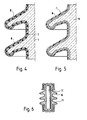
- the device according to the invention of the high-voltage resistor 1, 1a, 1b is shown in series with the actual outdoor insulator 2, 2a, 2b in FIGS. 1 to 3, the outdoor insulator in FIG. 1 as a long bar insulator, in FIG. 2 as a post insulator and in FIG. 3 is shown as a chain of cap insulators.
- a resistor for use with a long bar insulator 2 is shown in section. It consists of a resistance wire 3 which is applied to the surface of an insulating body 4 e.g. a porcelain insulator is applied in a spiral shape and is embedded in a glaze 5. The surface is covered with a hydrophobic layer 6 e.g. made of silicone rubber.
- FIG. 5 Another embodiment is shown in FIG. 5.
- a conductive glaze 7 is applied to the surface of the insulating body 4, on which in turn a hydrophobic layer 6 is applied.
- Wire or film resistors designed in this way can of course not only be used for long-rod insulators, but also for post insulators, a chain of cap insulators or for bushings, since there are no technical difficulties in adapting the shield shape of the resistor to the shape of these insulators.
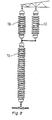
- an insulating body 4 being used which is cylindrical.
- One or more parallel resistance wires 3 are embedded in the glaze on the cylindrical surface, similar to the conventional glazed wire resistors: Shields 8 made of open-air resistant plastic material such as e.g. Silicone rubber applied in the form of insulator shields.
- FIG. 10 differs from FIG. 9 only in that instead of a wire resistor, a sheet resistor 9 is used, which is either formed by a conductive glaze or by a thin metal layer, the resistor being either continuous or spiral.
- a wire resistor instead of a wire resistor, a sheet resistor 9 is used, which is either formed by a conductive glaze or by a thin metal layer, the resistor being either continuous or spiral.
- FIG. 6 A further embodiment of the resistor can also be seen in FIG. 6.
- a cylindrical resistor 10 inside a hollow insulator 11.
- the surface of the hollow insulator can in turn be coated with a hydrophobic material 6.
- High-voltage resistors in the embodiment according to FIG. 6 can be used for outdoor insulation arrangements with long rods Fig. 1 or supports according to Fig. 2 are used, wherein the insulating body 11 must be mechanically sufficiently strong. 6 can also be used advantageously in outdoor insulation arrangements without meeting high mechanical requirements.
- Such an arrangement of the high-voltage resistor 15 for a long-rod insulator 19 is shown in FIG. 8. The insulator 18 only serves to take over the mechanical forces of the actual insulator 19; it is bridged electrically by the resistor 15 connected in parallel.
- the effectiveness of the cylindrical resistor 10 according to FIG. 6 must not be significantly impaired by the additional electrical parallel connection of the surface of the uppermost long rod insulator 18, which is conductive due to contamination, to the outer surface of the resistor 15, which is conductive due to contamination.
- This requirement can usually be met with a suitable design of the shields and the surfaces of the long rod insulator 18 of the resistor 15 and the inventive dimensioning of the cylindrical resistor 10;
- a resistance value of the cylindrical resistor 10 of 20 kOhm can apply and a resistance value for the surface of the uppermost long rod 18, as well as the resistor 15, which is conductive due to heavy contamination about 100 kOhm.
- the insulating body 11 is also designed as a hollow insulator.
- the resistor 12 is formed in one of the embodiments of FIG. 4 or 5.
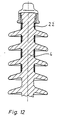
- Another embodiment is to integrate the high voltage resistor, as shown in FIG. 11, into the isolator of the outdoor isolation arrangement.
- the resistance can be implemented in the embodiment according to FIG. 4, as shown in FIG. 11, or according to FIG. 5.
- the resistor is again integrated into the insulator of the outdoor arrangement, but, in contrast to FIG. 11, is arranged distributed.
- the distributed partial resistors 22 can again be constructed as shown in FIG. 4 or 5, as shown in FIG. 11.
- the resistor is constructed on the principle of a plastic composite insulator, with a fiber reinforced core 13 with conductive fibers, e.g. Carbon fiber is used, over which a shield cover 14, e.g. made of silicone rubber.
- a ceramic long rod L 75/22 with a length of 1270 mm and a creepage distance of 2440 mm was used as the insulator, in accordance with the regulations of DIN 48006/2.
- a standing salt content of 28 kg / m 3 at 63 kV was achieved with the resistor according to the invention for the conventional arrangement, that is to say without series connection.
- the critical leakage current pulse at the flashover was measured at 1072 mA (peak value). This leakage current pulse is characteristic of the isolator used. The tests were carried out with a rigid voltage source (short-circuit current 20 A).
- an inventive resistor according to FIG. 6 with an overall length of 160 mm was additionally used, which had a resistance value of 13 kOhm and was connected in series with the insulator L75 / 22.
- the insulator could not even with the highest possible salinity (224 kg / m 3 ) more to roll over.
- the highest leakage current pulse was 2110 mA.
- the comparatively tested arrangement consisted of the isolator chain, to which an inventive high-voltage resistor of 13 kOhm was connected in series. Salinity, 224 kg / m l in the same test voltage of 60.6 kV, the cap chain could not be brought to flashover. In the test without flashover, the highest leakage current pulse was 5515 mA.
Landscapes
- Engineering & Computer Science (AREA)
- Power Engineering (AREA)
- Insulators (AREA)
Priority Applications (2)
| Application Number | Priority Date | Filing Date | Title |
|---|---|---|---|
| AT82100844T ATE16431T1 (de) | 1981-06-26 | 1982-02-05 | Hochspannungswiderstand fuer freiluftisolieranordnungen. |
| NO821615A NO161704C (no) | 1981-06-26 | 1982-05-14 | Hoeyspenningsmotstand og anvendelse av denne i friluftshoeyspennings-isolatorer. |
Applications Claiming Priority (2)
| Application Number | Priority Date | Filing Date | Title |
|---|---|---|---|
| DE3125203 | 1981-06-26 | ||
| DE3125203 | 1981-06-26 |
Publications (2)
| Publication Number | Publication Date |
|---|---|
| EP0068067A1 true EP0068067A1 (fr) | 1983-01-05 |
| EP0068067B1 EP0068067B1 (fr) | 1985-11-06 |
Family
ID=6135469
Family Applications (1)
| Application Number | Title | Priority Date | Filing Date |
|---|---|---|---|
| EP82100844A Expired EP0068067B1 (fr) | 1981-06-26 | 1982-02-05 | Résistance à haute tension pour isolateurs de lignes aériennes |
Country Status (6)
| Country | Link |
|---|---|
| US (1) | US4524404A (fr) |
| EP (1) | EP0068067B1 (fr) |
| JP (1) | JPS585911A (fr) |
| CA (1) | CA1198489A (fr) |
| DE (1) | DE3267216D1 (fr) |
| ZA (1) | ZA823948B (fr) |
Cited By (1)
| Publication number | Priority date | Publication date | Assignee | Title |
|---|---|---|---|---|
| CN109448942A (zh) * | 2018-12-13 | 2019-03-08 | 合肥金瑞配网电气设备有限公司 | 一种带电压监测接口的避雷器 |
Families Citing this family (13)
| Publication number | Priority date | Publication date | Assignee | Title |
|---|---|---|---|---|
| US4835341A (en) * | 1988-03-08 | 1989-05-30 | Maxwell Laboratories, Inc. | Electrical insulator for use in plasma environment |
| CN1089477C (zh) * | 1994-03-28 | 2002-08-21 | 日本碍子株式会社 | 具有导电表面涂层以防止电晕放电的绝缘子 |
| JP2004213984A (ja) * | 2002-12-27 | 2004-07-29 | Ngk Insulators Ltd | ポリマーポスト碍子装置及びその装着方法 |
| EP1748449A1 (fr) * | 2005-07-25 | 2007-01-31 | Siemens Aktiengesellschaft | Isolateur avec une capacité augmentée d'isolation |
| DE102006004811A1 (de) * | 2006-01-26 | 2007-08-09 | Siemens Ag | Elektrisches Schaltgerät mit Potentialsteuerung |
| US8426736B2 (en) * | 2009-07-17 | 2013-04-23 | The Invention Science Fund I Llc | Maintaining insulators in power transmission systems |
| US8692537B2 (en) * | 2009-07-17 | 2014-04-08 | The Invention Science Fund I, Llc | Use pairs of transformers to increase transmission line voltage |
| US20110011621A1 (en) * | 2009-07-17 | 2011-01-20 | Searete Llc, A Limited Liability Corporation Of The State Of Delaware | Smart link coupled to power line |
| KR20110068420A (ko) * | 2009-12-16 | 2011-06-22 | (주)디티알 | 폴리머 핀 애자 및 폴리머 핀 애자의 제조 방법 |
| US8704097B2 (en) | 2012-01-23 | 2014-04-22 | General Electric Company | High voltage bushing assembly |
| US8716601B2 (en) | 2012-02-08 | 2014-05-06 | General Electric Company | Corona resistant high voltage bushing assembly |
| JP5586808B1 (ja) * | 2013-09-06 | 2014-09-10 | 三菱電機株式会社 | 電力用開閉装置用の絶縁支持体 |
| CN104992793B (zh) * | 2015-07-08 | 2017-03-01 | 清华大学深圳研究生院 | 防覆冰绝缘子设备及输电线路 |
Citations (3)
| Publication number | Priority date | Publication date | Assignee | Title |
|---|---|---|---|---|
| AT175926B (de) * | 1951-03-13 | 1953-08-25 | Bbc Brown Boveri & Cie | Aus Gliedisolatoren aufgebauter ein- oder mehrbeiniger Stützisolator in Höchstspannungsanlagen |
| GB1039193A (en) * | 1964-05-22 | 1966-08-17 | Midland Silicones Ltd | Improvements in or relating to electrical insulators |
| GB1296038A (fr) * | 1969-01-14 | 1972-11-15 |
Family Cites Families (13)
| Publication number | Priority date | Publication date | Assignee | Title |
|---|---|---|---|---|
| US1449694A (en) * | 1919-09-18 | 1923-03-27 | Gen Electric | Protective device |
| FR528337A (fr) * | 1920-12-03 | 1921-11-10 | Ignazio Prinetti | Dispositif destiné à signaler l'isolement diminué ou insuffisant d'un isolateur dans les lignes de transmission |
| GB527357A (en) * | 1939-03-27 | 1940-10-08 | Charles William Marshall | Improvements relating to high voltage insulators |
| CH288561A (de) * | 1951-03-13 | 1953-01-31 | Bbc Brown Boveri & Cie | Aus Gliedisolatoren aufgebauter ein- oder mehrbeiniger Stützisolator in Höchstspannungsanlagen. |
| DE969089C (de) * | 1951-08-07 | 1958-04-30 | Hans Von Cron Dipl Ing | Selbstreinigender Freilufthochspannungsisolator |
| US2776332A (en) * | 1952-06-25 | 1957-01-01 | Siemens Ag | Self-cleaning outdoor high-tension insulators |
| GB869797A (en) * | 1958-07-11 | 1961-06-07 | Henry Herbert Goldstaub | Improvements in or relating to high-tension electrical insulators |
| GB940400A (en) * | 1961-06-06 | 1963-10-30 | Central Electr Generat Board | Improvements in or relating to electrical insulators |
| GB1014624A (en) * | 1963-12-12 | 1965-12-31 | Central Electr Generat Board | Improvements in or relating to electrical insulators |
| DE2006247A1 (de) * | 1970-02-12 | 1971-10-07 | Jenaer Glaswerk Schott & Gen | Hochspannungsisolator |
| DE2034463A1 (de) * | 1970-07-11 | 1972-01-20 | Siemens Ag | Isolatoren, insbesondere mehrteilige Isolatoren mit großen Einzelisolierstrecken |
| DE2361204C3 (de) * | 1973-12-06 | 1978-11-23 | Siemens Ag, 1000 Berlin Und 8000 Muenchen | Elektrische Hochspannungseinrichtung mit Isolierkörpern |
| FR2412150A1 (fr) * | 1977-12-14 | 1979-07-13 | Ceraver | Isolateur electrique de ligne en matiere organique |
-
1982
- 1982-02-05 EP EP82100844A patent/EP0068067B1/fr not_active Expired
- 1982-02-05 DE DE8282100844T patent/DE3267216D1/de not_active Expired
- 1982-06-03 US US06/384,603 patent/US4524404A/en not_active Expired - Fee Related
- 1982-06-04 ZA ZA823948A patent/ZA823948B/xx unknown
- 1982-06-25 CA CA000405983A patent/CA1198489A/fr not_active Expired
- 1982-06-25 JP JP57108591A patent/JPS585911A/ja active Granted
Patent Citations (3)
| Publication number | Priority date | Publication date | Assignee | Title |
|---|---|---|---|---|
| AT175926B (de) * | 1951-03-13 | 1953-08-25 | Bbc Brown Boveri & Cie | Aus Gliedisolatoren aufgebauter ein- oder mehrbeiniger Stützisolator in Höchstspannungsanlagen |
| GB1039193A (en) * | 1964-05-22 | 1966-08-17 | Midland Silicones Ltd | Improvements in or relating to electrical insulators |
| GB1296038A (fr) * | 1969-01-14 | 1972-11-15 |
Cited By (2)
| Publication number | Priority date | Publication date | Assignee | Title |
|---|---|---|---|---|
| CN109448942A (zh) * | 2018-12-13 | 2019-03-08 | 合肥金瑞配网电气设备有限公司 | 一种带电压监测接口的避雷器 |
| CN109448942B (zh) * | 2018-12-13 | 2024-03-12 | 合肥金瑞配网电气设备有限公司 | 一种带电压监测接口的避雷器 |
Also Published As
| Publication number | Publication date |
|---|---|
| JPS6359208B2 (fr) | 1988-11-18 |
| CA1198489A (fr) | 1985-12-24 |
| US4524404A (en) | 1985-06-18 |
| DE3267216D1 (en) | 1985-12-12 |
| JPS585911A (ja) | 1983-01-13 |
| EP0068067B1 (fr) | 1985-11-06 |
| ZA823948B (en) | 1983-07-27 |
Similar Documents
| Publication | Publication Date | Title |
|---|---|---|
| EP0774157B1 (fr) | Isolateur electrique en caoutchouc de silicone pour applications haute tension | |
| EP0068067B1 (fr) | Résistance à haute tension pour isolateurs de lignes aériennes | |
| EP2243145B1 (fr) | Isolateur composite à commande de champ | |
| DE102012204052B4 (de) | Hochspannungsdurchführung mit leitenden Einlagen für Gleichspannung und Verfahren zu ihrer Herstellung | |
| DE2501811A1 (de) | Hochspannungskabel mit synthetischer isolation und halbleitender beschichtung | |
| EP3639282B1 (fr) | Conduite haute tension enfichable et appareil électrique comportant une conduite haute tension enfichable | |
| DE2037921A1 (de) | Blitzschutzeinnchtung | |
| DE2933820C2 (de) | Vakuumschalter | |
| DE3779835T2 (de) | Keramischer isolator. | |
| EP1921724B1 (fr) | Dispositif de maintien à distance destiné à garantir l'intervalle de séparation entre des installations de paratonnerre partiellement isolées | |
| DE296565C (fr) | ||
| DE1690802A1 (de) | Anordnung zum Schirmen oder Rippen an elektrischen Isolierkoerpern | |
| DE102009056291B4 (de) | Isolierte Blitzschutzanlage | |
| DE69209325T2 (de) | Anschlussklemme für Hochspannung | |
| DE2710019A1 (de) | Elektrischer schirmisolator | |
| DE714920C (de) | UEberspannungsableiter | |
| DE3306307C2 (de) | Zylindrischer Stützisolator | |
| DE450456C (de) | Hochspannungsapparat, insbesondere mit OElisolierung | |
| DE913660C (de) | Freileitungsanlage, deren Isolatoren wegen Verschmutzungsgefahr ueberdimensioniert sind | |
| DE874039C (de) | Isolationsanordnung fuer hohe Gleichspannungen | |
| CH718512B1 (de) | Stütz-Halterung für Vogelschutz-Drähte. | |
| DE1538405A1 (de) | UEberspannungsableiter | |
| DE1088568B (de) | Stabfoermiger Hochspannungsisolator mit Stellen verschiedener Leitfaehigkeit, vorzugsweise aus Giessharz | |
| DE1045502B (de) | Elektrischer Freiluft-Stabisolator | |
| CH170845A (de) | Verfahren für die Herstellung von Erzeugnissen mit gegeneinander isolierten elektrischen Leitern und nach diesem Verfahren hergestellter isolierter Leiter. |
Legal Events
| Date | Code | Title | Description |
|---|---|---|---|
| PUAI | Public reference made under article 153(3) epc to a published international application that has entered the european phase |
Free format text: ORIGINAL CODE: 0009012 |
|
| AK | Designated contracting states |
Designated state(s): AT BE CH DE FR GB IT LI LU NL SE |
|
| 17P | Request for examination filed |
Effective date: 19830614 |
|
| GRAA | (expected) grant |
Free format text: ORIGINAL CODE: 0009210 |
|
| AK | Designated contracting states |
Designated state(s): AT BE CH DE FR GB IT LI LU NL SE |
|
| REF | Corresponds to: |
Ref document number: 16431 Country of ref document: AT Date of ref document: 19851115 Kind code of ref document: T |
|
| REF | Corresponds to: |
Ref document number: 3267216 Country of ref document: DE Date of ref document: 19851212 |
|
| ITF | It: translation for a ep patent filed | ||
| ET | Fr: translation filed | ||
| PG25 | Lapsed in a contracting state [announced via postgrant information from national office to epo] |
Ref country code: LU Free format text: LAPSE BECAUSE OF NON-PAYMENT OF DUE FEES Effective date: 19860228 |
|
| PLBE | No opposition filed within time limit |
Free format text: ORIGINAL CODE: 0009261 |
|
| STAA | Information on the status of an ep patent application or granted ep patent |
Free format text: STATUS: NO OPPOSITION FILED WITHIN TIME LIMIT |
|
| 26N | No opposition filed | ||
| PGFP | Annual fee paid to national office [announced via postgrant information from national office to epo] |
Ref country code: SE Payment date: 19890119 Year of fee payment: 8 |
|
| PGFP | Annual fee paid to national office [announced via postgrant information from national office to epo] |
Ref country code: AT Payment date: 19890124 Year of fee payment: 8 |
|
| PGFP | Annual fee paid to national office [announced via postgrant information from national office to epo] |
Ref country code: NL Payment date: 19890228 Year of fee payment: 8 |
|
| PGFP | Annual fee paid to national office [announced via postgrant information from national office to epo] |
Ref country code: GB Payment date: 19890331 Year of fee payment: 8 |
|
| PGFP | Annual fee paid to national office [announced via postgrant information from national office to epo] |
Ref country code: DE Payment date: 19890413 Year of fee payment: 8 |
|
| PGFP | Annual fee paid to national office [announced via postgrant information from national office to epo] |
Ref country code: FR Payment date: 19900125 Year of fee payment: 9 |
|
| PG25 | Lapsed in a contracting state [announced via postgrant information from national office to epo] |
Ref country code: GB Effective date: 19900205 Ref country code: AT Effective date: 19900205 |
|
| PG25 | Lapsed in a contracting state [announced via postgrant information from national office to epo] |
Ref country code: SE Effective date: 19900206 |
|
| PGFP | Annual fee paid to national office [announced via postgrant information from national office to epo] |
Ref country code: LU Payment date: 19900228 Year of fee payment: 9 |
|
| PGFP | Annual fee paid to national office [announced via postgrant information from national office to epo] |
Ref country code: BE Payment date: 19900405 Year of fee payment: 9 |
|
| PGFP | Annual fee paid to national office [announced via postgrant information from national office to epo] |
Ref country code: CH Payment date: 19900423 Year of fee payment: 9 |
|
| PG25 | Lapsed in a contracting state [announced via postgrant information from national office to epo] |
Ref country code: NL Effective date: 19900901 |
|
| GBPC | Gb: european patent ceased through non-payment of renewal fee | ||
| NLV4 | Nl: lapsed or anulled due to non-payment of the annual fee | ||
| PG25 | Lapsed in a contracting state [announced via postgrant information from national office to epo] |
Ref country code: DE Effective date: 19901201 |
|
| PG25 | Lapsed in a contracting state [announced via postgrant information from national office to epo] |
Ref country code: LI Effective date: 19910228 Ref country code: CH Effective date: 19910228 Ref country code: BE Effective date: 19910228 |
|
| PG25 | Lapsed in a contracting state [announced via postgrant information from national office to epo] |
Ref country code: FR Effective date: 19911031 |
|
| REG | Reference to a national code |
Ref country code: CH Ref legal event code: PL |
|
| REG | Reference to a national code |
Ref country code: FR Ref legal event code: ST |
|
| EUG | Se: european patent has lapsed |
Ref document number: 82100844.8 Effective date: 19901107 |